Volume 2010, Article ID 805216,16pages doi:10.1155/2010/805216
Research Article
Analysis and Construction of Full-Diversity Joint Network-LDPC
Codes for Cooperative Communications
Dieter Duyck,
1Daniele Capirone,
2Joseph J. Boutros,
3and Marc Moeneclaey
11Department of Telecommunications and Information Processing, Ghent University, St-Pietersnieuwstraat 41, B-9000 Gent, Belgium 2Department of Electronics, Politecnico di Torino, Corso Duca Degli Abruzzi 24, 10129 Torino, Italy
3Electrical Engineering Department, Texas A&M University at Qatar, 23874 Doha, Qatar
Correspondence should be addressed to Dieter Duyck,[email protected]
Received 29 December 2009; Revised 14 April 2010; Accepted 3 June 2010 Academic Editor: Christoph Hausl
Copyright © 2010 Dieter Duyck et al. This is an open access article distributed under the Creative Commons Attribution License, which permits unrestricted use, distribution, and reproduction in any medium, provided the original work is properly cited. Transmit diversity is necessary in harsh environments to reduce the required transmit power for achieving a given error performance at a certain transmission rate. In networks, cooperative communication is a well-known technique to yield transmit diversity and network coding can increase the spectral efficiency. These two techniques can be combined to achieve a double diversity order for a maximum coding rateRc =2/3 on the Multiple-Access Relay Channel (MARC), where two sources share
a common relay in their transmission to the destination. However, codes have to be carefully designed to obtain the intrinsic diversity offered by the MARC. This paper presents the principles to design a family of full-diversity LDPC codes with maximum rate. Simulation of the word error rate performance of the new proposed family of LDPC codes for the MARC confirms the full diversity.
1. Introduction
Multipath propagation (small-scale fading) is an important salient effect of wireless channels, causing possible destruc-tive adding of signals at the receiver. When the fading varies very slowly, error-correcting codes cannot combat the detrimental effect of the fading on a point-to-point channel. Space diversity, that is, transmitting information over independent paths in space, is a means to mitigate the effects of slowly varying fading. Cooperative communication [1–4] is a well-known technique to yield transmit diversity. The most elementary example of a cooperative network is the relay channel, consisting of a source, a relay, and a destination [3,5]. The task of the relay is specified by the strategy or protocol. In the case of coded cooperation [4], the relay decodes the message received from the source, and then transmits to the destination additional parity bits related to the message; this results in a higher information theoretic spectral efficiency than simply repeating the message received from the source [6]. The resulting outage probability [7] exhibits twice the diversity, as compared to point-to-point transmission. However, the overall error-correcting code
should be carefully designed in order to guarantee full diversity [8].
We focus on capacity achieving codes, more precisely, low-density parity-check (LDPC) codes [9], because their word error rate (WER) performance is quasi-independent of the block length [10] when the block length is becoming very large.
Considering two users, S1 and S2, and a common destinationD, a double diversity order can be obtained by cooperating. When nocommonrelayRis used, the maximum achievable coding rate that allows to achieve full diversity is Rc = 0.5 (according to the blockwise Singleton bound
[7,11]). However, when one common relayRfor two users is used (a Multiple Access Relay Channel—MARC), it can be proven that the maximum achievable coding rate yielding full diversity isRc=2/3 [12]. The increase of the maximum
coding rate yielding full diversity from Rc = 0.5 to Rc =
a linear block code. Hence, the destination will decode a joint network-channel code. Therefore, the problem formulation is how to design a full-diversity joint network-channel code construction for a rateRc=2/3.
Up till now, no family of full-diversity LDPC codes with Rc = 2/3 for coded cooperation on the MARC has been
published. Chebli, Hausl, and Dupraz obtained interesting results on joint network-channel coding for the MARC with turbo codes [14] and LDPC codes [15,16], but these authors do not elaborate on a structure to guarantee full diversity at maximum rate, which is the most important criterion for a good performance on fading channels. A full-diversity code structure describes a family of LDPC codes or an ensemble of LDPC codes, permitting to generate many specific instances of LDPC codes.
In this paper, we present a strategy to produce excel-lent LDPC codes for the MARC. First, we outline the physical layer network coding framework. Then, we derive the conditions on the MARC model and the coding rate necessary to achieve a double diversity order. In the second part of the paper, we elaborate on the code construction. A joint network-channel code construction is derived that guarantees full diversity, irrespective of the parameters of the LDPC code (the degree distributions). Finally, the coding gain can be improved by selecting the appropriate degree distributions of the LDPC code [17] or using the doping
technique [18] as shown in Section 7.2. Simulation results for finite and infinite length (through density evolution) are provided. To the best of authors’ knowledge, this is the first time that a joint full-diversity network-channel LDPC code construction for maximum rate is proposed.
Channel-State Information is assumed to be available only at the decoder. In order to simplify the analysis, we consider orthogonal half-duplex devices that transmit in separate timeslots.
2. System Model and Notation
2.1. Multiple Access Relay Channel. We consider a Multiple Access Relay Channel (MARC) with two users S1 and S2, a common relay R, and a common destination D. Each of the three transmitting devices transmits in a different timeslot:S1in timeslot 1,S2in timeslot 2, andRin timeslot
3 (Figure 1). In this paper, we limit the scheme to two
sources, but any extension to a larger number of sources is possible by applying the principles explained in the paper. We consider a joint network-channel code over this network, that is, anoverallcodewordc = [c1,. . .,cN]T is received at
the destination during timeslot 1, timeslot 2, and timeslot 3, which form together one coding block. The codeword is partitioned into three parts: cT = [c(1)T
c(2)Tc(3)T], where c(1) = [c1,. . .,cNs]
T
, c(2) = [cNs+1,. . .,c2Ns] T
, and c(3)=[c2Ns+1,. . .,cN]
T
, and whereS1andS2transmitNsbits
(note that each user is given an equal slot length because of fairness), andRtransmitsNrbits, so thatN=2Ns+Nr. We
define the level of cooperation,β, as the ratioNr/N. Because
the users do not communicate between each other, the bits
S1
S2
R
D Timeslot 1
Timeslot 3
Timeslot 2
Figure1: The multiple access relay channel model. The solid arrows correspond to timeslot 1, the dotted arrows to timeslot 2, and the dashed arrow to timeslot 3.
c(1), transmitted byS1, and the bitsc(2), transmitted byS2, are independent.
Since the focus in this paper is on coding, BPSK signaling is used for simplicity, so that the transmitters send symbols x(b)n ∈ {±1}, where b stands for the timeslot number
andnis the symbol time index in timeslotb. The channel is memoryless with real additive white Gaussian noise and multiplicative real fading. The fading coefficients are only known at the decoder side where the received signal vector at the destinationDis
y(b)=αbx(b) +w(b), b=1,. . ., 3, (1)
where y(1) = [y(1)1,. . .,y(1)Ns] T
, y(2) = [y(2)1,. . ., y(2)Ns]
T, andy(3) = [y(3)
1,. . .,y(3)Nr]
T are the received
complex signal vectors in timeslots 1, 2, and 3, respectively. The noise vectorw(b) consists of independent noise samples which are real Gaussian distributed, that is, w(b)n ∼
N(0,σ2), where 1/2σ2 is the average signal-to-noise ratio γ = Es/N0. The Rayleigh distributed fading coefficientsα1,
α2andα3are independent and identically distributed. (The average signal-to-noise ratios on the S1-D,S2-D; andR-D channels are the same.) The channel model is illustrated in
Figure 2. In some parts of the paper, a block binary erasure
channel (block BEC) [19, 20] will be assumed, which is a special case of block fading. In a block BEC, the fading gains belong to the set {0,∞}, whereα = 0 means the link is a complete erasure, whileα= ∞means the link is perfect.
We assume that no errors occur on theS1-RandS2-R channels. This simplifies the analysis and does not change the criteria for the code to attain full-diversity, as will be shown
inSection 3.2.
2.2. LDPC Coding. We focus on binary LDPC codes C[N, 2K]2 with block length N and dimension 2K, and coding rateRc=2K/N. (We consider two sources each with
c1 c2 · · ·
α1 α2 α3
cNs cNs+1 cNs+2 · · ·
N
c2Ns c2Ns+1 c2Ns+2 · · · cN
Figure2: Codeword representation for a multiple access relay channel. The fading gainsα1,α2, andα3are independent.
dbones in each column anddcones in each row. For irregular
(λ(x),ρ(x)) LDPC codes, these numbers are replaced by the so-called degree distributions [9]. These distributions are the standard polynomialsλ(x) andρ(x) [21]:
λ(x)= db
i=2
λixi−1, ρ(x)= dc
i=2
ρixi−1, (2)
whereλi(resp.,ρi) is the fraction of all edges in the Tanner
graph, connected to a bit node (resp., check node) of degree i. Therefore,λ(x) andρ(x) are sometimes referred to as left and right degree distributions from an edge perspective. In
Section 6, the polynomialsλ(x) and◦ ρ(x), which are the left◦
and right distributions from a node perspective, will also be adopted:
◦
λ(x)= db
i=2
◦
λixi−1, ◦
ρ(x)= dc
i=2
◦
ρixi−1, (3)
where λ◦i (resp., ◦
ρi) is the fraction of all bit nodes (resp., check nodes) in the Tanner graph of degree i, henceλ◦i =
(λi/i)/(
jλj/ j) and likewise with ◦
ρi.
The goal of this research is to design a full-diversity ensemble of LDPC codes for the MARC. An ensemble of LDPC codes is the set of all LDPC codes that satisfy the left degree distributionλ(x) and right degree distributionρ(x).
In this paper, not all bit nodes and check nodes in the Tanner graph will be treated equally. To elucidate the different classes of bit nodes and check nodes, a compact representation of the Tanner graph, adopted from [22] and also known as protograph representation [9, 23, 24] (and the references therein), will be used. In this compact Tanner graph, bit nodes and check nodes of the same class are merged into one node.
2.3. Physical Layer Network Coding. The coded bits transmit-ted byRare a linear transformation of the information bits fromS1andS2, denoted asi(1) andi(2), where both vectors are of lengthK. (In some papers, the coded bits transmitted byRare a linear transformation of the transmitted bits from S1andS2, which boils down to the same as the information bits, since the transmitted bits (parity bits and information bits) are a linear transformation of the information bits.) Let
∗stand for a matrix multiplication in GF(5);
c(3)=T∗
i(1) i(2)
. (4)
The matrixT represents thenetwork code, which has to be designed. Let us splitTinto two matricesHN andVsuch
thatT =H−1
N ∗V, whereHN is anNr×Nrmatrix andVis
anNr×2Kmatrix. Now we have the following relation:
HN∗c(3)=V∗
i(1) i(2)
. (5)
Equation (5) can be inserted into the parity-check matrix defining theoverallerror-correcting code. Instead of design-ingT, we can designHNandVusing principles from coding
theory.
3. Diversity and Outage Probability of MARC
3.1. Achievable Diversity Order. The formal definition of diversity order on a block fading channel is well known [25].
Definition 1. The diversity order attained by a code C is defined as
d= −lim
γ→ ∞
logPe
logγ , (6)
wherePeis the word error rate after decoding.
However, in this document, as far as the diversity order is concerned, we mostly use a block BEC. It has been proved that a coding scheme is of full diversity on the block fading channel if and only if it is of full diversity on a block BEC [22]. The channel model is the same as for block fading, except that the fading gains belong to the set{0,∞}. Suppose that on theS1-D,S2-D, andR-Dlinks, the probability of a complete erasure, that is,α=0, is.
Definition 2. A codeCachieves a diversity orderdon a block BEC if and only if [26]
Pe∝d, (7)
wherePeis the word error rate after decoding and∝means
proportional to.
A diversity order of two is achieved if the destination is capable of retrieving the information bits from S1 and S2, when exactly one of theS1-D,S2-D, orR-Dchannels is erased. The maximum coding rate allowing the destination to do so will be derived inSection 3.4.
3.2. Perfect Source-Relay Channels. Here, we will show that the achieved diversity atDdoes not depend on the quality of the source-relay (S-R) channel. Therefore, in the remainder of the paper, we will assume errorless S-R channels to simplify the analysis.
Let us consider a simple block fading relay channel with one sourceS, one relayR, and one destinationD. All considered point-to-point channels (S-R,S-D,R-D) have an intrinsic diversity order of one. In a cooperative protocol, whereRhas to decode the transmission fromSin the first slot, two cases can be distinguished: (1)Ris able to decode the transmission fromSand cooperates withSin the second slot, hence D receives two messages carrying information fromS; (2) Ris not able to decode the transmission from Sand therefore does not transmit in the second slot, hence D receives only one message carrying information from S, namely, on the S-D channel. Now, the decoding error probability, that is, the WER Pe, at D can be written as
follows:
Pe=P(case 1)P(e|case 1) +P(case 2)P(e|case 2).
(8)
The probability P(case 2) is equal to the probability of erroneous decoding atR. For largeγ, we haveP(case 2) ∝
1/γ andP(case 1) = (1−c/γ) [25], wherecis a constant. The probabilityP(e | case 2) is equal to the probability of erroneous decoding on theS-Dchannel; hence for largeγ, P(e|case 2)∝1/γ. Now, the error probabilityPeat largeγ
is proportional to
Pe∝P(e|case 1) + c
γ2, (9)
where c is a positive constant. According to Definition 1, full-diversity requires that at large γ,Pe ∝ 1/γ2. We see
that this only depends on the behavior of P(e | case 1) at large γ, because the second case where the relay cannot decode the transmission from the source in the first slot does automatically give rise to a double diversity order without the need for any code structure. This means that as far as the diversity order is concerned, it is sufficient to assume errorless S-R channels (yielding Pe = P(e |
case 1)). Furthermore, techniques [8] are known to extend the proposed code construction to nonperfect source-relay channels, so that, for the clarity of the presentation, perfect source-relay channels are assumed in the remainder of the paper.
3.3. Outage Probability of the MARC. We denote an outage event of the MARC byEo. An outage event is the event that
the destination cannot retrieve the information fromS1 or S2, that is, the transmitted rate is larger than or equal to the
instantaneous mutual information. The transmitted rateru
is the averagespectral efficiency of user uwhereasr is the overall spectral efficiency, so thatr =r1+r2. (The average spectral efficiency denotes the average number of bits per overall channel uses, including the channel uses of the other devices, that is, transmitted over the MARC channel.) We can interpreteras the total spectral efficiency, that is, transmitted over the network. The MARC block fading channel has a Shannon capacity, that is, essentially zero since the fading gains make the mutual information a random variable which does not allow to achieve an arbitrarily small word error probability under a certain spectral efficiency. This word error probability is calledinformation outage probabilityin the limit of large block length, denoted by
Pout=P(Eo). (10)
The outage probability is a lower bound on the average word error rate of coded systems [27].
The mutual information from user 1 to the destination is the weighted sum of the mutual informations from the channels from S1-D and R-D. (The transmission of R corresponds to redundancy forS1andS2at the same time. From the point of view ofS1, the transmission ofRcontains interference fromS2. By using the observations fromS2, the decoder at the destination can at most cancel the interference from S2 in the transmission from R.) Hence the spectral efficiencyr1is upper bounded as
r1<
1−β 2
I(S1;D) +βI(R;D), (11)
where (1−β)/2 andβare the fractions of the time during whichS1andRare active [25, Section 5.4.4]. The same holds for user 2:
r2<
1−β 2
I(S2;D) +βI(R;D). (12)
Combining (11) and (12) yields
r <
1−β 2
I(S2;D) +
1−β 2
I(S1;D) + 2βI(R;D).
(13)
However, there is a tighter bound for r. Indeed, (11) and (12) both rely on the fact that the destination can cancel the interference from the other user on the relay-to-destination channel, but therefore, the destination must be able to decode one of the users’ information from their respective transmission. Hence, there exist two scenarios: (1) in the first scenario, D decodes the information of S2 from the transmission ofS2(r2 <((1−β)/2)I(S2;D)), so that it can cancel the interference fromS2 in the transmission fromR ((11) holds); (2) the second scenario is the symmetric case (r1<((1−β)/2)I(S1;D) and (12) holds). Both scenarios lead to a tighter bound forr:
r <
1−β 2
I(S2;D) +
1−β 2
I(S1;D) +βI(R;D).
S1
Figure3: In these three cases, where each time one link is erased, a full-diversity code construction allows the destination to retrieve the information bits from bothS1andS2.
Bound (14) can be verified when considering the instan-taneous mutual information between the sources and the sinks in the network. We denote the instantaneous mutual information of the MARC asI(α,γ), which is a function of the set of fading gainsα = [α1,α2,α3] and average SNRγ. The overall mutual information is
Iα,γ =
because the three timeslots behave as parallel Gaussian chan-nels whose mutual informations add together. Of course, the timeslots timeshare a time-interval, which gives a weight to each mutual information term [25, Section 5.4.4]. The total transmitted rate must be smaller thanI(α,γ), which yields (14).
From the above analysis, we can now write the expression of an outage event:
Eo= average mutual information of a point-to-point channel with inputx ∈ {−1, 1}, received signal y = αx+w withw ∼ N(0,σ2), conditioned on the channel realizationα, which is determined by the following well-known formula [28]:
I(X;Y|α)=1−EY|{x=1,α}
Now, the outage probability can be easily determined through Monte-Carlo simulations to average over the fading gains and to average over the noise. (Averaging over the noise can be done more efficiently using Gauss-Hermite quadrature rules [29].)
3.4. Maximum Achievable Coding Rate for Full Diversity. In
Section 3.1, we established that the maximum achievable
diversity order is two. Here, we will derive an upper bound on the coding rate yielding full diversity, valid for all discrete constellations (assume a discrete constellation with M bits per symbol).
It has been proved that a coding scheme is of full diversity on the block fading channel if and only if it is of full diversity on a block BEC [22]. So let us assume a block BEC, hence αi∈ {0,∞},i=1, 2, 3. The strategy to derive the maximum
achievable coding rate is as follows: erase one of the three channels (see Figure 3), and derive the maximum spectral efficiency that allows successful decoding at the destination. (Another approach from a coding point of view has been made in [30].)
The criteria for successful decoding at the destination are given in the previous subsection see (11), (12), and (14). Because one of the three channels has been erased
(seeFigure 3), one of the mutual informations is zero. The
channels that are not erased have a maximum mutual infor-mation M (discrete signaling). A user’s spectral efficiency allows successful decoding if and only if
ri≤Mmin destination decodes all the information bits on one graph that represents an overall code with coding rateRc. Hence the
maximum achievable overall coding rate isRc=r/M=2/3.
r1 andr2 should be equal, that is, all users in the network transmit at the same rate. In this case, (21) and (19) are equivalent and it is sufficient to bound the sum-rate only. In our design, we will taker1=r2=1/3, so that the maximum achievable coding rate can be achieved.
4. Full-Diversity Coding for Channels with
Multiple Fading States
In the first part of the paper, we established the channel model, the physical layer network coding framework, the maximum achievable diversity order, and the maximum achievable coding rate yielding full diversity. In a nutshell, if the relay transmits a linear transformation of the infor-mation bits from both sources during 1/3 of the time, a double diversity order can be achieved with one overall error-correcting code with a maximum coding rate Rc = 2/3.
Now, in the second part of the paper, this overall LDPC code construction that achieves full diversity for maximum rate will be designed. First, in this section, rootchecks will be introduced, a basic tool to achieve diversity on fading channels under iterative decoding [22]. Then, in the following section, application of these rootchecks to the MARC will define the network code, that is,HNandV, such
that a double-diversity order is achieved. Finally, these claims will be verified by means of simulations for finite length and infinite length codes.
4.1. Diversity Rule. In order to perform close to the outage probability, an error-correcting code must fulfil two criteria:
(1) full-diversity, that is, the slope of the WER is the same as the slope of the outage probability atγ → ∞; (2) coding gain, that is, minimizing the gap between the
outage probability and the WER performance at high SNR.
The criteria are given in order of importance. The first criterion is independent of the degree distributions of the code [22], hence serves to construct the skeleton of the code. It guarantees that the gap between the outage probability and the WER performance is not increasing at high SNR. The second criterion can be achieved selecting the appropriate degree distributions or applying thedoping techniques (see
Section 7.2). In this paper, the most attention goes to the first
criterion.
In the belief propagation (BP) algorithm, probabilistic messages (log-likelihood ratios) are propagating on the Tanner graph. The behavior of the messages for γ → ∞
determines whether the diversity order can be achieved [17]. However, the BP algorithm is numerical and messages propagating on the graph are analytically intractable. For-tunately, there is another much simpler approach to prove full diversity. Diversity is defined atγ → ∞. In this region the fading can be modeled by a block BEC, an extremal case of block-Rayleigh fading. Full diversity on the block BEC is a necessaryand sufficientcondition for full diversity on the block-Rayleigh fading channel [22]. The analysis on a block BEC channel is a very simple (bits are erased or perfectly
known) but very powerful means to check the diversity order of a system.
Proposition 1. One obtains a diversity orderd = 2 on the MARC, provided that all information bits can be recovered, when any single timeslot is erased.
This rule will be used in the remainder of the paper to derive the skeleton of the code.
4.2. Rootcheck. ApplyingProposition 1to the MARC leads to three possibilities (Figure 3).
Case 1. TheS1-Dchannel is erased:α1=0,α2= ∞,α3= ∞
Case 2. TheS2-Dchannel is erased:α1= ∞,α2=0,α3= ∞
Case 3. TheR-Dchannel is erased:α1= ∞,α2= ∞,α3=0. Let us zoom on the decoding algorithm to see what is happening. We illustrate the decoding procedure on a
decoding tree, which represents the local neighborhood of a bit node in the Tanner graph (the incoming messages are assumed to be independent). When decoding, bit nodes called leaves pass extrinsic information through a check node to another bit node calledroot(Figure 4). Because we consider a block BEC channel, the check node operation becomes very simple. If all leaf bits are known, the root bit becomes the modulo-2 sum of the leaf bits, otherwise, the root bit is undetermined (P(bit=1)=P(bit=0)=0.5). Dealing with Case3is simple: let every source send its information uncoded and R sends extra parity bits. If D receives the transmissions ofS1andS2perfectly, it has all the information bits. So the challenging cases are the first two possibilities. Let us assume that the nodes corresponding to the bits transmitted byS1,S2, andRare filled red, blue, and white, respectively. Assume that all red (blue) bits are erased atD. A very simple way to guarantee full diversity is to connect a red (blue) information bit node to arootcheck(Figures4(a)and
4(b)).
Definition 3. A rootcheck is a special type of check node, where all the leaves have colors that are different from the color of its root.
Assigning rootchecks to all the information bits is the key to achieve full diversity. This solution has already been applied in some applications, for example, the cooperative multiple access channel (without external relay) [8]. Note that a check node can be a rootcheck for more than one bit node, for example, the second rootcheck inFigure 4.
Red
+ Root
White Leaves
White Blue White Blue
(a)
Blue
+ Root
White Leaves
White Red White White
(b)
Figure4: Two examples of a decoding tree, where we distinguish a root and the leaves. While decoding, the leaves pass extrinsic information to the root. Both examples are rootchecks; the root can be recovered if bits corresponding to othercolorsare not erased. (a) recovers the red root bit if all red bits are erased. (b) recovers the blue root bit if all blue bits are erased.
and is denoted as 1i1, the other class is transmitted on α3 (white) and denoted as 2i1; similarly, red and white parity bits derived from the message ofS1are of the classes 1p1and 2p1, respectively. Likewise, bits related toS2are split into four classes: blue bits 1i2and 1p2(transmitted onα2), and white bits 2i2and 2p2(transmitted onα3). The subscripts of a class refer to the associated user. In the remainder of the paper, the vectors1i1,2i1,1p1, and2p1collect the bits of the classes 1i1, 2i1, 1p1, and 2p1, respectively. A similar notation holds for S2. This notation is illustrated inFigure 5.
Above, we concluded that all information bits should be the root of a rootcheck. The class of rootchecks for 1i1 is denoted as 1c. Translating Figure 4 to its matrix representation renders
1i1 1p1
1i2,1p2,2i1,2p1,2i2,2p2
[I 0 Hrest ] 1c. (22)
The identity matrix concatenated with a matrix of zeros assures that bits of the class 1i1are the only red bits connected
S1
S2
R
D [1i11p1]
[2i12p12i22p2]
[1i21p2]
Figure 5: The multiple access relay channel model with the 8 introduced classes of bit nodes.
to check nodes of the class 1c. (Note that the identity matrix can be replaced by a permutation matrix. For the simplicity of the notation, in the rest of the paper I will be used.) As the bits from S1 and S2 are independent, the matrix representation can be further detailed:
1i1 1p1 1i2 1p2
2i1,2p1
2i2 2p2 [I 0 0 0 Hrest 0 0] 1c.
(23)
Hence, a full-diversity code construction for the MARC can be formed by assigning this type of rootchecks (introducing new classes 2c, 3c, and 4c) to all information bits:
1i1 1p1 1i2 1p2 2i1 2p1 2i2 2p2
⎡ ⎢ ⎢ ⎢ ⎣
I H1i1
0 0
0 H1p1
0 0
0 0 I H1i2
0 0 0 H1p2
H2i1
I 0 0
H2p1
0 0 0
0 0 H2i2
I 0 0 H2p2
0 ⎤ ⎥ ⎥ ⎥ ⎦
1c 2c 3c 4c.
(24)
a randomly generated matrix and, therefore, can conform to any degree distribution. It has been shown that despite the semirandomness (due to the presence of deterministic blocks), these LDPC codes are still very powerful in terms of decoding threshold [22]. No network coding has been used to obtain the code construction discussed above. The aim of this subsection was to show that through rootchecks, it is easy to construct a full-diversity code construction. However, when applying network coding, as will be discussed
inSection 5, the spectral efficiency can be increased.
4.4. Rootchecks for Punctured Bits. In the previous sub-section, we have illustrated that, through rootchecks, full-diversity can be achieved. Another feature of rootchecks is to retrieve bits that have not been transmitted, which are called punctured bits. Punctured bits are very similar to erased bits, because both are not received by the destination. However, the transmitter knows the exact position of the punctured bits inside the codeword which is not the case for erased bits. Formally, we can state that from an algebraic decoding or a probabilistic decoding point of view, puncturing and erasing are identical, an erased/punctured bit is equivalent to an error with known location but unknown amplitude. From a transmitter point of view, punctured bits have always fixed position in the codeword whereas channel erased bits have random locations.
When punctured bits are information bits, the destina-tion must be able to retrieve them. There are two ways to protect punctured bits.
(i) The punctured bit nodes are connected to one or more rootchecks. If the leaves are erased or punc-tured, the punctured root bit cannot be retrieved after the first decoding iteration. The erased or punctured leaves on their turn must be connected to rootchecks, such that they can be retrieved after the first iteration. Then, in the second iteration the punctured root bit can be retrieved. These rootchecks are denoted as second-order rootchecks (see Figure 6). Similarly, higher-order rootchecks can be used.
(ii) The punctured bit nodes are connected to at least two rootchecks where both rootchecks have leaves with different colors (seeFigure 6). If one color is erased, there will always be a rootcheck without erased leaves to retrieve the punctured bit node.
Combinations of both types of rootchecks are also possible.
5. Full-Diversity Joint Network-Channel Code
In this section, we join the principles of the previous section with the physical layer network coding framework. We will use the same bit node classes as in the previous section, hence S1transmits1i1and1p1, andS2transmits1i2and1p2. The bits transmitted by the relay are determined by (5) and are ofthe classc(3). Adapting (5) to the classes of bit nodes gives
HNc(3)=
V1 V2 V3 V4∗ ⎡ ⎢ ⎢ ⎢ ⎣
1i1 1i2 2i1 2i2
⎤ ⎥ ⎥ ⎥
⎦, (25)
where the dimensions ofViareNr×K/2. Please note that2i1, 2p1,2i2, and2p2are not transmitted anymore (these bits are punctured). The number of transmitted bitsc(3) by the relay is determined by the coding rate. There are 2Kinformation bits. The sourcesS1 andS2 each transmit K bits, hence to obtain a coding rateRc=2/3, the relay can transmitNr=K
bits. We will include the punctured information bits2i1and 2i2in the parity-check matrix for two reasons:
(i) without 2i1 and 2i2, we cannot insert (25) in the parity-check matrix;
(ii) the destination wants to recover all information bits, that is,1i1,1i2,2i1, and2i2, so2i1 and2i2must be included in the decoding graph.
(The matrices in the following of the paper correspond to codewords that must be punctured to obtain the bits actually transmitted.) The parity-check matrix now has the following form:
1i1 1p1 1i2 1p2 2i1 2i2 c(3)
⎡ ⎢ ⎢ ⎢ ⎣
H1i1
0
V1 H1p1
0 0 0
0 H1i2
V2 0 H1p2
0 0
I 0
V3 0 I
V4 0 0
HN ⎤ ⎥ ⎥ ⎥ ⎦
1c 2c 3c 4c
(26)
Because the nodes2i1and2i2have been added, we have now 4K columns and 2K rows.K rows are used to implement (25), while the other K rows define 1p1 in terms of the information bits1i1and2i1 (used for encoding atS1), and 1p2 in terms of the information bits 1i2 and2i2 (used for encoding at S2). The first two set of rows 1c and 2c are rootchecks for2i1and2i2; seeSection 4. Now it boils down to design the matrices V1,V2, V3, V4, and HN, such that
the set of rows3cand4crepresent rootchecks of the first or second order for all information bits. There exist 8 possible parity-check matrices that conform to this requirement; see
Appendix A. With the exception of matrix (A.7), all matrices
have one or both of the following disadvantages.
(i) There is no random matrix in each set of columns, such thatH cannot conform to any degree distribu-tion.
(ii) There is an asymmetry wrt.2i1 and2i2 and/or wrt. 1i1and1i2and/or3cand4cwhich results in a loss of coding gain.
Red
+
+ Root
Red Leaves
White Red Red White
White White Blue White White
(a)
Red
+ +
Red Red
Red
Red Red White White Blue White White
(b)
Figure6: Two special rootchecks for punctured bits (shaded bit nodes). (a) is a second-order rootcheck. Imagine that all blue bits are erased, than the shaded bit node will be retrieved in the second iteration. (b) represents two rootchecks where both rootchecks have leaves with other colors. Imagine that one color has been erased, than the shaded bit node will still be recovered after the first iteration.
bits, guaranteeing full diversity. The checks [1c 2c] are necessary because the bits [2i1 2i2] are not transmitted. Note that the punctured bits [2i1 2i2] have two rootchecks that have leaves with different colors. One of the rootchecks is a second-order rootcheck. For example, the punctured bits of the class 2i1have two rootchecks, one of the class 1cand one of the class 4c. The rootcheck of the class 1chas only red leaves, while the rootcheck of the class 4chas white and blue leaves. All but one blue leaves are punctured such that the rootcheck of the class 4cis a second-order rootcheck.
6. Density Evolution for the MARC
In this section, we develop the density evolution (DE) framework, to simulate the performance of infinite length LDPC codes. In classical LDPC coding, density evolution
[9,24,31] is used to simulate the threshold of an ensemble of LDPC codes. (Richardson and Urbanke [9,31] established that, if the block length is large enough, (almost) all codes in an ensemble of codes behave alike, so the determination of the average behavior is sufficient to characterize a particular code behavior. This average behavior converges to the cycle-free case if the block length augments and it can be found in a deterministic way through density evolution (DE).) The threshold of an ensemble of codes is the minimum SNR at which the bit error rate converges to zero [31].
1i1 λ˜(x)
Figure 7: A compact representation of the Tanner graph of the proposed code construction (matrix (A.7)), adopted from [22] and also known as protograph representation [23]. Nodes of the same class are merged into one node for the purpose of presentation. Punctured bits are represented by a shaded node.
it is possible to write the word error probability Pe of the
ensemble as
Pe=Pe|DEO×PDEO+Pe|CONV×(1−PDEO), (27)
wherePe|DEOis the word error rate given a DEO event and Pe|CONVis the word error rate when DE converges. If the bit error rate does not converge to zero, then the word error rate equals one, so that Pe|DEO = 1. On the other hand, Pe|CONV depends on the speed of convergence of density evolution and the population expansion of the ensemble with the number of decoding iterations [32,33], but in any case Pe ≥ PDEO, so that the performance simulated via DE is a
lower bound on the word error rate. Finite length simulations confirm the tightness of this lower bound.
In summary, a tight lower bound on the word error rate of infinite length LDPC codes can be obtained by determining the probability of a Density Evolution Outage PDEO. Given a triplet (α1,α2,α3), one needs to track the evolution of message densities under iterative decoding to check whether there is DEO. (Messages are under the form of log-likelihood ratios (LLRs).) The evolution of message densities under iterative decoding is described through the density evolution equations, which are derived directly through the evolution trees. The evolution trees represent the local neighborhood of a bit node in an infinite length code whose graph has no cycles, hence incoming messages to every node are independent.
6.1. Tanner Graph and Notation. The proposed code con-struction has 7 variable node types and 4 check node types. Consequently, the evolution of message densities under iterative decoding has to be described through multiple evolution trees, which can be derived from the Tanner graph. A Tanner graph is a representation of the parity-check matrices of an error-correcting code. In a Tanner graph, the focus is more on its degree distributions. In Figure 7, the Tanner graph of matrix (A.7) is shown. The new polynomials
λ(x) and λ(x) are derived inProposition 2.
Proposition 2. In a Tanner graph with a left degree distribu-tionλ(x), isolating one edge per bit node yields a new left degree distribution described by the polynomialλ(x):
λ(x)=
Proof. Let us defineTbit,ias the number of edges connected
to a bit node of degree i. Similarly, the number of all edges is denotedTbit. FromSection 2, we know thatλ(x)= dbmax
i=2 λixi−1 expresses the left degree distribution, whereλi
is the fraction of all edges in the Tanner graph, connected to a bit node of degreei. So finallyλi =Tbit,i/Tbit. A similar
reasoning can be followed to determineλi:
λi−1
removed which is equal to the number of bits.
(b)λiTbitis equal to the number of edges connected to a
bit of degreei.
Similarly, we can determine λ(x) = iλ ixi−1, where
λ(x) is the same as applying the transformation() two times consecutively, hence first onλ(x), and then onλ(x).
sufficient to draw only 7 of them because of symmetry. To write down the equations we adopt the following notation.
LetX1∼p1(x) andX2∼ p2(x) be two independent real random variables. The density function ofX1+X2is obtained by convolving the two original densities, written asp1(x)⊗
p2(x). The notationp(x)⊗ndenotes the convolution ofp(x) with itselfntimes.
The density function p(y) of the variable Y =
2th−1(th(X1/2)th(X2/2)), obtained through a check node with X1 and X2 at the input, is obtained through the R-convolution[9], written asp1(x)p2(x). The notation th(·) denotes the tangent hyperbolic function andp(x)ndenotes theR-convolution ofp(x) with itselfntimes.
To simplify the notations, we use the following defini-tions:
Next, we will use the following definitions:
ρp(x),t(x) =
The first definition is necessary because of the nonlinearity of the R-convolution. Therefore, the first equation is not equal tot(x)ρ(p(x)).
The following message densities at themth iteration are distinguished:
am
1(x)(x)=density of message from 1i1to 1c, fm
μ1(x)=density of the likelihood of the channel in the
1st timeslot.
(32)
Proposition 3. The DE equations in the neighborhood of1i1,
10−5
10−4
10−3
Wo
rd
er
ro
r
ra
te 10−2 10−1
10 13 16 19
Eb/N0(dB)
22 25 28
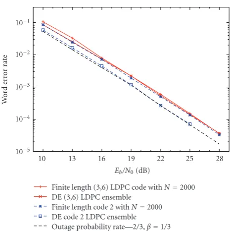
Finite length (3,6) LDPC code withN=2000 DE (3,6) LDPC ensemble
Finite length code 2 withN=2000 DE code 2 LDPC ensemble
Outage probability rate—2/3,β=1/3
Figure8: Density evolution of full-diversity LDPC ensembles with maximum coding rateRc=2/3 with iterative decoding on a MARC.
Eb/N0is the average information bit energy-to-noise ratio on theS1 -D,S2-D, andR-Dlinks.
Note that the message densities propagating from bits of the class2i1 do not contain a channel observation μ1(x)because these information bits are punctured.
Proof. SeeAppendix B.
7. Numerical Results
7.1. Full-Diversity LDPC Ensembles. We evaluated the finite length performance of full-diversity LDPC codes and the asymptotic performance by applying DE on the proposed code construction. The parity-check matrix (A.7) is used by the destination to decode the information bits. This paper focuses on full diversity, rather than coding gain. Therefore, one of the codes is a simple regular (3, 6) LDPC code. This means that all the random matrices in (A.7) are randomly generated satisfying an overall row weight of 6 and an overall column weight of 3. This matrix corresponds to a coding rate of 0.5, but because [2i1 2i2] are punctured, the actual coding rate isRc = 2/3. The other code, that is, simulated
and is denoted ascode 2is an irregular (λ(x),ρ(x)) LDPC ensemble [22] with left and right degree distributions given by the polynomials
λ(x)=0.285486x+ 0.31385x2+ 0.199606x7+ 0.201058x14,
ρ(x)=x8.
(44)
We studied the following scenario.
(i) TheS1-D,S2-D, andR-Dlinks have the same average SNR.
(ii) TheS1-RandS2-Rlinks are perfect.
(iii) The coding rate isRc=2/3 and the cooperation level
isβ=2/3.
Figure 8 shows the main results: the word error rate
(WER) of a regular (3, 6) LDPC ensemble and of an irregular (λ(x),ρ(x)) LDPC ensemble, which are both of full diversity. It is clear that the DE results are a lower bound on the actual word error rates (a tight lower bound for the regular code and a less tight lower bound for the irregular code). The word error rate of a regular (3, 6) LDPC code is only about 1.5 dB worse than the outage probability. The irregular LDPC code is only slightly better than the regular (3, 6) LDPC code in terms of word error rate.
7.2. Full-Diversity RA Codes with Improved Coding Gain.
Another technique, suggested in [17], that improves the coding gain is called doping. For all the Rootcheck based LDPC codes the reliability of the messages exchanged by the belief propagation algorithm can be improved by increasing the reliability of parity bits (which are not protected by rootchecks). In fact the LLR values of the messages exchanged by the belief propagation algorithm are in the form [17]:
Λm l ∝
B
i=1
aiα2i +η, (45)
whereαiare the fading coefficients,aiare positive constants,
andη represents the noise. The higher the coefficients ai,
the more reliable are the LLR messages. Since the output messages of the check node are limited by the lowest LLR values of the incoming messages, that is, the messages coming from parity bits, the doping technique aims to increase those values. The least reliable variable nodes are the parity bits sent on a channel in a deep fade.
In case of block BEC, consider the parity bits sent on a channel with fading coefficientα1 = 0 and suppose that all the other fading coefficients areαi= ∞withi /=1. Consider
the parity-check matrix (A.7). The doping technique consists in fixing the random matrix H1p1 such that, under BP, all
the variable nodes can be recovered after a certain number of iterations. This is equivalent to having reliable parity bits, that is, connected to rootchecks of a certain order, and it guarantees to increase the coefficientsai.
10−5
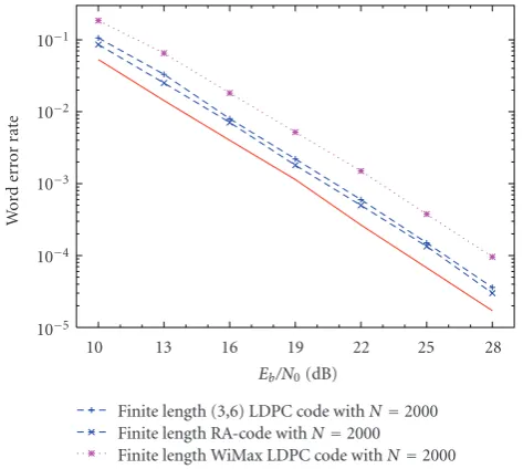
Finite length (3,6) LDPC code withN=2000 Finite length RA-code withN=2000
Finite length WiMax LDPC code withN=2000 Outage probability rate—2/3,β=1/3
Figure9: Comparison of proposed code construction with results from literature.Eb/N0is the average information bit energy-to-noise
ratio on theS1-D,S2-D, andR-Dlinks.
Figure 9reports the simulation results for a regular RA code
that show a 0.5 dB improvement compared to the proposed regular (3,6) code. Together with the fact that this simple code is now linear-time encoding, this result is impressive because we have lowered the complexity and improved the performance at the same time. As a benchmark the outage probability has been plotted. We have also included the best known LDPC code for the MARC in literature: the rate 2/3 network code proposed in [16]; it reports a loss of almost 2.5 dB wrt. the proposed full-diversity RA code.
8. Conclusions and Remarks
We have studied LDPC codes for the multiple access relay channel in a slowly varying fading environment under iterative decoding. LDPC codes must be carefully designed to achieve full diversity on this channel and network coding must be applied to increase the achievable coding rate to a maximum rateRcmax = 2/3. Combining network coding with of full diversity channel coding gave rise to a new family of semirandom full-diversity joint network-channel LDPC codes for all rates not exceedingRcmax =2/3. A code that is only 1.5 dB away from the outage probability limit has been presented.
For a block fading channel with several fading states per codeword, it has been pointed out that the poor reliability of the parity bits in full-diversity LDPC codes (where especially the information bits are well protected) causes the actual gap with the outage probability limit. We increased the reliability of the parity bits by using a repeat-accumulate structure and have improved the coding gain of the presented code construction for the MARC.
Appendices
A. Full-Diversity Parity-Check Matrices
1i1 1p1 1i2 1p2 2i1 2i2 c(3)
B. Proof of
Proposition 3
Equations (33)–(40) are directly derived from the local neighborhood trees (see e.g., Figures 11 and 12). The proportionality factors(35)–(40)can easily be determined by analyzing the Tanner graph. LetT denote the total number of edges between the variable nodes(1i1−1p1)and the check nodes1c.Figure 10illustrates how f1p1candf1i1care obtained:
(a)The fraction of check nodes connected to(i−1)edges ofTisρ◦i(N/8). A similar reasoning proves(B.2).
(b)The fraction of edgesT connecting1p1 to1cis f1p1c
and the fraction of edgesTconnecting1i1to1cis f1i4c.
Note that in the first iteration, a1
1(x), f11(x), k11(x), and b1
1(x)are equal toμ1(x), because the received messages come from check nodes where one of the leaves corresponds to a punctured information bit (so that their message density is a Dirac function onLLR=0). Therefore, the message densities coming from the check nodes are also Dirac functions on
LLR = 0. (The output of a check node y is determined through its inputsxi,i=1· · ·dc−1via the following formula:
th(y/2)=!dc−1
i=1 th(xi/2). If one of the inputsxiis always zero
because its distribution is a Dirac function onLLR=0, then the outputywill always be zero, so that its distribution will also be a Dirac function on LLR = 0.) Butq1(x)andg1(x) are different from a Dirac function onLLR = 0 after the first iteration, so that the next iteration alsol1(x) becomes different from a Dirac function onLLR=0.
Figure 10: Part of the compact graph representation of the Tanner graph of proposed code construction. The number of edges connecting (1i1−1p1) to1cisT. The number of edges connecting
Figure11: Local neighborhood of a bit node of the class 1i1. This
tree is used to determineam+1 1 (x).
Figure12: Local neighborhood of a bit node of the class 1i1. This
The factor0.5 in (42) and(43) takes into account that c(3) counts N/4 variable nodes while 3c and 4c count only N/8parity check equations. Solving together(40)–(43), it is possible to prove that for any degree distribution
f3cc(3)=f4cc(3)=
1
2. (B.4)
Acknowledgments
D. Capirone wants to acknowledge professor Benedetto for helpful and stimulating discussions. This work was supported by the European Commission in the framework of the FP7 Network of Excellence in Wireless COMmunications NEWCOM++ (Contract no. 216715).
References
[1] A. Sendonaris, E. Erkip, and B. Aazhang, “User cooperation diversity—part I: system description,”IEEE Transactions on Communications, vol. 51, no. 11, pp. 1927–1938, 2003. [2] A. Sendonaris, E. Erkip, and B. Aazhang, “User cooperation
diversity—part II: implementation aspects and performance analysis,”IEEE Transactions on Communications, vol. 51, no. 11, pp. 1939–1948, 2003.
[3] J. N. Laneman, D. N. C. Tse, and G. W. Wornell, “Cooperative diversity in wireless networks: efficient protocols and outage behavior,”IEEE Transactions on Information Theory, vol. 50, no. 12, pp. 3062–3080, 2004.
[4] T. Hunter, Coded cooperation: a new framework for user cooperation in wireless systems, Ph.D. dissertation, University of Texas at Dallas, Richardson, Tex, USA, 2004.
[5] E. Van Der Meulen, “Three-terminal communication chan-nels,”Advances in Applied Probability, vol. 3, no. 1, pp. 120– 154, 1971.
[6] T. M. Cover and A. A. Gamal, “Capacity theorems for the relay channel,”IEEE Transactions on Information Theory, vol. 25, no. 5, pp. 572–584, 1979.
[7] E. Biglieri, Coding for the Wireless Channel, Springer, New York, NY, USA, 2005.
[8] D. Duyck, J. Boutros, and M. Moeneclaey, “Low-density graph codes for slow fading relay channels,” IEEE Transactions on Information Theory, http://telin.ugent.be/∼ dduyck/publica-tions/paper ldpc cooperative.pdf. In press.
[9] T. Richardson and R. Urbanke, Modern Coding Theory, Cambridge University Press, Cambridge, UK, 2008.
[10] J. Boutros, G. I. F`abregas, and E. Calvanese-Strinati, “Analysis of coding on non-ergodic channels,” inProceedings of the Aller-ton Conference on Communication, Control and Computing, 2005.
[11] R. Knopp and P. A. Humblet, “On coding for block fading channels,”IEEE Transactions on Information Theory, vol. 46, no. 1, pp. 189–205, 2000.
[12] C. Hausl,Joint network-channel coding for wireless relay net-works, Ph.D. dissertation, Technische Universit¨at M¨unchen, M¨unchen, Germany, November 2008.
[13] R. Ahlswede, N. Cai, S.-Y. R. Li, and R. W. Yeung, “Network information flow,”IEEE Transactions on Information Theory, vol. 46, no. 4, pp. 1204–1216, 2000.
[14] C. Hausl and P. Dupraz, “Joint network-channel coding for the multiple-access relay channel,” inProceedings of the 3rd Annual IEEE Communications Society on Sensor and Ad Hoc Communications and Networks (Secon ’06), vol. 3, pp. 817–822, September 2006.
[15] C. Hausl, F. Schreckenbach, I. Oikonomidis, and G. Bauch, “Iterative network and channel decoding on a tanner graph,” inProceedings of the Allerton Conference on Communication, Control and Computing, 2005.
[16] L. Chebli, C. Hausl, G. Zeitler, and R. Koetter, “Cooperative uplink of two mobile stations with network coding based on the WiMax LDPC code,” in Proceedings of the IEEE Global Telecommunications Conference (GLOBECOM ’09), 2009. [17] J. J. Boutros, “Diversity and coding gain evolution in graph
codes,” inProceedings of the Information Theory and Applica-tions Workshop (ITA ’09), pp. 34–43, February 2009.
[18] D. Capirone, D. Duyck, and M. Moeneclaey, “Repeat-accumulate and Quasi-Cyclic Root-LDPC codes for block fading channels,”IEEE Communications Letters. In press. [19] A. Lapidoth, “The performance of convolutional codes on
the block erasure channel using various finite interleaving techniques,”IEEE Transactions on Information Theory, vol. 40, no. 5, pp. 1459–1473, 1994.
[20] R. J. McEliece and W. E. Stark, “Channels with block interference,”IEEE Transactions on Information Theory, vol. 30, no. 1, pp. 44–53, 1984.
[21] T. J. Richardson, M. A. Shokrollahi, and R. L. Urbanke, “Design of capacity-approaching irregular low-density parity-check codes,”IEEE Transactions on Information Theory, vol. 47, no. 2, pp. 619–637, 2001.
[22] J. J. Boutros, A. G. I. F`abregas, E. Biglieri, and G. Z´emor, “Low-density parity-check codes for nonergodic block-fading channels,”IEEE Transactions on Information, vol. 56, no. 9, pp. 4286–4300, 2009.
[23] J. Thorpe, “Low-density parity-check (LDPC) codes con-structed from protographs,”JPL INP Progress Report, vol. 42, no. 154, pp. 1–7, 2003.
[24] W. Ryan and S. Lin, Channel Codes, Classical and Modern, Cambridge University Press, Cambridge, UK, 2009.
[25] D. Tse and P. Viswanath,Fundamentals of Wireless Communi-cation, Cambridge University Press, Cambridge, UK, 2005. [26] G. I. F`abregas, “Coding in the block-erasure channel,”IEEE
Transactions on Information Theory, vol. 52, no. 11, pp. 5116– 5121, 2006.
[27] E. Biglieri, J. Proakis, and S. Shamai, “Fading channels: information-theoretic and communications aspects,” IEEE Transactions on Information Theory, vol. 44, no. 6, pp. 2619– 2692, 1998.
[28] G. Ungerboeck, “Channel coding with multilevel/phase sig-nals,”IEEE Transactions on Information Theory, vol. 28, no. 1, pp. 55–67, 1982.
[29] M. Abramowitz and I. Stegun, Handbook of Mathematical Functions: with Formulas, Graphs, and Mathematical Tables, Courier Dover, New York, NY, USA, 1965.
[30] D. Duyck, D. Capirone, M. Moeneclaey, and J. J. Boutros, “A full-diversity joint network-channel code construction for cooperative communications,” inProceedings of the IEEE International Symposium on Personal, Indoor and Mobile Radio Communications (PIMRC ’09), 2009.
[32] H. Jin, T. Richardson, F. Technol, and N. Bedminster, “Block error iterative decoding capacity for LDPC codes,” in Pro-ceedings of the IEEE International Symposium on Information Theory (ISIT ’05), pp. 52–56, 2005.