R E S E A R C H
Open Access
Relay on-off threshold for NDF protocol with
distributed orthogonal space-time block codes
Dong-Sup Jin
1, Xianglan Jin
2, Jong-Seon No
1and Dong-Joon Shin
3*Abstract
In this article, a relay on-off threshold (ROT) based on symbol error rate is derived for the cooperative communication networks with multiple antennas, where the non-orthogonal decode-and-forward (NDF) protocol with source antenna switching and linear combining decoding are used as the relaying protocol and decoding scheme, respectively. The optimal ROT for the cases using distributed orthogonal space-time block codes is derived for high signal to noise ratio (SNR) region and also a suboptimal ROT is provided for low SNR region. Finally, the diversity order of the NDF protocol using the relay on-off scheme with the proposed ROT is derived and its performance is verified through numerical analysis.
Keywords: Cooperative communication networks, Cooperative diversity, Distributed orthogonal space-time block codes (DOSTBCs), Linear combining (LC) decoding, Non-orthogonal decode-and-forward (NDF), Relay on-off threshold (ROT)
Introduction
Attenuation and fading in the multipath wireless environ-ment make it difficult for a receiver to correctly decode a received signal. Therefore, replicas of a transmitted sig-nal are sent to the receiver to improve the detection performance.
Tarokh et al. [1] proposed space-time codes (STCs) to achieve transmit diversity and their design criteria. Alam-outi code was proposed in [2], which was extended to orthogonal space-time block codes (OSTBCs) in [3]. Also, the symbol error rate (SER) and bit error rate (BER) of OSTBCs for quadrature amplitude modulation (QAM) were derived in [4,5], respectively.
The cooperative diversity which is obtained by uti-lizing relays between source and destination has been actively studied since Cover and El Gamal’s [6] work. Laneman et al. [7] developed some cooperative diver-sity schemes based on repetition codes and analyzed their performance, and Wang et al. [8] developed a good demodulation scheme for the protocol proposed in [7].
*Correspondence: [email protected]
3Department of Electronic Engineering, Hanyang University, Seoul 133-791, Korea
Full list of author information is available at the end of the article
Recently, various results on how to select the best relay(s) among multiple relays have been reported. Bletsas et al. [9] proposed an opportunistic relaying which selects a relay only by using local channel information. Jing and Jafarkhani [10] proposed a multiple-relay selection scheme for the amplify and forward (AF) protocol and Yi and Kim [11] analyzed the diversity order of the decode-and-forward (DF) protocol with relay selection.
On the other hand, a relay on-off scheme for the DF protocol according to the channel state was proposed in [7]. Recently, another relay selection scheme based on the relay on-off threshold (ROT) for the DF protocol was also proposed in [12]. In both schemes, if the received signal to noise ratio (SNR) at the relay is larger than the ROT, the relay transmits a signal and otherwise, the relay does not transmit a signal. However, the optimal ROT was not derived analytically.
For the orthogonal DF (ODF) protocol and binary phase shift keying (BPSK), Siriwongpairat et al. [13] derived the ROT over the Rayleigh fading channel and Ikki and Ahamed [14] derived the ROT over the Nakagami-m
fading channel. However, until now, forM-QAM and non-orthogonal DF (NDF) protocol in which a source also transmits a signal when a relay transmits a signal, the ROT has not been investigated.
It is well known that source antenna switching (SAS) can gain additional diversity for the NDF protocol by using different antennas at the source in the first and second phases [15], and the maximal likelihood (ML) decod-ing is impractical because its computational complex-ity increases exponentially with the signal constellation size. Therefore, we will use the low-complexity decoding scheme for OSTBCs given in [16,17], which is called linear combining (LC) decoding.
In this article, an ROT is derived for the NDF proto-col with distributed orthogonal space-time block codes (DOSTBCs) andM-QAM such that the SER of LC decod-ing is minimized over the Rayleigh faddecod-ing channel. Until now, this kind of ROT has not been investigated yet. And, the diversity order of the proposed relay on-off scheme is derived.
This article is organized as follows. In Section “Sys-tem models and LC decoding”, the sys“Sys-tem models and LC decoding are described and in Section “ROT and diversity analysis”, the ROT based on SER is derived and the diver-sity order of the proposed relay on-off scheme is analyzed. In Section “Numerical analysis”, the SER performance of the proposed relay on-off scheme is evaluated through numerical analysis and the concluding remarks are given in Section “Conclusion”.
Throughout this article, the following notations are used. E[·] denotes the expectation. X ∼ CN(0,σ2) denotes the complex Gaussian random variable with zero mean and variance σ2/2 for each of real and imaginary parts. For a complex number, | · |, (·)∗, R(·), and I(·) denote the magnitude, the complex conjugate, the real part, and the imaginary part, respectively. CM×N and (·)T denote the set ofM×N complex matrices and the transpose of a matrix, respectively.
System models and LC decoding
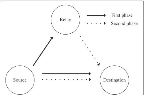
For the three-terminal cooperative communication net-work in Figure 1, it is assumed that source (S), relay (R), and destination (D) can have multiple antennas and the channels are quasi-static Rayleigh fading ones. Since non-orthogonal transmission is assumed, both source and relay transmit signals in the second phase. It is also assumed that the destination has the perfect channel state information (CSI) ofS–DandR–Dchannels and the relay knows the CSI of S–Rchannel and the mean and vari-ance ofS–DandR–Dchannel coefficients. For simplicity, Gray-mappedM-QAM is assumed.
If the SNR at the relay is larger than an ROTTin the DF protocol, the relay transmits a signal and otherwise, the relay does not transmit a signal. Note that it is assumed that the source and destination know whether the relay
is on or off. In the cooperative communication network, if the source uses the same antenna in the first and sec-ond phases, the S–D and S–R channel coefficients for these two phases become identical. Therefore, in order to increase the diversity order, it is assumed that the SAS [15] is used.
System models of NDF protocol
It is assumed that the numbers of antennas of the source, relay, and destination areMS,MR, andMD, respectively. Let x be the message vector consisting of L indepen-dent symbols.CS,1(x) ∈CT×MS denotes the codeword of OSTBC transmitted from the source, whereT denotes the number of transmissions at each source antenna. In the first phase, the received signal matricesYRandYD1at the relay and destination can be written as
YR=√p1ρCS,1(x)H+NR (1)
YD1=√p1ρCS,1(x)G1+ND,1 (2)
whereH∈CMS×MRandG1∈CMS×MDare theS–RandS– Dchannel matrices, andNR∈CT×MRandND,1∈CT×MD are the noise matrices at the relay and destination. Note thatp1ρis the power of the signal from the source andρis a parameter linearly proportional to the average transmit SNR.
In the second phase, letxRdenote the decoded message vector at the relay andCS,2(x) ∈ CT×MS andCR,2(xR) ∈ CT×MR denote the codewords of OSTBCs corresponding
Relay
Source Destination
First phase Second phase
toxandxRtransmitted from the source and relay, respec-tively. When the relay is on, the received signal at the destination in the second phase is given as
YD2=
√
p2ρCS,2(x) √p3ρCR,2(xR) G2 F
+ND,2
(3)
whereG2 ∈ CMS×MD andF ∈ CMR×MD are theS–Dand R–Dchannel matrices, and ND,2 ∈ CT×MD is the noise matrix at the destination. Note thatp2ρ andp3ρ denote the signal powers from the source and relay in the second phase, respectively. ThenCS,2(x)CR,2(xR)
also forms an OSTBC if xR = x. The entries of H, G1, G2, and F are independently distributed asCN(0,σSR2),CN(0,σSD2 ),
CN(0,σSD2 ), andCN(0,σRD2 ), respectively. The entries of NR,ND,1, andND,2arei.i.d. random variables distributed asCN(0, 1).
When the relay is off, the received signal at the destina-tion in the second phase is given as
YD2=√p2ρCS,2(x)G2+ND,2. (4)
Therefore, by using (2), (3), and (4), the received signal matrix can be expressed as
YD=
YD1 YD2
. (5)
LC decoding
The optimal ML decoding at the destination is done by selectingxˆsuch as
ˆ
x=arg max
x logPr(YD|x)
=arg max
x log
xR
Pr(xR|x)Pr(YD|xR,x).
Since, the complexity of ML decoding increases expo-nentially to the constellation size and the analysis of ML decoding is very difficult, simple and practical LC decod-ing [16,17] will be considered in this article. It is clear that LC decoding is equivalent to ML decoding for OST-BCs but it is not true for DOSTOST-BCs because the relay may transmit erroneously decoded symbols.
For the cooperative communication network, the LC decoding operates twice. First, the LC decoding is done forYD1andYD2, respectively, before the decision onxis
made at the destination. Then, the destination combines the decoder outputs forYD1andYD2. Finally, the decision is made forxby using this combined output.
ROT and diversity analysis
If theS–Rchannel orR–Dchannel is not good enough for the reliable communication, a relay cannot help the des-tination that much. Therefore, it is important to decide whether a relay should be used or not depending on the states ofS–RandR–Dchannels. In general, a relay is used in the DF protocol only when the received SNR at the relay is greater than the ROT. If the relay correctly decodes the information, it can be thought as a virtual antenna of the source and the diversity gain can be obtained even though theR–Dchannel is not good. Therefore, an ROT can be determined only by monitoringS–Rchannel state [7,13,14].
If the ROT is too low, the relay may transmit many erro-neous data under the badS–Rchannel condition, which causes many decoding errors at the destination. On the contrary, if the ROT is too high, the relay is rarely used and the cooperative diversity cannot be achieved. Therefore, the optimal ROT for the NDF protocol with DOSTBCs andM-QAM is derived in this section.
It can be assumed that, in high SNR region, only one symbol error occurs amongLsymbols in a codeword and further a symbol error is caused by one-bit error. Let
u = MS
i=1 MR
j=1|hi,j|2, g1 = Mi=1S MD
j=1|g1,i,j|2, g2 = MS
i=1 Mj=1D|g2,i,j|2, andw = iM=1D Mj=1R |fi,j|2, wheregk,i,j denotes the channel coefficient between the ith source antenna and thejth destination antenna in thekth phase, andhi,j denotes the channel coefficient between the ith source antenna and thejth relay antenna, andfi,jdenotes the channel coefficient between theith relay antenna and thejth destination antenna. Clearly,u, g1, g2, and ware Erlang distributed [18].
ROT (general expression)
Pe(T)
=Pr(symbol error|relay off)Pr(relay off)
Case 1
+Pr(symbol error |relay on, no symbol error at the relay)Pr(relay on, no symbol error at the relay) Case 2
+Pr(symbol error|relay on, symbol error at the relay)Pr(relay on, symbol error at the relay)
Case 3
. (6)
As SNR increases, the probability of Case 3 in (6) can be approximated as
Pr(symbol error|relay on, symbol error at the relay)Pr(relay on, symbol error at the relay)
Case 3
≈Pr(symbol error|relay on, one bit error at the relay)Pr(relay on, one bit error at the relay)
Case 3
. (7)
The pdf of Erlang random variableuis given as
f(u)= λe
−λu(λu)MSMR−1
(MSMR−1)!
(8)
whereλ = 1/σSR2. LetPe1be the SER at the destination when the relay is off, Pe2be the SER at the destination when the relay is on and no decoding error occurs at the relay, andPe3be the SER at the destination when the relay is on and the decoding error occurs at the relay. Using (6) and (7), the SER at the destination is derived as
Pe(T)=Pe1
T
p1ρ
0
f(u)du+Pe2
∞
T p1ρ
1−4
1− √1
M
Q
3p1ρu M−1
L
probability that no symbol error occurs at the relay f(u)du
+Pe3
∞
T p1ρ
⎡ ⎣1−
1−4
1−√1
M
Q
3p1ρu M−1
L⎤
⎦
probability that symbol errors occur at the relay
f(u)du
≈Pe1
T
p1ρ
0
f(u)du+Pe2
∞
T p1ρ
1−4L
1−√1
M
Q
3p1ρu M−1
f(u)du
+Pe3
∞
T p1ρ
4L
1− √1
M
Q
3p1ρu M−1
≈one bit error probability at the relay
f(u)du (9)
wherePe3can be approximated as the symbol error prob-ability at the destination when one bit error causes one symbol error at the relay. Then, by solvingdPe(T)
T =
Since some approximations are used to derive the ROT, it is clearly suboptimal. However, through simulation, it will be shown that this ROT approaches the optimal ROT as SNR increases.
ROT for LC decoding
In this section, we derivePe1,Pe2, andPe3for LC decoding and obtain the ROT based on them.
Case (1) Relay is off:
Since only the source transmits signals, Pe1 can be written as [4]
whereddenotes the distance between one symbol point and the adjacent decision boundary in the rectangular QAM and the closed form ofPe1can be derived by the result in [19].
Case (2) Relay is on and no decoding error occurs at the relay:
Since the relay transmits correct data,Pe2can be written as [4]
and its closed form can be derived by the result in [19]. Case (3) Relay is on and the decoding error occurs at the relay:
Since Gray-mapped M-QAM is assumed, the SER is dominantly determined by the single-bit error at the relay as SNR increases. Also, the most frequent symbol error event at the relay is one symbol error amongLsymbols. Therefore,Pe3can be approximated as the SER at the des-tination when one-bit error occurs at the relay. Since the SER depends on the LC decoder output before the deci-sion is made, we confirm how the one bit error at the relay affects the LC decoder output at the destination and then derive the SER.
When the relay erroneously decodesxk toxk+2d, the LC decoder output sk for xk at the destination can be written as
Next, let us investigate the LC decoder outputsi,i =k for thexi which is not erroneously decoded at the relay. For OSTBCs, when the LC decoding is performed to the data symbolxi, the terms related to the other symbols are canceled out and thus the decoder output at the destina-tion becomes equivalent to (14). However, for DOSTBCs, if one bit error forxkoccurs at the relay, the terms related toxkpossibly affect the decoder output for the other sym-bol at the destination. Therefore, the decoder output forxi at the destination can be divided into two cases. First, the terms related toxkdo not affectsisuch as
si,R=R(si)=√ρ(p1g1+p2g2+p3w)R(xi)+R(ni) si,I=I(si)=√ρ(p1g1+p2g2+p3w)I(xi)+I(ni).
(15)
where ni is distributed as CN(0,p1g1 + p2g2 + p3w), g2,i,j ◦fl,k denotes eitherg2,i,jfl∗,k or g2,∗i,jfl,k depending on the used DOSTBC, andDis the set of indices of channel coefficients that are not canceled out due to one bit error forxk.
As an example, consider a DOSTBC using the following OSTBCs forMS=2 andMR=2
From the LC decoder outputs (13)–(16), we can check the error cases at the destination and then calculatePe3.
• The SER forxk(the error symbol at the relay) at the
destination;
First, we consider the case that the error occurs at the destination when decodingskin (13) and (14). Note
thatk is the index of the error symbol at the relay. – The error case that the destination decodes
R(xk)toR(xk)+2d
ofxkin this direction, the destination can
erroneously decodeR(xk)toR(xk)+2dwith
Note that this symbol error at the destination is the same as the symbol error at the relay. – The error case that the destination decodes
R(xk)toR(xk)−2d
with the following SER
Pe3,1=E
– The error case that the destination decodes
I(xk)toI(xk)±2d
destination with the following SER
Pe3,2=E
Note that the relay can erroneously decodesxkto
xk−2dorxk±j2d. However, the identical LC decoder
outputs to (13) and (14) are obtained since the rectangular QAM is considered. Thus, for those cases, we can also obtainPe3,1,Pe3,1,andPe3,2similarly.
Therefore, when one bit error occurs forxkat the
relay, the SER forxkat the destination is given as the
linear combination ofPe3,1,Pe3,1,andPe3,2, that is
Perror,k=Pe3,1+βPe3,1+γkPe3,2 (21)
whereβandγkare constants determined by the constellation and structure of DOSTBCs. The coefficient ofPe3,1in (21) is 1 becausePe3,1can be
regarded as the probability that the same error at the relay also occurs at the destination.
• The SER forxi,i=k(no-error symbol at the relay); The SER forxican be obtained according to the LC
decoder output in (15) and (16).
– The case that LC decoder output forxiis (15) the destination can erroneously decodeR(xi)
toR(xi)+2dorR(xi)−2d. Also, if
the destination can erroneously decodeI(xi)
– The case that LC decoder output forxiis (16)
Similarly to the previous case, we can obtain the following SER by considering (16)
Pe3,3=
E
⎡ ⎣Q
⎛ ⎝d
√2ρ
p1g1+ (i,j)/∈Dp2|g2,i,j|2+ (l,k)/∈Dp3|f2,l,k|2+ (i,j),(l,k)∈D|√p2g2,i,j⊕√p3fl,k|2
!
p1g1+p2g2+p3w
⎞ ⎠ ⎤
⎦ (22)
where|√p2g2,i,j⊕√p3fl,k|2denotes one of |√p2g2,i,j+ √p3fl,k|2,|√p2g2,i,j− √p3fl,k|2, |√p2g2,i,j+j√p3fl,k|2, and
|√p2g2,i,j−j√p3fl,k|2depending on the
structure of DOSTBCs like the operator◦in (16). However, all possiblePe3,3’s depending
on⊕have the same value because each channel coefficient is a complex Gaussian random variable with zero mean. Thus, we can see that⊕can be replaced with the addition without changing the result. Finally, the SER forxi,i=kcan be expressed as
Perror,i=γiPe3,2+δiPe3,3 (23)
whereγiandδiare constants determined by the constellation and structure of DOSTBCs. Since the LC decoder output forxicannot become (15) and (16)
simultaneously, for eachPerror,i, ifγiis not zero,δi
should be zero and ifδiis not zero,γishould be zero.
• The SER at the destination when one bit error occurs at the relay (Pe3);
When one-bit error forxkoccurs at the relay, the
SER at the destination can be expressed as
Pe3= i∈{1,...,L} Perror,i
L =
Perror,k+ Li∈{1,...,L},i=kPerror,i
L
= Pe3,1+βP
e3,1+γkPe3,2+ Li∈{1,...,L},i=kγiPe3,2+ Li∈{1,...,L},i=kδiPe3,3
L .
(24)
By plugging Pe1, Pe2, and Pe3 to (10), we can obtain the ROT. In fact, we cannot derive or prove something not because it is complicated but because it is hard or intractable. However, the ROT for high SNR region can be derived by the following approximation.
Since the direct approximation ofPe3,1from (18) is too complicated, we use the assumption that the effect of noise is negligible in high SNR region and thus (13) is approximated as
sk,R≈√ρ
*
p1g1+p2g2+p3w
+
Then, the error can occur ifsk,R > √ρ{p1g1+p2g2+
By using the pdf and the cumulative distribution func-tion (cdf ) of the sum of independent and nonidenti-cal Erlang random variables in [18], P˜e3,1 can be easily calculated.
As SNR increases,Pe3,1,Pe3,2, andPe3,3in (24) become negligible compared toP˜e3,1and thusPe3becomes close toP˜e3,1/L. SincePe2 in (12) decreases much faster than Pe1in (11) as SNR increases, onlyPe1andP˜e3,1/Lbecome dominant in the numerator and denominator in (10), respectively. Finally, in high SNR region, the ROT in (10) is simplified as
Decision of suboptimal ROT in low SNR region
In the previous section, an ROT was derived only for high SNR region because Pe3 cannot be derived in low SNR region. Thus, for the whole SNR region including low SNR region, the ROT should be determined.
The ROT in (10) is approximated as (27) by using the following approximation
However, the ROT in (27) cannot be calculated in low SNR region becauseP˜e3,1/Lbecomes less thanPe1as SNR decreases. The argument of Q−1(·) can be greater than 1 when the R–D channel state is not better than the
S–Dchannel state such as(ρ,ρ,ρ). Therefore, a subopti-mal ROT for low SNR region is heuristically obtained by giving a bias such as usingP˜e3,1/L+Pe1instead ofP˜e3,1/L
Note that, as SNR increases, the ROT in (29) becomes identical to the ROT in (27) becausePe1goes to zero.
Diversity analysis
In this section, the diversity order of NDF protocol with the proposed relay on-off scheme is derived when DOST-BCs and LC decoding are used.
When the relay is off, the transmit signals in the first
and second phases form an OSTBC
$
CS,1(x) 0 0 CS,2(x)
(
and when the relay is on, the transmit signals in the first and second phases form a DOSTBC
$
CS,1(x) 0 0 0 CS,2(x) CR,2(x)
(
.
Since the ranks of their difference matrices are 2MSand 2MS+MR, respectively, and the destination hasMD anten-nas, in high SNR region, Pe1 and Pe2 are proportional toρ−2MSMDandρ−{MSMD+(MS+MR)MD}, respectively. Also, Pe1/
0
4 1−1/√M!P˜e3,1
1
in (27) can be approximated
ascρ−2MSMD, wherecis a positive constant.
where(λT/ρ)MSMRPe1/(MSMR)! is dominant becauseT/ρ <<1
asρincreases. Using (30) and (33), the diversity order of the first term in (31) is obtained as 2MSMD+MSMR.
in (31). Therefore, it is clear that the diversity order of the sec-ond term in (31) is 2MSMD+MRMDbecausePe2 term in (31) is upper bounded by
Pe3 first term in (34) becomes dominant asρincreases. By plugging (30) into (34), this factor becomes as follows.
e− δρ2+λ gible as SNR increases, the diversity order of (34) is given as 2MSMD+MSMR.
In conclusion, the diversity orderdLCof NDF protocol with
the LC decoding and the proposed relay on-off scheme is given as
dLC=min(2MSMD+MSMR, 2MSMD+MRMD). (36)
Note that the diversity order 2MSMD + min(MSMR,
MRMD)is identical to the full diversity order of NDF protocol
with SAS [15].
Numerical analysis
For the simulation, it is assumed that the transmit signal power in the first phase is the same as the sum of transmit signal
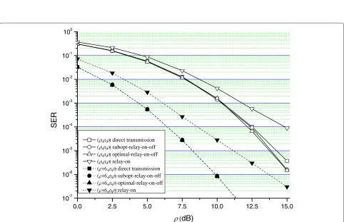
powers from the source and relay in the second phase, and the transmit signal power of the relay is the same as that of the source in the second phase.(x,y,z) denotes the average received SNRs in dB ofS–D,S–R, andR–Dchannels, respec-tively. For example,(ρ,ρ,ρ+6)means that the average received SNR of R–D channel is larger than those of S–R and S–D channels by 6 dB. For all simulations, 16QAM is used.
To confirm the diversity order, whenMS,MR,MD ≥2,
sim-ulation must be performed in very high SNR region, which requires too long time. Instead, simulation has been performed for the single-antenna case (MS = MR = MD = 1). For Alamouti code in the second phase. The ROT for the single-antenna case can also be easily obtained from (27) and (29).
Figures 2 and 3 compare the performance of NDF protocol with various relay schemes. We do not consider the case that theS–Rchannel state is better than the other channel states because the relay always tends to be on. The performance of the proposed optimal and suboptimal relay on-off schemes and the conventional relay scheme are denoted by ‘optimal-relay-on-off ’, ‘subopt-relay-on-‘optimal-relay-on-off ’, and ‘relay-on’, respectively. In other words, ‘relay-on’ means that the relay always transmits signal. The ‘direct transmission’ implies that the relay is always off. The optimal relay on-off scheme uses the optimal ROT which is determined by extensive simulation and the suboptimal relay on-off scheme uses the ROT in (29).
Figure 2 shows that the SER performance of the relay-on scheme becomes worse as theR–Dchannel state becomes bet-ter and thus, in this case, the relay on-off scheme is vital to improve the LC decoding performance. For the case of(ρ+ 6,ρ,ρ)in Figure 3, it can be seen that the performance of the relay on-off scheme is almost identical to that of the direct transmission untilρ=12.5 dB, which is becausePe1≤Pe2and the relay is always off. Therefore, the ROT should be infinite, as given by (10). Also, we can see that the analytical diversity results in Section Diversity analysis are well matched with the simulation results in Figures 2 and 3, and the suboptimal ROT works well in low SNR region as well as in high SNR region.
Figures 4 and 5 compare the performance of NDF protocol with various relay schemes whenMS=MR=MD=2 and the
0 5 10 15 20 25 10-4
10-3 10-2 10-1 100
direct transmission ( )subopt-relay-on-off ( )optimal-relay-on-off ( )relay-on
( +6)subopt-relay-on-off ( +6)optimal-relay-on-off ( +6)relay-on
SE
R
(dB)
Figure 2Performance comparison of NDF protocol with various relay schemes for single-antenna case using 16QAM under variousR–D channel states.
0 5 10 15 20 25
10-5 10-4 10-3 10-2 10-1 100
SER
(dB) ( )direct transmission
( )subopt-relay-on-off ( )optimal-relay-on-off ( )relay-on
( +6 )direct transmission ( +6 )subopt-relay-on-off ( +6 )optimal-relay-on-off ( +6 )relay-on
0.0 2.5 5.0 7.5 10.0 12.5 15.0 10-6
10-5 10-4 10-3 10-2 10-1 100
direct transmission ( )subopt-relay-on-off ( )optimal-relay-on-off ( )relay-on
( +6)subopt-relay-on-off ( +6)optimal-relay-on-off ( +6)relay-on
SER
(
dB)
Figure 4Performance comparison of NDF protocol with various relay schemes for two-antenna case using 16QAM under variousR–D channel states.
0.0 2.5 5.0 7.5 10.0 12.5 15.0
10-7 10-6 10-5 10-4 10-3 10-2 10-1 100
( )direct transmission ( )subopt-relay-on-off ( )optimal-relay-on-off ( )relay-on
(+6 )direct transmission (+6 )subopt-relay-on-off (+6 )optimal-relay-on-off (+6 )relay-on
SER
(
dB)
Conclusion
In this article, an ROT was analytically derived for NDF pro-tocol with DOSTBCs and SAS in high SNR region, where LC decoding was considered because it has low complexity and good performance. Through the diversity analysis, it was con-firmed that the NDF protocol with the proposed relay on-off scheme can achieve the full diversity. For low SNR region, the suboptimal ROT was provided and the simulation results con-firmed that this suboptimal ROT works well in whole SNR region. It is left as a future work to derive the optimal ROT for the cooperative communication networks with multiple relays by using a similar method to one proposed in this article.
Competing interests
The authors declare that they have no competing interests.
Acknowledgements
This research was supported by the KCC (Korea Communications Commission), Korea, Under the R&D program supervised by the KCA (Korea Communications Agency) (KCA-2012-08-911-04-003) and the National Research Foundation of Korea (NRF) grant funded by the Korea government (MEST) (No. 2012-0000186).
Author details
1Department of Electrical Engineering and Computer Science, INMC, Seoul
National University, Seoul 151-744, Korea.2Department of Information and Communication Engineering, Dongguk University-Seoul, Seoul 100-715, Korea.3Department of Electronic Engineering, Hanyang University, Seoul 133-791, Korea.
Received: 8 June 2012 Accepted: 4 September 2012 Published: 26 September 2012
References
1. V Tarokh, N Seshadri, A Calderbank, Space-time codes for high data rate wireless communication: performance criterion and code construction. IEEE Trans. Inf. Theory.44, 744–765 (1998). doi:10.1109/18.661517
2. SM Alamouti, A simple transmit diversity technique for wireless communications. IEEE J. Sel. Area Commun.16, 1451–1458 (1998). doi:10.1109/49.730453
3. V Tarokh, H Jafarkhani, A Calderbank, Space-time block codes from orthogonal designs. IEEE Trans. Inf. Theory.45, 1456–1467 (1999). doi:10.1109/18.771146
4. S Kim, I Kang, J No, Symbol error probability of orthogonal space-time block codes with QAM in slow Rayleigh fading channel. IEICE Trans. Commun.87-B, 97–103 (2004)
5. S Kim, J Yang, J No, Exact bit error probability of orthogonal space-time block codes with quadrature amplitude modulation. J. Commun Netw.
10, 253–257 (2008)
6. T Cover, A Gamal, Capacity theorems for the relay channel. IEEE Trans. Inf. Theory.IT-25, 572–584 (1979). doi:10.1109/TIT.1979.1056084
7. J Laneman, D Tse, G Wornell, Cooperative diversity in wireless networks: efficient protocols and outage behavior. IEEE Trans. Inf. Theory.
50, 3062–3080 (2004). doi:10.1109/TIT.2004.838089
8. T Wang, A Cano, G Giannakis, J Laneman, High-performance cooperative demodulation with decode-and-forward relays. IEEE Trans. Commun.
55, 1427–1438 (2007). doi:10.1109/TCOMM.2007.900631
9. A Bletsas, A Khisti, D Reed, A Lippman, Simple cooperative diversity method based on network path selection. IEEE J. Sel. Area Commun.
24, 659–672 (2006). doi:10.1109/JSAC.2005.862417
10. Y Jing, H Jafarkhani, Single and multiple relay selection schemes and their achievable diversity orders. IEEE Trans. Wirel. Commun.
8, 1414–1423 (2009). doi:10.1109/TWC.2008.080109
11. Z Yi, I Kim, Diversity order analysis of the decode-and-forward cooperative networks with relay selection. IEEE Trans. Wirel. Commun.7, 1792–1799 (2008). doi:10.1109/TWC.2008.061041
12. F Onat, Y Fan, H Yanikomeroglu, H Poor, Threshold-based relay selection for detect-and-forward relaying in cooperative wireless networks. EURASIP J. Wirel. Commun. Netw (2010). doi:10.1155/2010/721492. http://www.hindawi.com/journals/wcn/2010/721492
13. S Sirwongpairat, T Himsoon, W Su, K Liu, inPaper presented at IEEE
WCNC’2006. Optimum threshold-selection relaying for decode and
forward cooperation protocol, Las Vegas, NV, USA, 2006), pp. 1015–1020
14. S Ikki, M Ahamed, inPaper presented at IEEE GLOBECOM’2007. Performance of decode-and-forward cooperative diversity networks over Nakagami-m
fading channel, New Orleans, LA, USA, 2007), pp. 4328–4333
15. X Jin, J Yang, J No, D Shin, Distributed space-time coded non-orthogonal DF protocol with source antenna switching. J. Commun. Netw.
12, 492–498 (2010)
16. E Larsson, P Stoica,Space-Time Block Coding for Wireless Communications. (Cambridge University Press, Cambridge, 2003)
17. H Jafarkhani,Space-Time, Coding, Theory and Practice. (Cambridge University Press, Cambridge, 2005)
18. E Scheuer, Reliability of an m-out-of-nsystem when component failure induces higher failure rates in survivors. IEEE Trans. Reliab.
37, 73–74 (1988). doi:10.1109/24.3717
19. M Simon, M Alouini,Digital Communication Over Fading Channels, 2nd edn. (Wiley, Hoboken, 2004)
20. B Bailey, Alternatives to Hasting’s approximation to the inverse of the normal cumulative distribution function. Appl. Stat.30, 275–276 (1981)
doi:10.1186/1687-1499-2012-305
Cite this article as:Jinet al.:Relay on-off threshold for NDF protocol with distributed orthogonal space-time block codes.EURASIP Journal on Wireless Communications and Networking20122012:305.
Submit your manuscript to a
journal and benefi t from:
7Convenient online submission
7 Rigorous peer review
7Immediate publication on acceptance
7 Open access: articles freely available online
7High visibility within the fi eld
7 Retaining the copyright to your article