© 2015, IRJET.NET- All Rights Reserved
Page 2106
DESIGN AND MODELING OF RF MEMS PHASE SHIFTERS USING VARIOUS
STRUCTURES OF COPLANAR WAVEGUIDES
Sugesh M S
1, Nataraj B
21
Asst Professor, Department of electronics and communication Engineering, Sreepathy Institute of Management
and Technology, Kerala, India
2
Senior lecturer, Department of electronics and communication Engineering, Sri Ramakrishna Engineering
College, Tamilnadu, India
---***---
Abstract -
Design and Modeling of RF MEMS Phase Shifters using various structures of CPW are presented. This paper presents six different designs for RF MEMS phase shifters that are based on characteristic impedance of coplanar waveguide (CPW) distributed Micro Electro Mechanical Systems (MEMS) transmission line (DMTL), which are loaded with different designs/structures of conductor and number of shunt capacitive switches. The design operates up to Ku band with a measured return loss below −12 dB and an average loss of less than 1dB/phase shift of 150◦ at 10 GHz. MEMS concept have been successfully applied in the development of RF switches and variable capacitors and have proven to be effective for the phase shifter design due to low-loss, low parasitic and high linearity. The distributed RF-MEMS phase shifter consists of a varying length of high impedance coplanar waveguide transmission line that is capacitively loaded by periodic placement of discrete MEMS capacitors. With the varying structure of conductors ,the characteristic impedance and hence the phase velocity is changed and when a DC voltage is applied on the line, the electrostatic force between the beam and the underlying conductor snaps down the beam, which increases the net capacitance and results in a phase shift relative to the non biased condition. The comparison result of new design with the conventional RF MEMS phase shifter is also presented here. It shows that, with the new design, increased per unit length (PUL) phase shift is achievable.Key Words:
Phase shifter, coplanar waveguide
(CPW), RF MEMS, Capacitive shunt switch
1. INTRODUCTION
Phase shifter is a key component of phased array antenna. As the two-port key element of a phased array antenna system, the phase shifter gives the role to change the phase of the input signal ideally without the insertion loss, but practically it has the insertion loss variation according to each phase state. The planar integrated digital phase shifter can be roughly classified into three groups: the MEMS phase shifter, the FET phase shifter, and the PIN diode phase shifter. MEMS phase shifter has the advantages of small volume, small current, wide frequency band, low insertion loss, and so on. Decreasing the loss for an array of phase shifters can drastically reduce cost, weight, and heat dissipation problems by requiring fewer amplifiers to drive the phase shifters. RF MEMS technology provides an option of using an extremely low-loss switch in phase shifter designs in order to drastically reduce insertion loss throughout a phase shifter.
© 2015, IRJET.NET- All Rights Reserved
Page 2107
shifters based on varying structure CPW transmissionlines and the objective is to optimize the designs with low cost and size, and maximize phase shift per dB loss per unit length by varying the impedance size of the transmission lines and the number of switches developed on silicon wafer.
RF MEMS capacitive membrane switches have already demonstrated low loss and low parasitics at When the switch is pulled down to the center conductor, the shunt capacitance increases by a factor of 20-100, presenting an RF short. The MEMS switch has very little DC power consumption (μJ during the switching
2.1The Architecture of the DMTL phase shifter
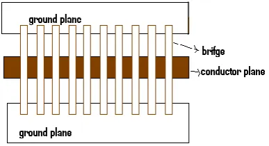
The DMTL phase shifter consists of a high impedance (>50 ) CPW transmission line and MEMS shunt switches that are loaded by the periodic placement of variable capacitance. The configuration of the MEMS shunt switch over the CPW transmission line is shown in Fig. 1. W is the center conductor width, G is the gap width, g0 the bridge height, S the periodic spacing of the MEMS bridges on the CPW line, w and l are the width and length of the MEMS bridge, respectively.
Fig -1: DMTL phase shifter
2.2 Loss versus impedance
An equivalent circuit of the MEMS bridge over the transmission line is shown in Fig. 2, which consists of variable shunt capacitor, Cb of bridge, the per unit length capacitance,Ct and the inductance, Lt of the unloaded CPW transmission line is given by
0 characteristic impedance of the unloaded transmission line and c is the free space velocity. The characteristic impedance, Zl and phase velocity, vl of the loaded line are given by
The loaded line is designed such that Zl ≈ 50 by choosing an unloaded line impedance of Z0 > 50
The Bragg frequency is the frequency at which the characteristic impedance of the line goes to zero, where entire power reflects back. In the case of the DMTL, the up-state inductance–capacitance (LC) resonant frequency of the MEMS bridges is very high (300–600 conductor and the associated unloaded line impedance, both the phase shift and the loss contributed by the loaded line against center conductor width must be determined. The phase shift of the DMTL is determined by the impedance change, which also determines the reflection coefficient of the phase shifter. The phase shift φ of this slow wave structure can be calculated by
1
lu1
r lu© 2015, IRJET.NET- All Rights Reserved
Page 2108
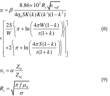
capacitance seen by the DMTL at the up-state is Clu, at thedown-state is Cld and Cr is capacitance ratio. The impedance varies when the loss of the transmission line is changed due to a change in the amount of capacitance on the transmission line. In order to achieve the maximum amount of phase shift for the minimum amount of insertion loss, the attenuation constant α for the unloaded CPW transmission line can be expressed as
2 of multiplicative factor, η0 the characteristic impedance of free space, f the frequency, W the width of the CPW center conductor, G the width of the CPW gap, σ the conductivity of the metal, K the modulus of elliptical integral, k the complementary modulus of k for the elliptical integral, K(k) and K(k ) are the complete elliptic integral of the first kind of modulus k , respectively.
Another important factor which required careful loss per unit length on silicon substrate is higher than that on quartz substrate.It is also important to select the input and output port feed lines to match the dimensions and minimize the radiation loss in these lines.
.
2.3 Design of CPW transmission line
Six types of CPW transmission lines are designed with different impedances on high resistivity quartz substrate. Six types of CPW transmission line are shown in figure 2.In general, these CPW transmission lines differ in terms of their impedances. In each of the design there are 10 shunt capacitance switches, equally spaced and placed above a 30 mm transmission line. The simulated comparison results of the various phase shifters which are designed using advanced design system (ADS) system software are shown in table 1. From this, we can infer that as the characteristic impedance changes there is a change in phase shift and more superior performance than the conventional RF MEMS phase shifter in terms of low insertion loss of −2 dB and high return loss of −12 dB.
a) Bowtie structure
© 2015, IRJET.NET- All Rights Reserved
Page 2109
c) Step structured)Ground Step structure
e)Tapered structure
f) Ground tapered structure
figure 2: structures of transmission lines
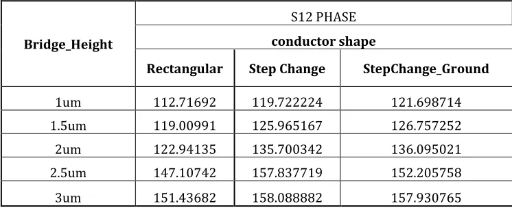
Bridge_Height
S12 PHASE conductor shape
Rectangular Step Change StepChange_Ground
1um 112.71692 119.722224 121.698714
1.5um 119.00991 125.965167 126.757252
2um 122.94135 135.700342 136.095021
2.5um 147.10742 157.837719 152.205758
3um 151.43682 158.088882 157.930765
© 2015, IRJET.NET- All Rights Reserved
Page 2110
3
SIMULATION RESULT
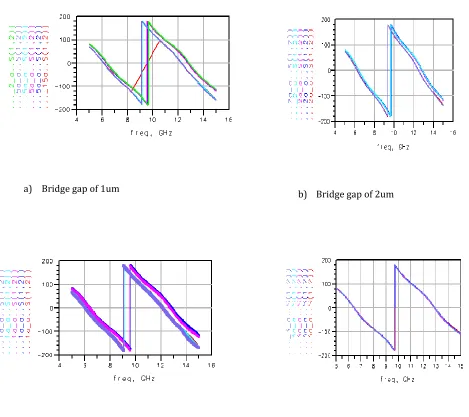
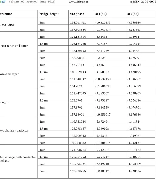
The simulated results of the various phase shifters which are designed using advanced design system (ADS) software are shown in table 2. From this, we can infer that, as the structure changes , the characteristic impedance also changes, and hence there is a change in phase shift
and more superior performance than the conventional RF MEMS phase shifter in terms of low insertion loss of −2 dB and high return loss of −12 dB at ku band frequencies. And also from the result it is clear that the per unit length phase shift is higher than that of the conventional CPW. The graph of the simulated result of different RF MEMS phase shifter using ADS software is shown as follows.
a) Bridge gap of 1um b) Bridge gap of 2um
c)
Bridge gap of 1.5um d) Bridge gap of 3um© 2015, IRJET.NET- All Rights Reserved
Page 2111
structure bridge_height s12 phase s11(dB) s12(dB)
linear_taper 2um 154.063421 -10.822135 -0.558244
3um 157.508884 -11.941934 -0.287863
linear taper_gnd taper
1um 121.131514 -6.54432 -1.08944
1.5um 126.164796 -7.07157 -1.714214
2um 136.130192 -7.861729 -0.944581
3um 156.998811 -12.129 -0.275291
cascaded_taper
1um 147.75713 -9.486 -0.496642
1.5um 148.659143 -9.850302 -0.478495
2um 151.640347 -10.632158 -0.396667
3um 154.7871 -11.586033 -0.316079
bow_tie
1um 151.947095 -9.363707 -0.508205
1.5um 152.5761 -9.395337 -0.624034
2um 157.3702 -9.864559 -0.474701
3um 157.28001 -10.050017 -0.176686
step change_conductor
1um 119.722224 -5.672494 -1.411544
1.5um 125.965167 -6.299098 -1.167476
2um 135.700342 -6.663151 -1.009067
3um 158.088882 -11.886014 -0.292134
step change_both conductor and gnd
1um 121.698714 -6.242167 -1.911422
1.5um 126.757252 -6.754217 -1.030961
2um 136.095021 -7.639718 -0.863089
3um 157.930765 -12.484179 -0.228606
© 2015, IRJET.NET- All Rights Reserved
Page 2112
IV CONCLUSION
In this paper, the RF MEMS phase shifter based on capacitance shunt switch is designed and simulated. We improve the distributed MEMS phase shifter design by using multi-structured configuration of conductor to enable multiple phase shifts in a single RF MEMS structure. With these techniques, we could achieve higher resolutions, larger per unit length phase shift and lower loss phase shifters with smaller device sizes. They remain linear in maintaining return loss (S11≤−12 dB) up to Ku band . The driving voltage reduces the height of the switches, thereby increases the capacitive loading and decreases the phase velocity. As a result, the advantages of the DMTL phase shifters in Ku band are lower insertion loss, higher phase shift and easier integration into RF circuit and systems for different military and commercial applications.
V REFERENCES
[1] R Pierre, G Tayeb, B Gralak, S Enoch. “Quasi-TEM modes in rectangular waveguides: a study based on the properties of PMC and hard surfaces” hal-00319510, version 1 - 8 Sep 2008
[2] Balaji Lakshminarayanan and Thomas M Weller, “ Design and Modeling of 4-bit Slow-Wave MEMS Phase Shifters”, IEEE transactions on microwave theory and techniques, vol. 54, no. 1, january 2006.
[3] Christos G Christodoulou. “RF - MEMS and its Applications to Microwave Systems, Antennas and Wireless Communications” IEEE 2003.
[4] Tzung-Fang Huang, Shih-Wen Lu and Powen Hsu; “Analysis and Design of Coplanar Waveguide-Fed Slot Antenna Array” IEEE Transactions of antenna and Wave propagation,vol.47,no.10,oct-1999.
[5] Gian Guido Gentili and Andrea Melloni ; “The Incremental Inductance Rule in Quasi-TEM Coupled Transmission techniques . Vol.43.no.6,june1995.
[6] Harald Klingbeil and Wolfgang Heinrich; “Calculation of CPW A.C.Resistance and inductance using a Quasi-static Mode-Matching Approach”. IEEE transactions on microwave theory and techniques, vol. 42, no.6, june1994.
[7] Wolfgang Heinrich. “Quasi-TEM Description of MMIC Coplanar Lines Including Conductor-loss Effects” IEEE transactions on microwave theory and techniques, vol.41, no.1, jan.1993.
[8] Thermpon Ativanichayaphong, Ying Cai and J.C. Chiao. “Design and Modeling of Distributed RF MEMS Phase Shifters” VII International Conference on Micro Electro Mechanical Systems, Sept. 21-22, 2005
[9] W. Palei, A.Q. Liu, A.B. Yu, A. Alphones, Y.H. Lee, “Optimization of design and fabrication for micromachined true time delay (TTD) phase shifters” sensors and actuators A119(2005),science direct.
BIOGRAPHIES
Sugesh M S : He is working at Dpt. of ECE in SIMAT as Asst Professor. Specialization in Communication Systems Engineering. His current research interests include the
design, development and
characterization of RF MEMS components. He has published more than 3 research papers in national and international conferences.
B.Nataraj is an Associate Professor in Electronics and Communication
Engineering Department. He
completed his Ph.D in Information and Communication Engineering from Anna University, Chennai. His research interest includes RF /
Microwave and RF MEMS
Devices.He has published more than 10 research papers in national and international journals and 6 papers
in national/international
conferences. He has chaired