CSEIT184604 | Published – 08 May 2018 | May-June 2018 [ (4 ) 6 : 12-16 ]
National Conference on Engineering Innovations and Solutions (NCEIS – 2018)
International Journal of Scientific Research in Computer Science, Engineering and Information Technology © 2018 IJSRCSEIT | Volume 4 | Issue 6 | ISSN : 2456-3307
12
Detection of Object Using Rangefinder
Ms Juslin F,Mr Sudhanva N,Mr Varun B K, Mr Guru Prasad U
Asst.Prof, Department of ECE,ATMECE,Mysore, Students of ECE, ATMECE, Mysore,Karnataka, India
ABSTRACT
A rangefinder is a device that measures the separation from target to the observer, for the reasons of surveying, finding the focus in photography, or precisely pointing a weapon, it makes basic radar utilizing the ultrasonic sensor. This radar works by measuring a range from 3cm to 40 cm as non-contact distance, with angle range between 15˚ and 165˚ .The development of the sensor is controlled by utilizing a little servo motor. Data got from the sensor will be utilized by "processing Development Environment" software to delineate the outcome on a PC screen.
Keywords: Processing Software, Servo motor, Ultrasonic Sensor.
I.
INTRODUCTION
Radar is an object identification framework that uses electromagnetic waves to recognize run, height, heading, or speed of both moving and settled protests, for example, flying machine, ships, vehicles, climate developments, and landscape. When we utilize ultrasonic waves rather than electromagnetic waves, we call it ultrasonic radar. The fundamental parts in any ultrasonic radar are the ultrasonic Sensors. Ultrasonic sensors chip away at a standard like radar or sonar which assesses traits of an objective by translating the echoes from radio or sound waves separately. Radar's data will show up in various ways. Essential and old radar station utilized sound alert or LED, present day radar utilizes LCD show to demonstrate nitty gritty data of the focused on question. We utilize Computer screen to demonstrate the data (separation and edge).
II.
LITERATURE SURVEY
Vladimir I. Koshelev[1]. Titled “Detection and recognition of radar objects at sounding by high-power ultrawide band pulses”ultrawideband (UWB)
estimate signal distortions that affect the noise immunity of multi-position radar.
Taehwan Kim; Sungho Kim; Eunryung Lee; Miryong Park[3].Titled “ Comparative analysis of RADAR-IR sensor fusion methods for objectdetection”.The Radar and IR sensor fusion method for objection detection. The infrared camera parameter calibration with Levenberg-Marquardt (LM) optimization method is proposed based on the Radar ranging data represented by Cartesian coordinate compared with 6 fusion methods. The proposed method firstly performs the estimation of the intrinsic parameter matrix of infrared camera with some optical trick. Then the method searches the extrinsic parameters using the generative approach. The initial angle and translation of the extrinsic parameters are optimized by the LM method with the geometrical cost function. In the experiments, the performance of proposed method outperforms by a maximum 13 times the performance of the other baseline methods on the averaged Euclidian distance error. In future work, the angular noise of the Radar information will be improved and the proposed method will provide the effective proposals for the deep neural network.
III.
DESIGN METHODOLOGY
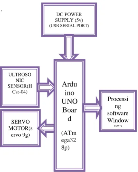
The piece outline of short range radar framework is as appeared in Figure 1 Using IO trigger for no less than 10us abnormal state flag, The Module naturally sends eight 40 kHz and identify whether there is a heartbeat motion back.
On the off chance that the flag back, through abnormal state, time of high yield IO term is the time from sending ultrasonic to returning.
.
Figure 1. Block Diagram of short range Radar Framework
3.1 Arduino UNO Board
Arduino is an equipment and programming organization, undertaking, and client group that plans and fabricates PC open-source equipment, open-source programming, and microcontroller-based packs for building computerized gadgets and intuitive articles that can detect and control physical gadgets. The task depends on microcontroller board outlines. The board gives sets of advanced and simple Input/Output (I/O) sticks that would interface be able to different Expansion sheets (named shields) and different circuits.
Figure 2. Arduino UNO board ULTROSO
NIC SENSOR(H
Csr-04)
0)
DC POWER SUPPLY (5v) (USB SERIAL PORT)
SERVO MOTOR(s
ervo 9g)
Processi ng software Window
(PC)
Ardu
ino
UNO
Boar
d
The sheets highlight serial correspondence interfaces, including Universal Serial Bus (USB) on UNO show, for stacking programs from individual computers.For programming the microcontrollers, the Arduino venture gives a coordinated improvement condition (IDE) makes it simple to compose code and transfer it to the board. It keeps running on Windows, Mac OS X, and Linux. The earth is composed in Java and in view of Processing and other open-source programming. This product can be utilized with any Arduino board. Arduinouno is as shown in the Figure 2. The Arduino Uno has 14 computerized input/yield pins (of which 6 can be utilized as PWM yields), 6 simple data sources, a 16 MHz precious stone oscillator, a USB association, a power jack, an ICSP header, and a reset catch.
3.2 Ultrasonic Sensors
Ultrasonic going module HC - SR04 gives 2cm - 400cm non-contact estimation work, the going exactness can reach to 3mm. The modules incorporate ultrasonic transmitters, collector, and control circuit, inside estimating point 15 degrees Product highlights: Ultrasonic going module HC - SR04 gives 2cm - 400cm non-contact estimation work, the going exactness can reach to 3mm.
The modules incorporates ultrasonic transmitters, beneficiary and control circuit. The fundamental guideline of work. Using IO trigger for no less than 10us abnormal state flag, The Module consequently sends eight 40 kHz and distinguish whether there is a heartbeat flag back. IF the flag back, through abnormal state , time of high yield IO term is the time from sending ultrasonic to returning. Total distance = (high level time×velocity of sound (340M/S)/2. Working principle of ultrasonic sensor is as shown in the Figure 3.
Figure 3. working of ultrasonic sensor
Wire connecting direct as following: 1. 5V Supply
2. Trigger Pulse Input 3. Echo Pulse Output 4. 0V Ground
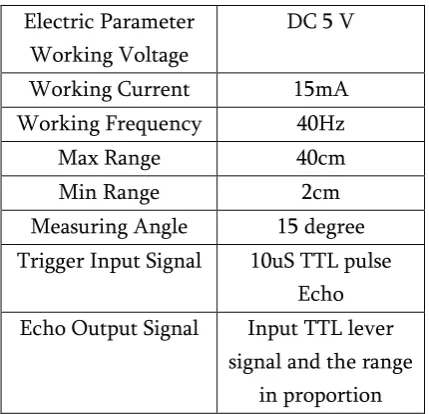
Table 1. Specifications of ultrasonic sensors Electric Parameter
Working Voltage
DC 5 V
Working Current 15mA
Working Frequency 40Hz
Max Range 40cm
Min Range 2cm
Measuring Angle 15 degree Trigger Input Signal 10uS TTL pulse
Echo Echo Output Signal Input TTL lever
signal and the range in proportion
3.3 Servo Motor
Small and lightweight with high yield control. The servo can turn Approximately 180 degrees (90 toward every path), and works simply like the standard sorts yet littler you can utilize any servo code, equipment or library to control these servos.
Specifications: 1. Weight: 9 g
2. Dimension: 22.2 x 11.8 x 31 mm approx. 3. Stall torque: 1.8 kgf·cm
4. Operating speed: 0.1 s/60 degree 5. Operating voltage: 4.8 V (~5V) 6. Dead band width: 10 µs
7. Temperature range: 0 ºC – 55 ºC
3.4 Processing Software
Handling is an open-source PC programming dialect and coordinated advancement condition worked for the electronic expressions, new media workmanship, and visual outline groups with the motivation behind showing non-software engineers the basics of PC programming in a visual setting. The Processing dialect expands on the Java dialect, yet utilizes an improved punctuation and illustrations UI.
Preparing incorporates a sketchbook, an insignificant other option to a coordinated advancement condition (IDE) for sorting out ventures. Each Processing sketch is really a subclass of the PApplet Java class which executes the greater part of the Processing dialect's highlights.
When programming in Processing, every one of extra classes characterized will be dealt with as inward classes when the code is converted into unadulterated Java before ordering. This implies the utilization of static factors and strategies in classes is precluded unless Processing is unequivocally advised to code in unadulterated Java mode.
Preparing additionally takes into consideration clients to make their own particular classes inside the PApplet draw. This takes into account complex information composes that can incorporate any number of contentions and maintains a strategic distance from the confinements of exclusively utilizing standard information writes, for example, int (whole number), singe (character), skim (genuine number), and shading (RGB, RGBA, hex).
3.5 Working Principle
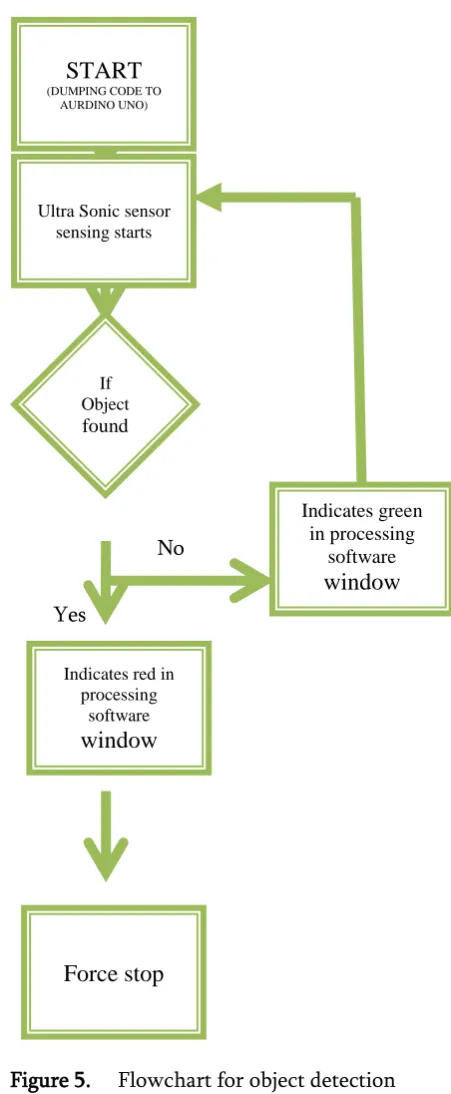
The working principle of object identification is as shown in the flowchartshown below in Figure 5.
No
Yes
Figure 5. Flowchart for object detection
As soon as the code written Embedded C in arduinosoftware is flashed into ArduinoUNO board through USB cable and processing code is run, the short rangefinder starts sensing 1800 to find the object within the range of 40cm. Servomotors are controlled by sending an electrical pulse of variable
START
(DUMPING CODE TO AURDINO UNO)
Ultra Sonic sensor sensing starts
Indicates green in processing
software
window
Force stop
Indicates red inprocessing software
window
If Object
the control wire. When any object is found then it is indicated as red on the processing development window. The green area in the processing window indicates it’s a free area with no objects or obstacles present. The sensing continues unless it is forced stop through the code.
IV.
RESULT
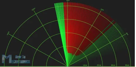
The resulting graphical window of processing software is shown in Figure 4. The red area in the graphical window indicates the object identified up to the range of 40cm with angle coverage of 1800.
The green area indicates that no object being detected in the range of 40cm.
Figure 4. Graphical representation of object identification on Processing Software window
V.
CONCLUSION
Radar is normally used to determine velocity, range, and position of an object. In this project, the distance and angles of detected objects in order to convert these data into visual information. The performance of project is so good. It works smoothly to detect objects within the designed range. The screen shows the information clearly with enough delay for the user to read it. This project could be helpful for object avoidance/ detection applications. This project could easily be extended and could be used in any systems may need it.
VI.REFERENCES
[1] Detection and recognition of radar objects at sounding by high-power ultrawideband
pulsesVladimir I. Koshelev2007 IEEE International Conference on Ultra-Wideband [2] Influence of the ionosphere and the troposphere
on the propagation of radio waves in the detection of space debris objects using multi-position radar systemA. I. Baskakov; A. A. Komarov; M. S. Mikhailov; V. A. Permyakov2017 Progress in Electromagnetics Research Symposium - Fall (PIERS - FALL) [3] Comparative analysis of RADAR-IR sensor
fusion methods for objectdetectionTaehwan Kim; Sungho Kim; Eunryung Lee; Miryong Park2017 17th International Conference on Control, Automation and Systems (ICCAS).
AUTHOR'S BIOGRAPHY
I Ms Juslin F Completed M.Tech in 2016 in Digital Electronics and Communication Systems. Currently working as an Assistant Professor in the Department of Electronics and Communication Engineering at ATME college of Engineering at Mysuru.
I Mr Sudhanva N pursuing BE in Electronics and Communication Engineering at ATME college of Engineering at Mysuru
I Mr Varun B K pursuing BE in Electronics and Communication Engineering at ATME college of Engineering at Mysuru