Learning-Based, Automatic 2D-To-3D Image And Video
Conversion
Hattarki Pooja
Department of Computer Science, Appa Institute of Engineering and Technology Gulbarga, Karnataka, India
ABSTRACT
This work is to present a new method based on the radically different approach of learning the 2D-to-3D conversion from examples. It is based on locally estimating the entire depth map of query image directly from a repository of 3D images using a nearest neighbor regression type idea. Among 2D-to-3D conversion methods, those involving human operators have been most successful but also time consuming and costly. Automatic methods that typically make use of a deterministic 3D scene model, have not yet achieved the same level of quality as they often rely on assumptions that are easily violated in practice. Despite a significant growth in the last few years, the availability of 3D content is still dwarfed by that of its 2D counterpart. To close this gap, many 2D-to-3D image and video conversion methods have been proposed. In this paper we adopt the radically different approach of learning the 3D scene structure. We develop a simplified and computationally efficient version of our recent 2D-to-3Dconversion algorithm. A repository of 3D images, either as stereo pairs or image+depth pairs, we find K pairs whose photometric content most closely matches that of a 2D query to be converted. Then, we fuse the K corresponding depth fields and align the fused depth with the 2D query.
Keywords : 2D to 3D images
I.
INTRODUCTION
The availability of 3D-capable hardware today, such as TVs, Blu -Ray players, gaming consoles, and smart phones, is not yet matched by 3D content production. Although constantly growing in numbers, 3D movies are still an exception rather than a rule, and 3D broadcasting (mostly sports) is still minuscule compared to 2D broadcasting. The gap between 3D hardware and 3D content availability is likely to close in the future, but today there exists an urgent need to convert the existing 2D content to 3D. A typical 2D-to-3D conversion process consists of two steps: depth estimation for a given 2D image and depth based rendering of a new image in order to form a stereo pair. While the rendering step is well understood and algorithms exist that produce good quality images, the challenge is in estimating depth
algorithm automatically estimates the depth for a single image (or video). To this effect, methods have been developed that estimate shape from shading, structure from motion or depth from defocus.
II.
LITERATURE SURVEY
2.1 Priority Depth Fusion module
The priority depth fusion module is the most important module in integrating these depth maps. The proposed priority depth fusion algorithm. The three different depth reconstruction modules produce different depth maps. Here we intend to use non-linear weighting for the three kinds of depth maps. A dense disparity estimation algorithm is used in the motion parallax based depth reconstruction module. The produced depth map of dense disparity estimation is depicted as Cp(_p). Since we are only using the dense disparity estimation for motion parallax based depth reconstruction, we can know
DMP(_p) = Cp(_p). We use two algorithms in the image based depth reconstruction module here, one is color segmentation, which is denoted by Ct(_p), and the other one is motion segmentation,10 which is denoted by Cm(_p). The result of the image-based depth reconstruction is shown as DI (_p) =
Ct(_p) · Cm(_p). The consciousness-based depth reconstruction utilizes the depth from geometry algorithm.
2.2 Defocus using a single image
Depth-from-defocus algorithms based on two or more images are introduced. The reason for using more images is to eliminate the ambiguity in blur radius estimation when the focal setting of the camera is unknown. The images, with which this group of algorithms works, are required to be taken from a fixed camera position and object position but using different focal settings. However, only a small number of 2D video materials satisfy this condition. For example, the focus settings are changed when it is necessary to redirect the audience’s attention from foreground to background or vice verse. To make
defocus as a depth cue suitable for conventional video contents, where we do not have control of the focal settings of the camera, Wong and Ernst have proposed a blur estimation technique using a single image based on the second derivative of a Gaussian filter. When filtering an edge of blur radiusσ with a second derivative of a Gaussian filter of certain variance s , the response has a positive and a negative peak. Denote the distance between the peaks as d , which can be measured directly from the filtered image. The blur radius is computed according to the formula 2 2 2 2 σ = ( d ) − s.
2.3 Linear perspective
Linear perspective refers to the fact that parallel lines, such as railroad tracks, appear to converge with distance, eventually reaching a vanishing point at the horizon. The more the lines converge, the farther away they appear to be. A recent representative work is the gradient plane assignment approach proposed by Battiato, Curti et al... Their method performs well for single images containing sufficient objects of a rigid and geometric appearance. First, edge detection is employed to locate the predominant lines in the image. Then, the intersection points of these lines are determined. The intersection with the most intersection points in the neighborhood is considered to be the vanishing point.
2.4 Atmosphere scattering
depth perception in psychology, little literature can be found in the
field of computer vision on the matter directly converting the atmosphere scattering to depth information directly.
2.5 Patterned texture
Patterned texture offers a good 3D impression because of the two key ingredients: the distortion of individual texels and the rate of change of texel distortion across the texture region. The latter is also known as texture gradient. The shape reconstruction exploits distortions such as perspective distortion, which makes texels far from the camera appear smaller, and/or foreshortening distortion, which makes texels that are not parallel to the image plane shorter the shape-from-texture algorithms focus on the determination of textured surface’s orientations in terms of surface normals. It is also worth noting that a lot of reallife images contain differently textured texture regions or textured areas surrounded by non-textured ones. These different textured regions need to be segmented before most shape-from-texture algorithms can be applied. This group of methods, which require texture segmentation, belongs to the feature-based approach. In more recent years, there has been a shift toward Shape-from-Texture methods that utilize spectral information and avoids prior feature detection.
III.
PROPOSED METHOD
There are two types of 2D-to-3D image conversion methods: semi-automatic methods, that require human operator intervention, and automatic methods, that require no such help.
A. Semi-automatic methods
To date, this has been the more successful approach to 2D-to-3D conversion. In fact, methods that require a significant operator intervention in the conversion process, such as delineating objects in individual frames, placing them at suitable depths,
and correcting errors after final rendering, have been successfully used commercially by such companies as Imax Corp., Digital Domain Productions Inc. (formerly In-Three Inc.), etc. Many films have been converted to 3D using this approach. In order to reduce operator involvement in the process and, therefore, lower the cost while speeding up the conversion, research effort has recently focused on the most labor-intensive steps of the manual involvement, namely spatial depth assignment.
B. Automatic methods
The problem of depth estimation from a single 2D image, which is the main step in 2D-to-3D conversion, can be formulated in various ways, for example as a shape-from shading problem. However, this problem is severely under-constrained; quality depth estimates can be found only for special cases. Other methods, often called multi view stereo, attempt to recover depth by estimating scene geometry from multiple images not taken simultaneously. For example, a moving camera permits structure-from motion estimation while a fixed camera with varying focal length permits depth-from-defocus estimation. Both are examples of the use of multiple images of the same scene captured at different times or under different exposure conditions (e.g., all images of the Statue of Liberty).
IV.
DETAILED DESIGN
component. Each subsection of this section refers to or contains a details description of a system software component. The Algorithm has the following operations on JPEG2000 images:
4.1 Structure Chart
Structured flow chart gives overall strategy for structuring program. It gives details about each module evolve during detailed design of coding and decoding. This chart is a top-down modular design tool, constructed of squares representing the different modules in the system, and lines that connect them. The lines represent the connection and ownership between activities and sub activities as they are used in organization charts.In structured analysis structure charts are used to specify the high-level design or architecture, of a computer program. As a design tool, they aid the programmer in dividing and conquering a large software problem that is recursively breaking a problem down into parts that are small enough to be understood by a human brain. The process is called top-down design or function decomposition. In the design stage, the chart is drawn and used as a way for the client and the various software designers to communicate. During the actual building of the program (implementation), the chart is continually referred to as the master-plan. A structure chart depicts:
The size and complexity of the system. Number of readily identifiable function and
modules within each function.
Find whether each identifiable function is a manageable entity or should be broken down into smaller components.
4.2 Functional Description of the Modules
This section provides the complete description of all the modules use as part of this project.
Introduction: The availability of 3D-capable hardware today, such as TVs, Blu -Ray players, gaming consoles, and smart phones, is not yet matched by 3D content production. Although
constantly growing in numbers, 3D movies are still an exception rather than a rule, and 3D broadcasting (mostly sports) is still minuscule compared to 2D broadcasting. The gap between 3D hardware and 3D content availability is likely to close in the future, but today there exists an urgent need to convert the existing 2D content to 3D.
Design is one of the most important phases of software development. The design is a creative process in which a system organization is established that will satisfy the functional and non-functional system requirements. Large Systems are always decomposed into sub-systems that provide some related set of services. The output of the design process is a description of the Software architecture.
4.3 Design Considerations
The purpose of the design is to plan the solution of the problem specified by the requirements document. This phase is the first step in moving from problem to the solution domain. The design of the system is perhaps the most critical factor affecting the quality of the software and has a major impact on the later phases, particularly testing and maintenance. System design describes all the major data structure, file format, output as well as major modules in the system and their Specification is decided.
4.4 Development Methods
The development method used in this software design is the modular/functional development method. In this, the system is broken into different modules, with a certain amount of dependency among them.
Search for representative depth fields Depth fusion
Depth smoothing Stereo rendering
4.5 Architecture Strategies
It involves identifying the major components of the system and communications between these components. The initial design process of identifying these sub-systems and establishing a framework for sub-system control and communication is called architecture design and the output of this design process is a description of the software architecture.
4.6 System Architecture
The system architecture of the system is as shown below the procedure is as follows The availability of 3D-capable hardware today, such as TVs, Blu -Ray players, gaming consoles, and smart phones, is not yet matched by 3D content production. Although constantly growing in numbers, 3D movies are still an exception rather than a rule, and 3D broadcasting (mostly sports) is still minuscule compared to 2D broadcasting. The gap between 3D hardware and 3D content availability is likely to close in the future, but today there exists an urgent need to convert the existing 2D content to 3D. A typical 2D-to-3D conversion process consists of two steps: depth estimation for a given 2D image and depth based rendering of a new image in order to form a stereo pair. While the rendering step is well understood and algorithms exist that produce good quality images, the challenge is in estimating depth from a single image (video). Therefore, throughout this paper the focus is on depth recovery and not on depth-based rendering, although we will briefly discuss our approach to this problem later. There are two basic approaches to 2D-to-3D conversion: one that requires a human operator’s intervention and one that does not. In the former case, the so-called semiautomatic methods have been proposed where a skilled operator assigns depth to various parts of an image or video.
4.7 2D-to-3D conversion based on global nearest-neighbor depth learning
The approach we propose here is built upon a key observation and an assumption. The key observation is that among millions of 3D images available on-line,
there likely exist many whose 3D content matches that of a 2D input (query) we wish to convert to 3D. We are also making an assumption that two images that are photometrically similar also have similar 3D structure (depth). This is not unreasonable since photometric properties are often correlated with 3D content (depth, disparity). For example, edges in a depth map almost always coincide with photometric edges.
Given a monocular query image Q, assumed to be the left image of a stereopair that we wish to compute, we rely in the above observation and assumption to “learn” the entire depth from a repository of 3D images I and render a stereopair in the following steps:
1) search for representative depth fields: find k 3D images in the repository I that have most similar depth to the query image, for example by performing a k nearest-neighbor (kNN) search using a metric based on photometric properties,
2) depth fusion: combine the k representative depth fields, for example, by means of median filtering across depth fields,
3) depth smoothing: process the fused depth field to remove spurious variations, while preserving depth discontinuities, for example, by means of cross-bilateral filtering,
Figure 1. Block diagram of the overall algorithm.
4.8 KNN search
There exist two types of images in a large 3D image repository: those that are relevant for determining depth in a 2D query image, and those that are irrelevant. Images that are not photometrically similar to the 2D query need to be rejected because they are not useful for estimating depth (as per our assumption). Note that although we might miss some depth-relevant images, we are effectively limiting the number of irrelevant images that could potentially be more harmful to the 2D-to-3D conversion process. The selection of a smaller subset of images provides the added practical benefit of computational tractability when the size of the repository is very large.
One method for selecting a useful subset of depth relevant images from a large repository is to select only the k images that are closest to the query where closeness is measured by some distance function capturing global image properties such as color, texture, edges, etc. As this distance function, we use the Euclidean norm of the difference between histograms of oriented gradients (HOGs) [3] computed from two images. Each HOG consists of 144 real values (4×4 blocks with 9 gradient direction bins) that can be efficiently computed.
Figure 2. shows search results for two outdoor query images performed on the Make3D dataset.
Although none of the four kNNs perfectly matches the corresponding 2D query, the general underlying depth is somewhat related to that expected in the query.
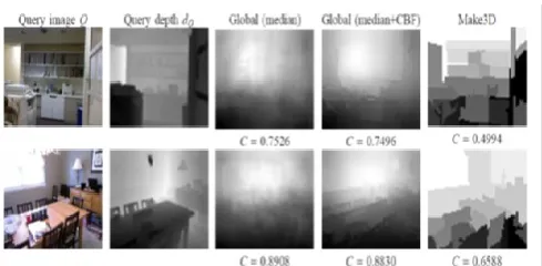
Figure 3. shows the Query images and depth fields
The query, estimated depth by the global method after median-based fusion and after the same fusion and CBF, and depth computed using the Make3D algorithm. Normalized depth cross-covariances are included under each estimated depth field.
V.
CONCLUSION
and with rapid growing computing power in the cloud the proposed algorithm seems a promising alternative to operator assisted 2D to 3D conversion.
VI.
REFERENCES
[1]. L. Angot, W.-J. Huang, and K.-C. Liu, "A 2D to 3D video and image conversion technique based on a bilateral filter," Proc. SPIE, vol. 7526, p. 75260D, Feb. 2010.
[2]. T. Brox, A. Bruhn, N. Papenberg, and J. Weickert, "High accuracy optical flow estimation based on a theory for warping," in Proc. Eur. Conf. Comput. Vis., 2004, pp. 25–36. [3]. N. Dalal and B. Triggs, "Histograms of oriented gradients for human detection," in Proc. IEEE Conf. Comput. Vis. Pattern Recognit., Jun. 2005, pp. 886–893.
[4]. F. Durand and J. Dorsey, "Fast bilateral filtering for the display of high-dynamic-range images," ACM Trans. Graph., vol. 21, pp. 257–266, Jul. 2002.
[5]. M. Grundmann, V. Kwatra, and I. Essa, "Auto-directed video stabilization with robust L1 optimal camera paths," in Proc. IEEE Conf. Comput. Vis. Pattern Recognit., Jun. 2011, pp. 225–232.
[6]. M. Guttmann, L. Wolf, and D. Cohen-Or, "Semi-automatic stereo extraction from video footage," in Proc. IEEE Int. Conf. Comput. Vis., Oct. 2009, pp. 136–142.
[7]. K. Karsch, C. Liu, and S. B. Kang, "Depth extraction from video using non-parametric sampling," in Proc. Eur. Conf. Comput. Vis., 2012, pp. 775–788.
[8]. J. Konrad, G. Brown, M. Wang, P. Ishwar, C. Wu, and D. Mukherjee, "Automatic 2D-to-3D image conversion using 3D examples from the Internet," Proc. SPIE, vol. 8288, p. 82880F, Jan. 2012.
[9]. Lai-Man Po, Xu yuan Xu,Yuesheng
Zhu,Shihang Zhang,Kwok-Wai Cheung and Chi-Wang Ting ICPS 2011 paper "Automatic
2D to 3D Video Conversion Technique based depth from motion and color Segmentation",