IJEDR1404074
International Journal of Engineering Development and Research (www.ijedr.org)3850
RFID and Fingerprint Recognition based Electronic
Voting System for Real Time Application
1
Ashok Nalluri,
2B. Bhanu Teja,
3A.Balakrishna
1M.Tech (Embedded Systems), 2Assistant Professor, 3 M.Tech (Embedded Systems). 1 Department of ECE, SRM University, Chennai, India
2
Department of ECE, Chilkur Balaji Institute of Technology, Telangana, India 3
Department of ECE, Nalanda Institute of Engineering & Technology, Andhra Pradesh, India
________________________________________________________________________________________________________
Abstract - This paper focuses on sophisticated voting system using RFID and Finger print technologies. Each user is provided a voter’s ID in the form of RFID Tag. The hardware design has a Finger print scanning sensor which is used to compare the finger print of the user with the pre-stored finger print of the user. During voting, both the finger prints are checked for matching and if it does not match, then an alert is given using buzzer. Keypad is used for selecting the voting preferences. LCD is used to display the corresponding data for each key to the user. Thus, illegal voting cannot be done since finger print is unique for each person. The voting process is carried out only if the finger print matches with the stored value.
Index Terms - RFID, E-voting, LCD, Fingerprint
________________________________________________________________________________________________________
I.INTRODUCTION
Electronic voting (also known as E-voting) is voting using electronic systems to aid casting and counting votes. Electronic voting technology can include punched cards, optical scan voting systems and specialized voting kiosks (including self-contained direct-recording electronic voting systems, or DRE). It can also involve transmission of ballots and votes via telephones, private computer networks, or the Internet.
In general, two main types of E-voting can be identified
e-voting which is physically supervised by representatives of governmental or independent electoral authorities (e.g. electronic voting machines located at polling stations);
remote E-voting where voting is performed within the voter's sole influence, and is not physically supervised by representatives of governmental authorities (e.g. voting from one's personal computer, mobile phone, television via the internet (also called I-voting).
Electronic voting technology can speed the counting of ballots and can provide improved accessibility for disabled voters. Electronic voting machine has now days become an effective tool for voting. It ensures flawless voting and thus has become more widespread. It ensures people about their vote being secured. It avoids any kind of malpractice and invalid votes. Also such kind of system becomes more economical as consequent expenditure incurred on manpower is saved. It is also convenient on the part of voter, as he has to just press one key whichever belongs to his candidates.
Voting machines use a two-piece system with a balloting unit presenting the voter with a button for each choice connected by a cable to an electronic ballot box.
An EVM consists of two units:
Control Unit
Balloting Unit
The two units are joined by a five-meter cable. The Control Unit is with the Presiding Officer or a Polling Officer and the Balloting Unit is placed inside the voting compartment. Instead of issuing a ballot paper, the Polling Officer in-charge of the Control Unit will press the Ballot Button. This will enable the voter to cast his vote by pressing the blue button on the Balloting Unit against the candidate and symbol of his choice. The controller used in EVMs has its operating program etched permanently in silicon at the time of manufacturing by the manufacturer. No one can change the program once the controller is manufactured.
The main drawback of this system is that, voter’s id checking process is manual hence possibilities of illegal voting by a wrong candidate. And also, possibility of multiple votes by same person.
II.SYSTEM ANALYSIS AND RELATED WORK
This project is very used to improve the security performance in the voting machine. In this project RFID is used as vote ID card. Now day’s some person makes the duplicate vote ID card. But in this project human finger print is used for caste the vote. So this project improves the security performance and avoid forgery vote because naturally one human finger print is different from other human.
A. LPC2129
IJEDR1404074
International Journal of Engineering Development and Research (www.ijedr.org)3851
C.LCD display and SwitchesSwitches function as inputs that give command to the controller what to do and LCD display as output that directs the users how to use the module and also to display the final results. The firmware programmed in LPC2129 is designed to communicate with finger print and operates according the commands received from the switches. Therefore, after receiving the data from finger print and processing and validating, it takes the data from switches and comparing with the data base and updating the data base and display the command and display the result with respect to the switch operations. The switches are used to activate the controller for registration during enrollment, for comparisons to the database while identifying the user, for selecting the party while casting the vote, finally for display of results. LCD screen functions as interface between the user and microcontroller, which displays messages that facilitates the user to know when to register and when to vote, and also whether their vote is valid are not.
It displays “welcome” messages initially and “enrolling” message during enrollment, “identifying” message when controller is comparing the data base whether the user is valid are not, if valid displays “please vote” message, if not displays “no access” message, and finally displays the result with party name with their respective number of votes.
The working of our E-voting system explained in three modes
Enrolling mode
Identification and vote casting mode
Results mode
When the power of Ballot unit is turned on, the ballot unit awaits a “READY SIGNAL” from controller. After getting “READY SIGNAL”, ballot unit displays its “welcome to EVM” message on LCD indicating that the machine is ready and waits for user input. The mode of operation depends on command given by the user from the switches.
D.Enrolling mode
If enrolling mode command is given, the controller waits for input and activates the scanner to accept the finger print, displaying “Enrolling…”on the LCD display. The candidate’s finger print is scanned and generates a unique characters code. During the character code generation, “GENRATING CHARACTER CODE…” is displayed on LCD. This unique code is stored in the EEPROM memory of the controller for the future reference. After all enrollments the system is ready for vote cast.
E.Identification and vote casting mode
Before casting the vote, the candidate has to check for validity. So after user press the identify button the controller displays “identifying ...“message. During this mode the fingerprint of the candidate casting the vote is compared with the finger prints already enrolled in the memory. If it is matched a message “PLEASE VOTE……” will be displayed on LCD. Once the voter presses the button corresponding to the candidate of her/his choice, a four-bit code is generated and sent to the control unit. Once the casting is over message is displayed to whom they voted for.”No ACCESS...” message will be displayed if the same user tries to cast again. The machine returns to the identifying mode and starts all over again for next voting.
F.Results mode
IJEDR1404074
International Journal of Engineering Development and Research (www.ijedr.org)3853
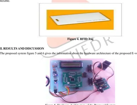
Figure 3. RFID ReaderThe RFID tag is used for providing the bus route information which is arranged in bus. In this project VLF RFID tag is used up to 125 kHz RF range. These tags come with a unique 32-bit ID and are not programmable. Card is blank, smooth, and mildly flexible.
Figure 4. RFID Tag
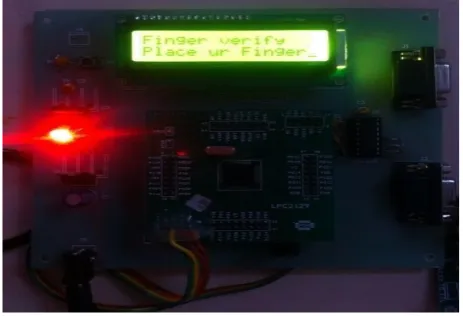
III.RESULTS AND DISCUSSION
The proposed system figure 5 and 6 gives the information about the hardware architecture of the proposed E-voting system
IJEDR1404074
International Journal of Engineering Development and Research (www.ijedr.org)3854
Figure 6. Fingerprint VerificationIV.CONCLUSION
The fingerprint recognition technique that can provide the security to the voting process. Thus if an unauthenticated person tries to cast the vote, the buzzer alert the presiding officer immediately.
REFERENCES
[1] Tai-Pang Wu,, Sai-Kit, Yeung,JiayaJia, Chi-Keung Tang, AndGe´ Rard Medioni “Closed-Form Solution To Tensor Voting: Theory And Applications Transactions On Pattern Analysis And Machine Intelligence”, Vol. 34, No. 8, August 2012.