Receivers and CQI Measures for MIMO-CDMA
Systems in Frequency-Selective Channels
Jianzhong (Charlie) Zhang
Nokia Research Center, 6000 Connection Drive, Irving, TX 75039, USA Email:charlie.zhang@nokia.com
Balaji Raghothaman
Nokia Research Center, 6000 Connection Drive, Irving, TX 75039, USA Email:balaji.raghothaman@nokia.com
Yan Wang
Nokia Research Center, 6000 Connection Drive, Irving, TX 75039, USA Email:yan.2.wang@nokia.com
Giridhar Mandyam
Nokia Research Center, 6000 Connection Drive, Irving, TX 75039, USA Email:giridhar.mandyam@nokia.com
Received 1 March 2004; Revised 9 November 2004
We investigate receiver designs and CQI (channel quality indicator) measures for the jointly encoded (JE) and separately encoded (SE) types of MIMO transmission. For the JE transmission, we develop a per-Walsh code joint detection structure consisting of a front-end linear filter followed by joint symbol detection among all the streams. We derive a class of filters that maximize the so-called constrained mutual information, and show that the conventional LMMSE and MVDR equalizers belong to this class. This constrained mutual information also provides us with a CQI measure describing the MIMO link quality, similar to the notion of generalized SNR. Such a measure is essential for both link adaptation and also to provide a means of link-to-system mapping. For the case of SE transmission, we extend the successive decoding algorithm of per-antenna rate control (PARC) to multipath channels, and show that in this case successive decoding achieves the constrained mutual information. Meanwhile, similar to the case of JE schemes, we also derive proper CQI measures for the SE schemes.
Keywords and phrases:CDMA, MIMO, PARC, CQI, link-to-system mapping, constrained optimization.
1. INTRODUCTION
Information-theoretic studies in [4,5] showed that multiple-transmit, multiple-receive-antenna MIMO systems offer po-tential for realizing high spectral efficiency in a wireless communications system. In [6,7], a practical MIMO con-figuration, a Bell Labs layered space-time (BLAST) system, is deployed to realize this high spectral efficiency for a narrowband TDMA system. MIMO schemes are also be-ing considered for standardization in WCDMA/HSDPA, and may be considered for CDMA2000 as well in the near future. From the point of view of packet transmission with forward error-correction coding, MIMO schemes can be classified into two categories, namely, jointly encoded (JE) and sepa-rately encoded (SE). In a JE scheme, a single encoded packet is transmitted over multiple spatial streams, whereas in SE
each spatial stream consists of a separately encoded packet. Coded-VBLAST and its variants [8], as well as space-time codes [9], fall under the JE category, while schemes such as per-antenna rate control (PARC) and its variants belong to the SE category [2,10,11].
Spreading Scrambling
Information bits
Channel coding
& modulation
Spreading Scrambling
. . .
1 H0,. . .,HL 1 +
. . .
y1
n
Detection decoding
Receiver
yn +
n
Multipath MIMO channel
N
M
Transmitter
Figure1: MIMO-CDMA system illustrated.
proposed in [18]. The study of advanced receivers also leads us to a better characterization of the MIMO-CDMA link. Such characterization of a wireless link, usually known as channel quality indicator (CQI), is very important from the overall system evaluation perspective, both in terms of link adaptation and link-to-system mapping [19]. In SISO sys-tems, the CQI of a wireless link is usually reported to the base station (BS) in the form of the instantaneous SNR seen at the mobile station (MS). At the BS, the scheduler performs the link adaptation by comparing this CQI with some preset threshold to determine the proper modulation and coding scheme (MCS) for this MS. The CQI is also used in gener-ating the so-called short-term frame error rate (FER) ver-sus SNR curves, which provides a simple abstraction of the link for the purpose of system-level simulations. In SISO sys-tems, the mappings of CQI to both MCS and FER, denoted as MCS(CQI) and FER(CQI), are single-dimensional map-pings. For MIMO systems, if an SE MIMO scheme is used, the CQI of each coded stream can still be represented by a single SNR and hence, the single-dimensional mapping of both MCS(CQI) and FER(CQI), just as in the SISO case. However, for JE MIMO schemes, various portions of a packet see different SNRs, and hence the mapping is potentially a complicated multidimensional problem.
In this paper, we first derive a single CQI measure for the JE systems in frequency-selective channels, in order to avoid the complications of multidimensional mappings. The CQI proposed here is based on a so-called per-Walsh code joint detection structure consisting of a front-end linear fil-ter followed by joint symbol detection among all the streams. We derive a class of filters that maximizes the so-called con-strained mutual information, and show that the conventional LMMSE and MVDR equalizers belong to this class. Similar to the notion of generalized SNR (GSNR) [1], this constrained mutual information provides us with a CQI measure describ-ing the MIMO link quality. Such a CQI measure is essential in providing a simple one-dimensional mapping for both link adaption and generating short-term curves for the purpose of link-to-system mapping for JE schemes. For the case of SE transmission, on the other hand, we extend the successive decoding algorithm of PARC [2,3] to multipath channels, and show that in this case successive decoding achieves the
Spreading
S1
a1,m
a2,m
S2 . . .
+
Scrambling
C
Antennam dm
aK,m SK
Figure2: Transmit signal at antennam.
constrained mutual information mentioned earlier. We also derive the link quality measures for the SE transmission sim-ilar to those for JE transmission. We use these measures in simulations with link adaptation.
The rest of the paper is organized as follows.Section 2 presents the MIMO signal model and notation, followed by the treatment of JE MIMO schemes in Section 3 and SE PARC-type schemes inSection 4. Finally, the simulation re-sults are presented inSection 5.
2. MIMO SIGNAL MODEL FOR CDMA DOWNLINK
Consider an M-transmit-antenna, N-receive-antenna MIMO CDMA system as illustrated in Figure 1. After channel coding (which can be either jointly encoded over antennas, or separately for different antennas), the modu-lated symbol streams are demultiplexed before transmission. We denote the number of active users in the system as U
and the number of Walsh codes assigned to these users as K1,. . .,KU, whereK
U
u=1Ku is the total number of active Walsh codes. Without loss of generality, we assume throughout this paper that the first user is the user of interest. As shown in Figure 2, the signal model at themth transmit antenna is given as follows:
dm(i)=c(i) K
k=1
j
whereGis the spreading gain of the system,1andi,j,m, and k are chip, symbol, transmit antenna, and spreading code indices. Note that by definition, j = i/G, where· de-notes ceiling operation. The base station scrambling code is denoted byc(i). Meanwhile,αk stands for the signal ampli-tude associated with spreading codek(we assume for sim-plicity that for a given Walsh code k, the amplitudes are the same for all antennas, extension to MIMO systems with uneven powers across antennas is possible), ak,m(j) is the
jth symbol transmitted at antennamon Walsh codek, and
sk =[sk(1),. . .,sk(G)]T is thekth Walsh code. Note that in this model we have implicitly assumed that the same set of Walsh codes is used across all the transmit antennas.
The transmitted signals propagate through the MIMO multipath fading channel denoted by H0,. . .,HL, where each matrix is of dimensionN∆×M, where∆is an integer that denotes number of samples per chip. The signal model at the receive antennas are thus given by the following equa-tion, after stacking up the received samples across all the re-ceive antennas for theith chip interval:
yi= L
l=0
Hldi−l+ni. (2)
Note thatyi=[yiT,1,. . .,yiT,N]Tis of lengthN∆, and each small vectoryi,nincludes all the temporal samples within theith chip interval. Meanwhile,Lis the channel memory length,
di−l=[d1(i−l),. . .,dM(i−l)]Tis the transmitted chip vec-tor at timei−l, andniis the ((N∆)×1)-dimensional white Gaussian noise vector withni ∼N(0,σ2IN∆). Note thatσ2 denotes noise variance andIN∆is the identity matrix of size
N∆×N∆. Furthermore, in order to facilitate the discussion
on the linear filters at the receiver, we stack up a block of 2F+ 1 small received vectors (note that the notation of 2F+ 1 suggests that we are assuming the filters to be “centered” with
Ftaps on both the causal and anticausal side):
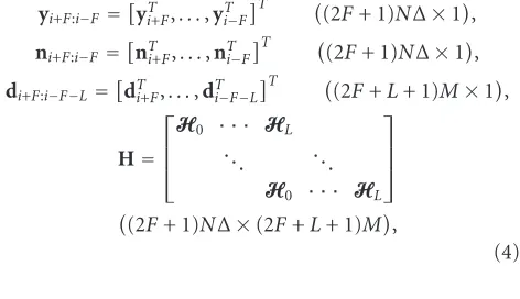
yi+F:i−F=Hdi+F:i−F−L+ni+F:i−F, (3)
where 2F+ 1 is the length of the LMMSE equalizing filter and
yi+F:i−F=
yT
i+F,. . .,yiT−F
T
(2F+ 1)N∆×1,
ni+F:i−F=
nTi+F,. . .,nTi−F
T
(2F+ 1)N∆×1,
di+F:i−F−L=
dTi+F,. . .,dTi−F−L
T
(2F+L+ 1)M×1,
H=
H0 · · · HL . .. . ..
H0 · · · HL
(2F+ 1)N∆×(2F+L+ 1)M,
(4)
1Although practical systems such as 1xEV-DV use different spreading gains for data and voice traffics, we assume a fixed spreading gain in this paper for simplicity of notation.
where the dimensions of the matrices are given next to them. Note that to keep the notation more intuitive, we keep the subscripts at a “block” level. For instance,yi+F:i−Fis the vec-tor that contains blocksyi+F,. . .,yi−F, where each block is a vector of sizeN∆×1. The transmitted chip vectordi+F:i−F−L is assumed to be zero-mean, white random vectors whose covariance matrix is given by Rdd = σ2
dbI2F+L+1. We
fur-ther define some more notation for future use. We define
d¯i=di+F:i−F−L\di, wheredi+F:i−F−L\didenotes the submatrix ofdi+F:i−F−Lthat includes all the elements ofdi+F:i−F−Lexcept those indi. With this definition, we rewrite the signal model (3) as
yi+F:i−F=Hdi+F:i−F−L+ni+F:i−F =H0di+H¯0di¯+ni+F:i+F,
(5)
H0 is the submatrix inH that is associated with the
sub-vector di and H¯0 = H\H0. Furthermore, we define the
covariance matrix of the received signal yi+F:i−F as R
E[yi+F:i−FyHi+F:i−F]=σd2HHH+σ2Iand a related matrixR R−σ2
dH0HH0 =σd2H¯0HH¯0 +σ2I.
3. RECEIVERS AND CQI MEASURES FOR JE SCHEMES
In this section, we first propose a suboptimal yet computa-tionally feasible receiver structure, the per-Walsh code joint spatial detection structure consisting of a front-end linear filter followed by joint detection across all spatial streams. We derive a class of filters that maximize the so-called con-strained mutual information and show that this mutual in-formation can act as a single CQI that characterizes the JE MIMO link.
Before we discuss the per-Walsh code joint detection structure, we note that at the first glance one may be tempted to use the instantaneous mutual information of the channel
I(di+F:i−F−L;yi+F:i−F) as the CQI of interest. While it is indeed a single quantity that fully characterizes the MIMO link at the moment, in a frequency-selective channel, the optimal decoding needed to achieve this mutual information requires a joint sequence detection algorithm known as vector Viterbi algorithm (VVA) [20]. Unfortunately, the VVA has a compu-tational complexity that is exponential with both the number of transmit antennasMand number of Walsh codesK, which becomes prohibitively high asMorKgrows. Therefore, the channel mutual information by itself is not a good CQI mea-sure since its associated receiver cannot be implemented in a realistic system.
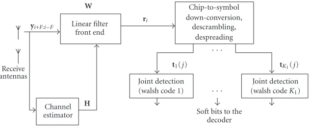
To avoid these complexity issues, in this paper, we fo-cus on a class of suboptimal receivers with the so-called per-Walsh code joint detection structure, as illustrated in Figure 3. In this structure, a front-end linear filter bankW(of size (2F+ 1)N∆×M) converts the multipath MIMO channel into an effective single-path MIMO channel in some optimal fashion. That is,
Receive antennas
yi+F:i−F
W
Linear filter front end
ri
Chip-to-symbol down-conversion,
descrambling, despreading
· · ·
· · ·
Channel estimator
H
Joint detection (walsh code 1)
t1(j)
Soft bits to the decoder
Joint detection (walsh codeK1)
tK1(j)
Figure3: Block diagram of per-Walsh code joint detection.
where theM×M matrixWHH
0 denotes the effective
post-filtering single-tap MIMO channel, n WHH¯0d¯ i + WHn
i+F:i−F ∼ N(0,WHRW) is the M×1 postfiltering in-terference plus noise.
Our idea is to use the so-calledconstrained mutual infor-mationI(di;ri(W)) as the single CQI that characterizes the MIMO link. Let us verify if this is a valid choice, that is, if there is a computationally feasible receiver associated with this choice of CQI. To this end, we note that since ri(W) sees an effective single-path MIMO channel, the orthogonal-ity of the Walsh codes allow us to separate symbols carried on different Walsh codes, and joint detection is only needed along the spatial dimension for each Walsh code, as shown in Figure 3. Therefore, the per-Walsh code joint detection struc-ture is computationally feasible and I(di;ri(W)) is a valid choice of CQI to describe this MIMO link.
SinceI(di;ri(W)) is dependent on the filterW, one would naturally want to design the filter W such that the con-strained mutual information I(di;ri(W)) is maximized. In the following sections, we turn our attention to the prob-lem of optimizing the filter W, and show that this solu-tion coincides with the LMMSE or MVDR solusolu-tions. Be-fore we proceed, we complete the description of the sig-nal models in Figure 3. Recall that c(i) is the scrambling code and that j = i/G is the symbol index, we define
C(j)=diag{ c(jG),. . .,c(jG+G−1)}as the diagonal matrix that denotes the scrambling operation for thejth symbol in-terval. With this nomenclature, we arrive at the output sig-nals of the composite operations of chip-to-symbol down-conversion, descrambling, and despreading on the collection of chip vectors{rjG,. . .,rjG+G−1}:
tk(j)=rjG,. . .,rjG+G−1
CH(j)s k
=αkWHH0ak(j) +n, k=1,. . .,K1,
(7)
where ak(j)=[ ak,1(j),. . .,ak,M(j)]T is the transmitted sym-bol vector carried on thekth Walsh code for thejth symbol interval and n ∼ N(0, (1/G)WHRW). Note that in (7) we have implicitly used the facts that (a) the Walsh codes are or-thonormal, that is,sTk1sk2 =δk1,k2; (b) the scrambling code
is pseudorandom, that is,E[c(i1)c∗(i2)]=δi1,i2, whereE[·]
denotes expectation operation and (·)∗ denotes conjugate
operation.
3.1. Optimizing W by mutual information maximization
We proceed to obtain the filter W that maximizes
I(di;ri(W)). In order to obtain a closed-form solution, we as-sumedito be Gaussian and therefore we are really maximiz-ing the (Gaussian) upper bound of this mutual information. Note that it is well understood that the MMSE receiver is mu-tual information maximizing in a more general context [21] and we provide the proof for the particular MIMO-CDMA system of interest for completeness.
Theorem 1. Assumingdito be Gaussian, the conditional mu-tual informationI(di;ri(W)|H)is maximized by (MCstands for maximum capacity)WMC =R−1H0Afor anyM×M
in-vertible matrixA.
For the proof, seeAppendix A.
3.1.1. Connection to the LMMSE or MVDR chip MIMO equalizers
The idea of transforming a multipath channel to a single-path channel is better known as chip-level equalization of CDMA downlink, mostly using LMMSE or MVDR algo-rithms. Defining an error vector of z = di −WHyi+F:i−F and an error covariance matrixRzz = E[zzH], the MIMO LMMSE chip-level equalizerWis the solution of the follow-ing problem:
WLMMSE=arg min W Trace
Rzz
=arg min
W E
di−WHy
i+F:i−F2,
(8)
whose optimal solution is given by WLMMSE = σd2R−1H0.
Defining di,LMMSE = WHLMMSEyi+F:i−F as the estimated chip vector, it is easy to see that this estimate is biased, since
can be obtained by solving instead the MIMO MVDR prob-lem:
WMVDR=arg min W Trace
WHRW, s.t.WHH
0=IM, (9) whose solution isWMVDR=R−1H0(HH0R
−1
H0)−1. Note that
one can show that the MVDR solution is a special case of the so-called FIR MIMO channel-shortening filter [1]. We pro-ceed to show in the following corollary that both LMMSE and MVDR solutions are actually mutual information maxi-mizing. This result shows that one cannot do better than the simple LMMSE or MVDR filter, as long as these filters are followed by joint detection in the spatial dimension.
Corollary 1. Both the LMMSE and MVDR equalizer solu-tions,WLMMSEandWMVDR, are mutual information
maximiz-ing.
For the proof, seeAppendix B.
3.2. Two alternative CQI measures for JE MIMO
From the discussion above, it is clear that we can use
I(di;yi+F:i−F) as the single CQI to describe the MIMO link. However, the constrained mutual informationI(di;yi+F:i−F) is obtained with the assumption that modulation and cod-ing are applied directly on the chip signals di. Since a real-istic CDMA systems the modulation and coding are always applied on symbol signals ak(j), we should instead use the symbol-level mutual informationI(ak(j);tk(j)) as the CQI of the link. To this end, note that once the front-end filter
WMC =R−1H0Ais fixed in Figure3, it is straightforward to
show that
Iak(j);tk(j)
=logIM+βkσd2HH0R
−1
H0, (10)
and consequently the single-dimensional mappings are de-fined as MCS(I(ak(j);tk(j))) and FER(I(ak(j);tk(j))), where
βk=α2kGis a scalar factor that translates the chip-level SNR (SNR of di) to the symbol-level SNR (SNR oftk(j)). Note that here we have implicitly assumed thatα1 = · · · =αK1, which is a reasonable assumption for most practical situa-tions.
Alternatively, we may also use another symbol-level CQI based on the so-called generalized SNR (GSNR) [1]:
GSNRk=βk
Traceσd2IM
TraceRzz
WMVDR
, (11)
where Rzz is defined above (8). With this definition of GSNR, the single-dimensional mappings are defined as MCS(GSNR) and FER(GSNR).
Remark1. The difference between chip and symbol mutual information suggests that we may combine the filter blockW
and the following block (down-conversion, etc.) inFigure 3 into a composite filter block, and then directly optimize this composite filter. However, a closer examination shows that doing so increases the complexity significantly without re-vealing much additional insightabout the problem. The chip
versus symbol mutual information discussion is analogous to the chip versus symbol-level equalization problem discussed in [15].
4. RECEIVERS AND CQIS FOR PARC-TYPE SE SCHEMES
We now turn our attention to PARC-type SE schemes. In this section, we extend the successive decoding algorithm of PARC [2,3] to multipath channels, and show that in this case successive decoding achieve the constrained mutual informa-tion meninforma-tioned earlier. We also derive the link quality mea-sures for the SE transmission similar to those for JE trans-mission.
4.1. Successive decoding in the presence of multipath
In [3], a capacity achieving successive decoding procedure is developed for a memoryless GMAC (Gaussian multiple-access channel). Here we follow the treatment in [3] and derive the successive decoding procedure in the presence of multipath, and show that in this case the successive decoding achieves the constrained mutual information I(di;yi+F:i−F) we discussed inSection 3.1. Again, in the information anal-ysis we assume that modulation and coding are directly ap-plied on the chip signals for ease of exposition. We will show in a later subsection the changes and additions necessary for a realistic CDMA system where successive decoding and can-cellation occur at symbol level.
We start by rewriting the signal model of (5) asyi+F:i−F= H0di+ni, whereni ∼N(0,R), to stress that successive de-coding is intended for the elements ofdi=[di,1,. . .,di,M]T. To this end, let there be a successive decoding algorithm that decodesdi,1→di,m→di,Min that order. At each stagem, as-suming that all the previous symbolsdi,1,. . .,di,m−1are
cor-rectly decoded, a decision variableui,mis generated as a linear combination of the outputyiand the previously decoded sig-nals:
ui,m=fmHyi+F:i−F− m−1
l=1 bm∗,ldi,l
=fH
mH0di+fmHni− m−1
l=1 b∗m,ldi,l
(12)
for 1 < m ≤Mand 1 ≤l≤m−1. Note here eachfmis a (2F+ 1)N∆×1 vector known as feedforward vector and each
b∗m,1is a scalar feedback coefficient (the conjugate operation
∗is here only for notational convenience when we move to vector-matrix representation). At each stagem, we intend to maximize the mutual informationI(ui,m;di,m) by optimizing
Cm= max
fm,bm,1,...,bm,m−1I
ui,m;di,m
, (13)
where Cm denotes the maximum mutual information ob-tained at each stage. To solve (13), we first rewrite (12) as
ui,m=fmHh0,mdi,m+fmH
H0,(m)di,(m)+ni
+fH
mH0,[m]−bHm,[m]
di,[m],
where [m]={1,. . .,m − 1} and (m)={ m + 1,. . .,M} are the indices before and after m within the set {1,. . .,M}, respectively. Accordingly, partitions of H0 and di are defined as H0 = [H0,[m],h0,m,H0,(m)] and di = [dTi,[m],di,m,dTi,(m)]T. Finally, the vector bm,[m] is defined
as bm,[m] = [bm,1,. . .,bm,m−1]T. Defining the
signal-to-interference-plus-noise ratio (SINR) of the (14) as
γm(fm,bm,[m]), we have
γm
fm,bm,[m]
= σ
2
dfmHh0,mhH0,mfm fH
mR(m)fm+σd2fmHH0,[m]−bHm,[m] 2, (15)
whereR(m)=σd2H0,(m)HH0,(m)+σ2R. Similar to [3, Theorem 1],
we argue that sinceI(ui,m;di,m)=log(1 +γm(fm,bm,[m])), the
maximum mutual informationCm is achieved by maximiz-ing the SINR in (15). However, after the obvious step of set-tingfH
mH0,[m]−bHm,[m]=0, the remainder ofγm(fm,bm,[m]) is
a generalized eigenproblem [22] whose solution is given by
fmopt =νmR(−m1)h0,mfor anyνm>0. Therefore, the solution of (13) is
Cm= max
fm,bm−1,...,b1
Iui,m;di,m
=log1 +σ2
dhH0,mR−(m1)h0,m
.
(16) DenotingC=I(di;yi+F:i−F) as the constrained mutual in-formation discussed in Section 3.1, all what we are left to do is to show that C = M
m=1Cm. However, from (16), one can verify that Cm = I(di,m;yi+F:i−F|di,[m]) and use
the chain rule of mutual information [23]I(di;yi+F:i−F) =
M
m=1I(di,m;yi+F:i−F|di,[m]) to arrive atC =
M
m=1Cm. What we have shown is that for MIMO-CDMA systems in a frequency-selective channel, if the transmitter can somehow have the feedback knowledge of the maximum mutual in-formationCmfor antennamand assign a transmission rate of Rm = Cm on that antenna, we can design a successive decoding scheme similar to those in the memoryless chan-nel [2, 3], to achieve the constrained mutual information
C =I(di;yi+F:i−F). Before we proceed, we rewrite (12) in a more compact form:
ui=FHyi+F:i−F−BHdi, (17) whereui=[ui,1,. . .,ui,M]T,F=[ f1,. . .,fM], and
BH=
0 . . . 0
b2,1∗ 0 ...
..
. . .. . ..
b∗M,1 . . . b∗M,M−1 0
, (18)
and we denote the optimal solution ofFandBasFSDand BSD.
4.1.1. Connection betweenFSDandWMC
In this subsection, we show how the optimal feedforward fil-ter FSDrelates to the WMC we designed for joint detection
a little earlier in Section 3.1. To this end, we note that in-stead of performing successive decoding directly on the re-ceived signalyi+F:i−F, we can first passyi+F:i−FthroughWMC
to getri(WMC), on which we then perform successive
decod-ing. Similar to (17), we define the decision vector in this case as:
ui=FHr i
WMC
−BHd
i, (19) and find the optimal F and B (which we denote as FSD
andBSD) by maximizingCm=maxF,BI(ui,m;di,m) form= 1,. . .,M. From the derivation inSection 4.1, it is easy to see that C=I(ri(WMC);di) = I(yi+F:i−F;di) =
M
m=1Cm (note the second equality comes fromTheorem 1), meaning that successive decoding after the filter WMC achieves the same
constrained mutual information as direct successive decod-ing. In fact, we can further show in the following proposition thatCm=CmandFSD=WMCFSDfor certain situations. The
proof is straightforward and is omitted here.
Proposition 1. Cm =Cm. Furthermore, if the two sets of fil-ters,(FSD,BSD)and(FSD,BSD), are chosen such that the
deci-sion vectorsuiandui are both unbiased2, that is,E[u
i|di]=
E[ui|di]=di, thenFSD=WMCFSD. 4.1.2. Connection to the constrained
MIMO LMMSE equalizer
InSection 3.1.1, we showed the connection between the mu-tual information maximizing filter WMC and the
conven-tional MIMO chip equalizers WLMMSE andWMVDR. In this
section, we show that similar connection can be made be-tween the successive decoding filter pair (FSD,BSD) and the
so-called constrained MIMO LMMSE equalizer presented in [24] for a more general EDGE MIMO system where the feedback channel includes more than one effective tap. On the contrary, the constrained LMMSE equalizer for a CDMA MIMO system has only one feedback channel tap and can be viewed as a special case of [24]. The constrained LMMSE for MIMO CDMA is given by the following optimization prob-lem with a structural constraint requiringBH=BH+I
Mto be lower triangular with unit diagonals:
FCL,BCL=arg min F,B
TraceRzz
=arg min
F,B E FHy
i+F:i−F−BHdi2,
s.t.BH=BH+IM=
1 . . . 0
b∗2,1 1 ...
..
. . .. . ..
bM∗,1 . . . b∗M,M−1 1 , (20)
where the error vector is defined asz= BHd
i−FHyi+F:i−F. We show in the following proposition that the constrained LMMSE solution is indeed the same as the successive decod-ing solution with unbiased output.
Receive antennas
yi+F:i−F Feedforward filter
F
ri
Chip-to-symbol down-conversion,
descrambling, despreading
{ak,m(j)}
α1B Feedback
filter
v1(j)
−
· · ·
· · ·
. . .
Demod decode
vM(j)
−
Demod decode Figure4: Illustration of successive decoding at symbol level.
Proposition 2. If the successive decoding filter pair(FSD,BSD)
is chosen such that the decision vectorui is unbiased, that is,
E[ui|di]=di, thenFSD=FCLandBSD=BCL−IM. Proof. See [24] for details about the solution of (20).
Remark2. Throughout our discussion, we have used the ar-gument that as long as the rate assigned on antennamis be-low Cm:Rm ≤ Cm, we can provide the correct decision on
di,m to drive the successive decoding process. However, in a practical system many factors (such as Doppler shift, imper-fect feedback, etc), can lead to decision errors ondi,mwhich propagates through the successive decoding process. From a receiver design point of view, the constrained LMMSE prob-lem of (20) can be modified to mitigate the impact of error propagation. However, it is much harder to account for these error propagation effects in the information-theoretical anal-ysis of the successive decoding approach.
4.2. Successive decoding at symbol level
In the discussion of successive decoding above, we have as-sumed that modulation and coding are directly applied on the chip signals di. InFigure 4, we show the changes nec-essary to perform successive decoding at symbol level for a realistic CDMA system. Here we assume α1 = · · · = αK1 for simplicity of notation. In this case, the feedforward filter
Fstill operates on chip signalsyi+F:i−Fwhereas the feedback filterα1B(α1is needed to ensure correct symbol amplitude)
operates on estimated symbol signals{ak,m(j)}instead. Note that unlike Figure 3, the output of the despreading blocks
v1(j),. . .,vM(j) is organized intoM vectors of size K1 ×1
along the spatial dimension.
4.3. CQI measures for PARC-type systems
Since each antenna is separately encoded, the link-to-system mapping for PARC-Type systems is much easier than in the case of joint space-time encoding. Again we have two alterna-tive CQIs for the link-to-system mapping purpose. One can use the symbol SINR given by
γm,k=βkγm=βkσd2hH0,mR−(m1)h0,m (21)
as the CQI to generate the mapping as FER(γm,k) for each antenna m. Recall fromSection 3.2thatβk=α2kGis a scalar factor that translates the chip-level SINR to the symbol-level SINR. Alternatively, one can use the symbol-level mutual in-formation given by
Cm,k=log
1 +βkσd2hH0,mR−(m1)h0,m
(22)
as the CQI to generate the mapping as FER(Cm,k) for each antennam.
5. SIMULATION RESULTS
The algorithms described in this paper are evaluated in a realistic link-level simulator conforming to the CDMA2000 1xEV-DV standard [19,25]. The simulation results are pre-sented in three subsections. In the first subsection, we com-pare the performance results of different receiver algorithms assuming a simple coded VBLAST [8] transmission scheme. In the second subsection, we present some preliminary link throughput results for both coded VBLAST and PARC schemes with link adaptation. Lastly, we show the effective-ness of the two CQI measures discussed inSection 3.2when coded VBLAST scheme is used at the transmitter. Note that although we have focused on the coded VBLAST and PARC schemes in this paper, the algorithms and concepts described here can be extended to other more complicated MIMO transmission schemes.
5.1. Receiver performance comparison
We assume the coded VBLAST [8] scheme at the MIMO transmitter. In the coded VBLAST scheme, the coded frame is simply split across theM transmit antennas after modu-lation, therefore it can also be viewed as a simple form of space-time code. Here we compare three receivers: LMMSE with separate detection, LMMSE with joint detection, and constrained LMMSE as shown in (20) with separate detec-tion. Note that, in this case, successive decoding is not pos-sible since the transmit signals are coded across all anten-nas. Therefore, the symbol estimates {ak,m(j)} in Figure 4 cannot be reconstructed from decoder outputs and should be regenerated successively from the signalsv1(j),. . .,vM(j). Without going into too much detail, we state that there are two approaches for generating these symbol estimates: hard-decision or soft-hard-decision estimates. In the simulation results presented here, we have used conditional mean-based soft es-timates that are similar to those used in [26].
Table1: Simulation parameters. Note that geometry is the ratio of average received power from the serving BS versus average received power from interfering BSs.
Parameter name Parameter value
System CDMA 1xEV-DV
Spreading length 32
Channel profile Vehicular A
Mobile speed 30 km/h
Filter length 16
Number of Tx/Rx antennas 2/2
Modulation format QPSK
Information data rate 312 kbps Turbo code rate 0.6771
Geometry (dB) 6
Number of Walsh codes assigned to
3 the userK1
Total number of active Walsh codes in
25 the systemK
FER
10−3 10−2 10−1 100
Traffic Ec/Ior
−15 −14 −13 −12 −11 −10 −9 −8
LMMSE, separate detection
Constrained LMMSE, separate detection LMMSE, joint detection
Figure5: Comparison of performances for different receivers.
5.2. Link throughput with link adaptation
In order to demonstrate the performance of MIMO schemes with link adaptation, we derive the parameters of each packet transmission from a table consisting of 4 sets of parame-ters, each set being known as amodulation and coding scheme (MCS). This is illustrated inTable 2.
Table 2 is a subset of the 5-level table used in HSDPA [27]. In order to achieve these spectral efficiencies approxi-mately, we use the set of parameters shown inTable 3in the context of the 1X-EVDV packet data channel. Note that we have taken necessary measures to make sure the compari-son is fair in the sense that the throughput results of the two schemes are obtained with the same allocated bandwidth and transmission time.
Table2: Modulation and coding schemes for link adaptation [27].
MCS number Modulation Coding rate Spectral efficiency
1 QPSK 1
4 0.5
2 QPSK 1
2 1.0
3 16-QAM 1
2 2.0
4 16-QAM 3
4 3.0
Table3: 1xEV-DV PDCH parameters for link adaptation (4 Walsh codes assigned).
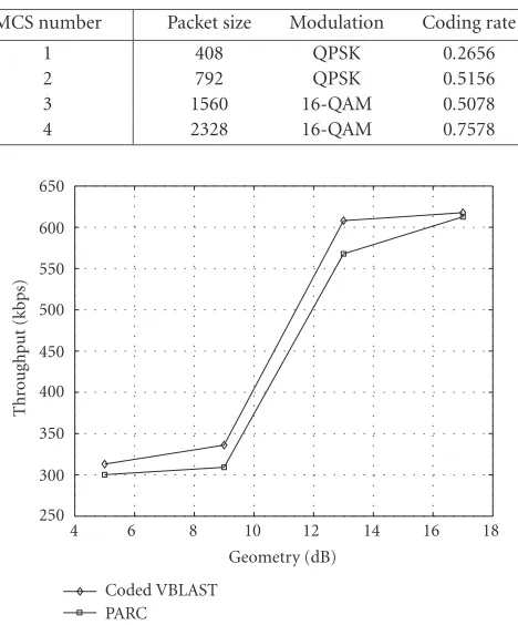
MCS number Packet size Modulation Coding rate
1 408 QPSK 0.2656
2 792 QPSK 0.5156
3 1560 16-QAM 0.5078 4 2328 16-QAM 0.7578
250 300 350 400 450 500 550 600 650
Thr
o
ug
hpu
t
(kbps)
4 6 8 10 12 14 16 18
Geometry (dB) Coded VBLAST
PARC
Figure 6: Throughput comparison between coded VBLAST and PARC. Constrained mutual information is used as CQI for link adaptation.
10−4 10−3 10−2 10−1 100
FER
−12 −11 −10 −9 −8 −7 −6 −5 −4 GSNR (dB)
Figure7: Short-term FER curves with GSNR.
fully utilized in this simulation, where only a small set of MCS schemes is used. More granularity in the link adap-tation might lead to different results. Another advantage of PARC is that the existing HARQ mechanisms in 1xEV-DV are readily applicable in PARC, as shown in [28].
Remark3. In Sections3and4, we have assumed Gaussian modulation in calculating the mutual information-based CQI. However, since 16-QAM or QPSK modulation is used in practice, using the Gaussian mutual information (here we denote asCGau) may portray an overly optimistic picture of
the channel and thus mislead the BS in transmitting at a rate that is above the “true” information rate of the channel un-der the additional constraint of the practical constellation. To see this, we assume a measuredCGau=3.3 bps/Hz at the MS.
According toTable 2, we can support the fourth MCS scheme (MCS4) which has a coding rate of 0.75 and a 16-QAM mod-ulation. However, if we recalculate the mutual information of the channel under the additional constraint of 16-QAM modulation (here we denote asCQAM) [29], it may happen
that CQAM = 2.8 bps/Hz, which means that transmitting
with MCS4 will always result in a packet error and we should be using MCS3 instead.
In the simulation, we have devised two mechanisms to avoid the negative effects of the overly optimistic Gaussian CQI measure.
(i) By simply multiplyingCGauwith a scaling factorα <1,
we can make the CQI estimate a bit more conservative. This scaling can also account for other practical imperfections such as channel estimation error, Doppler, and so forth. Typ-icallyα=0.8 to 0.9.
(ii) Adopt a confirmation process such that after an MCS scheme is selected, the mutual information under the ad-ditional constellation constraint of that particular MCS is recalculated. If this constellation-constrained mutual infor-mation falls below the inforinfor-mation rate prescribed by the current MCS scheme, move one grade up in the MCS table
10−4 10−3 10−2 10−1 100
FER
0 0.5 1 1.5 2 2.5 3
Constrained mutual information
Figure8: Short-term FER curves with constrained mutual infor-mation.
and pick the next MCS scheme with lower information rate. This confirmation process repeats until the first MCS scheme in the table, or until we find an MCS scheme where the constellation-constrained mutual information is greater than the information rate associated with this MCS scheme.
5.3. Short-term FER (CQI) curves
In this section, we use computer simulations to obtain the
FER(CQI) curves as the first step of link-to-system map-ping for the JE coded VBLAST scheme. As mentioned ear-lier, both the GSNR and the constrained mutual information
I(di;yi+F:i−F) measures enable us to characterize the MIMO link by a single CQI, so that a multidimensional mapping can be avoided. In the simulations, we assume the spatial chan-nel model (SCM) specified by [30]. Particularly, the urban macro scenario [30] is implemented. In the SCM model, the channel delay profile itself is a random vector with a different multipath channel profile for each realization. In our simu-lation, we first generate 10 such independent realizations of delay profiles and then generate thousands of channel real-izations for each delay profile.
At the receiver, we use the LMMSE receiver followed by the per-Walsh joint detection algorithm. The parameters of the link are illustrated in Table 1 (except we set Geometry = 0 dB in the simulations presented here). The modula-tion and coding scheme used is MCS1. Figure 7 plots the FER as a function of the instantaneous value of the GSNR, whileFigure 8provides a similar plot with respect to the con-strained mutual information.
with different realizations, the more effective the measure is as an indicator of link quality. Given this criterion, the con-strained mutual information is seen to be more suitable than the GSNR. These are, however, preliminary results requiring further investigation since we have not accounted for other system-level issues such as HARQ in these simulations.
6. CONCLUSION
In this paper, we investigate receiver designs for the jointly encoded (JE) and separately encoded (SE) types of MIMO transmission. For the JE transmission, we develop a per-Walsh code joint detection structure consisting of a front-end linear filter followed by joint symbol detection among all the streams. We derive a class of filters that maximize the so-called constrained mutual information, and show that the conventional LMMSE and MVDR equalizers belong to this class. This constrained mutual information also provides us with a quantity describing the link quality, similar to the no-tion of GSNR. For the case of SE transmission, we extend the successive decoding algorithm of PARC to multipath chan-nels, and show that in this case successive decoding achieves the constrained mutual information. Finally, the algorithms and concepts developed in the paper are evaluated in a real-istic CDMA 1xEV-DV link simulator with and without link adaptation.
APPENDICES
A. PROOF OF THEOREM1
Since diis Gaussian,ri(W) is also Gaussian. One can write out this mutual information as3 I(d
i;ri(W)|H) =
H(ri(W)|H) − H(ri(W)|H,di) = log|WHRW| − log|WHRW| (note |A| denotes the determinant of ma-trixA), and obtain the optimal filterWMCby solving
WMC=arg max W log
WHRW−logWHRW
=arg max
W log
IM+σd2WHH0HH0W
WHRW−1, (A.1)
where IM is the identity matrix of size M ×M. The di-rect optimization of (A.1) is difficult, given that W is a (2F+ 1)N∆×Mmatrix. Here we resort to the data process-ing lemma [23] to provide an upper bound onI(di;ri(W)|H) and then show the bound is achievable. To this end, we note that sinceri(W)=WHyi+F:i−F, di→yi+F:i−F→ri(W) forms a Markov chain, conditioned on the knowledge of the chan-nelH. Therefore, by the data processing lemma, the inequal-ity
Idi;ri(W)|H
≤Idi;yi+F:i−F|H
(A.2)
3H(·|·) denotes conditional entropy. The default base for the logarithm operation is 2 and the information is in bps/Hz.
holds for anyW. From the signal modelyi+F:i−F = H0di+ H¯0d¯i+ni+F:i+F, one can use the identityI(di;yi+F:i−F|H) =
H(yi+F:i−F|H)−H(yi+F:i−F|H,di) to show that
Idi;yi+F:i−F|H
=logI(2F+1)N∆+σd2R
−1
H0HH0
=logIM+σd2HH0R
−1
H0,
(A.3)
where the last equality is a result of the identity log|I+AB| = log|I+BA|[4]. From (A.1) and (A.3), one can verify that this upper bound is achieved by setting WMC = R−1H0A
for any invertible matrix A, that is, I(di;ri(WMC)|H) = I(di;yi+F:i−F|H).
B. PROOF OF COROLLARY1
It is obvious for WMVDR since all we need to do is to set A=(HH0RH0)−1and applyTheorem 1. On the other hand,
with the help of matrix inversion lemma [31] one can rewrite
WLMMSEas
WLMMSE=σd2R−1H0
IM+σd2HH0R
−1
H0 −1
, (B.1)
and then setA = σd2(IM+σd2HH0R
−1
H0)−1 to complete the
proof.
ACKNOWLEDGMENTS
We would like to thank Dr. Dung Doan of Qualcomm for helpful discussions, and Chris Jensen of Nokia Research Cen-ter for proofreading the revised draft. We are also grateful to the anonymous reviewers whose comments greatly improved the presentation of this paper.
REFERENCES
[1] N. Al-Dhahir, “FIR channel-shortening equalizers for MIMO ISI channels,”IEEE Trans. Commun., vol. 49, no. 2, pp. 213– 218, 2001.
[2] S. T. Chung, A. Lozano, and H. Huang, “Approaching eigen-mode BLAST channel capacity using V-BLAST with rate and power feedback,” inProc. IEEE 54th Vehicular Technology Con-ference (VTC ’01), vol. 2, pp. 915–919, Atlantic City, NJ, USA, October 2001.
[3] M. K. Varanasi and T. Guess, “Optimum decision feedback multiuser equalization with successive decoding achieves the total capacity of the Gaussian multiple-access channel,” in
Proc. 31st Asilomar Conference on Signals, Systems, and Com-puters (ACSSC ’97), pp. 1405–1409, Pacific Grove, Calif, USA, November 1997.
[4] E. Telatar, “Capacity of multi-antenna Gaussian channels,”
Bell Labs Technical Journal, June 1995.
[5] P. F. Driessen and G. J. Foschini, “On the capacity formula for multiple input-multiple output wireless channels: a geometric interpretation,”IEEE Trans. Commun., vol. 47, no. 2, pp. 173– 176, 1999.
[7] P. W. Wolniansky, G. J. Foschini, G. D. Golden, and R. A. Valenzuela, “V-BLAST: an architecture for realizing very high data rates over the rich-scattering wireless channels,” inProc. International Symposium on Signals, Systems, and Electron-ics (ISSSE ’98), pp. 295–300, Pisa, Italy, September–October 1998.
[8] X. Li, H. Huang, G. J. Foschini, and R. A. Valenzuela, “Ef-fects of iterative detection and decoding on the performance of BLAST,” inProc. IEEE Global Telecommunications Confer-ence (GLOBECOM ’00), vol. 2, pp. 1061–1066, San Francisco, Calif, USA, November–December 2000.
[9] V. Tarokh, N. Seshadri, and A. R. Calderbank, “Space-time codes for high data rate wireless communications: perfor-mance criterion and code construction,”IEEE Trans. Inform. Theory, vol. 44, no. 2, pp. 744–765, 1998.
[10] Lucent, “Contribution to 3GPP: R1-010879: Increasing mimo throughput with per-antenna rate control,” 2001.
[11] Mitsubishi, “Contribution to 3GPP: R1-040290: Double space time transmit diversity with sub-group rate control (DSTTD-SGRC) for 2 or more receive antennas,” 2004.
[12] A. Klein, “Data detection algorithms specially designed for the downlink of CDMA mobile radio systems,” inIEEE 47th Ve-hicular Technology Conference (VTC ’97), vol. 1, pp. 203–207, Phoenix, Ariz, USA, May 1997.
[13] I. Ghauri and D. T. M. Slock, “Linear receivers for the DS-CDMA downlink exploiting orthogonality of spreading se-quences,” inProc. 32nd Asilomar Conference on Signals, Sys-tems, and Computers, vol. 1, pp. 650–654, Pacific Grove, Calif, USA, November 1998.
[14] S. Werner and J. Lilleberg, “Downlink channel decorrelation in CDMA systems with long codes,” in IEEE 49th Vehicu-lar Technology Conference (VTC ’99), vol. 2, pp. 1614–1617, Houston, Tex, USA, May 1999.
[15] T. P. Krauss, W. J. Hillery, and M. D. Zoltowski, “MMSE equal-ization for forward link in 3G CDMA: symbol-level versus chip-level,” inProc. 10th IEEE workshop on Statistical Signal and Array Processing, pp. 18–22, Pocono Manor, Pa, USA, Au-gust 2000.
[16] M. J. Heikkila, P. Komulainen, and J. Lilleberg, “Interference suppression in CDMA downlink through adaptive channel equalization,” inIEEE 50th Vehicular Technology Conference (VTC ’99), vol. 2, pp. 978–982, Amsterdam, The Netherlands, September 1999.
[17] L. Mailaender, “Low-complexity implementation of CDMA downlink equalization,” inProc. 2nd International Conference on 3G Mobile Communication Technologies, pp. 396–400, Lon-don, UK, March 2001.
[18] H. Nguyen, J. Zhang, and B. Raghothaman, “A kalman-filter approach to equalization of CDMA downlink chan-nels,”EURASIP Journal on Applied Signal Processing, vol. 2005, no. 5, pp. 611–625, 2005.
[19] 3rd Generation Partnership Project 2, “1xEVDV evaluation methodology,” 2001.
[20] W. Van Etten, “Maximum-likelihood receiver for multiple channel transmission systems,”IEEE Trans. Commun., vol. 24, no. 2, pp. 276–283, 1976.
[21] S. Verdu,Multiuser Detection, Cambridge University Press, Cambridge, UK, 1998.
[22] G. H. Golub and C. F. Van Loan,Matrix Computations, The Johns Hopkins University Press, Baltimore, Md, USA, 1991. [23] T. M. Cover and J. A. Thomas,Elements of Information Theory,
Wiley Interscience, New York, NY, USA, 1991.
[24] J. Zhang, A. Sayeed, and B. Van Veen, “Space-time MIMO re-ceiver with constrained optimization,” inIEEE 58th Vehicular
Technology Conference (VTC ’03), vol. 1, pp. 532–536, Or-lando, Fla, USA, October 2003.
[25] 3rd Generation Partnership Project 2, “IS-2000-2-C: Physical Layer Standard for CDMA2000 Spread Spectrum Systems— Release C”.
[26] L. Mailaender and J. G. Proakis, “Linear-aided decision-feedback equalization for the CDMA downlink,” in Proc. 37th Asilomar Conference on Signals, Systems, and Comput-ers, vol. 1, pp. 131–135, Pacific Grove, Calif, USA, November 2003.
[27] 3GPP TSG-RAN, “Contribution r1-040366, draft document for multiple-input multiple output in UTRA”.
[28] H. Zheng, A. Lozano, and M. Haleem, “Multiple ARQ pro-cesses for MIMO systems,” inProc. 13th IEEE Symposium on Personal, Indoor, and Mobile Radio Communications (PIMRC ’02), vol. 3, pp. 1023–1026, Lisbon, Portugal, September 2002.
[29] R. E. Blahut, “Computation of channel capacity and rate-distortion functions,” IEEE Trans. Inform. Theory, vol. 18, no. 4, pp. 460–473, 1972.
[30] 3GPP-3GPP2 SCM AHG, “3SCM-132: Spatial channel model text description,” April 2003.
[31] L. Scharf,Statistical Signal Processing: Detection, Estimation and Time Series Analysis, Addison Wesley, New York, NY, USA, 1990.
Jianzhong (Charlie) Zhang received the B.S. degree in both electrical engineering and applied physics from Tsinghua Univer-sity, Beijing, China, in 1995, the M.S. de-gree in electrical engineering from Clemson University in 1998, and the Ph.D. degree in electrical engineering from the University of Wisconsin at Madison in 2003. He has been with Nokia Research Center, Irving, Texas, since June 2001. His research has focused on
the application of statistical signal processing methods to wireless communication problems. From 2001 to 2004, he worked on the transceiver designs for both EDGE and CDMA2000/WCDMA cel-lular systems. Since July 2004, he has focused on the standardiza-tion of IEEE 802.16e standard, especially in the areas of LDPC codes and limited feedback-based MIMO precoding.
Balaji Raghothamanreceived his B.E. de-gree in electronics and communication en-gineering from Coimbatore Institute of Technology (1994), and his M.S. (1997) and Ph.D. (1999) degrees in electrical en-gineering from The University of Texas at Dallas. During his graduate studies, he spent two summers in the Wireless Products Group, Texas Instruments. Dr. Raghothaman joined Nokia Research
Yan Wangreceived the B.S. degree from the Deptartment of Electronics, Peking Univer-sity, China, in 1996, and the M.S. degree from the School of Telecommunications Engineering, Beijing University of Posts and Telecommunications (BUPT), China, in 1999. From 1999 to 2000, he was a mem-ber of BUPT-Nortel R&D Center, Beijing, China. In 2003, he received his Ph.D. de-gree from the Deptartment of Electrical
En-gineering, Texas A&M University. Since 2003, he has been a Re-search Engineer in Nokia ReRe-search Center, Irving, Texas. His re-search interests are in the area of statistical signal processing and its applications in wireless communication systems.
Giridhar Mandyamis the Director of the Radio Systems Group in the Radio Commu-nications Laboratory, Nokia Research Cen-ter (NRC), and the Head of NRC, San Diego. Born in Dallas, Dr. Mandyam re-ceived the B.S.E.E. degree (magna cum laude) from Southern Methodist University in 1989, the M.S.E.E. degree from the Uni-versity of Southern California in 1993, and the Ph.D. E.E. degree from the University of