®
UNIVAC
HIGH-SPEED PRINTER
DESCRIPTION
AND
THEORY
PX 616
List of Illustrations Lis t of Tables
Introduction •
Glossary and Abbreviations Circuit Symbols
CONI'ENIS
SECTION 1
GENERAL DESCRIPTION
1. 2. 3. 4. 5. 1. 2. General Specifications
Physical Description
a. Uniservo Unit b. Control Unit c. Memory Unit •
d. Printer Uni t
Basic Operation •
a. Univac Code •
b. Operation •
c. Special Functions
d. Error Detection •
Controls and Indicators
a. Supervisory Control
b. Test Control Panel c. Power Control Panel
Power Control Circuits.
Machine Systems
a.
b.
c.
d.
Tape Circuits
Paper Feed System • Input Circui ts. Memory Circuit
Panel
.
SECTION 2
LOGICAL OPERATION
PX 616
CONTENTS (Continued)
e. Code Generator Circuit
.
. . .
·
· · · ·
·
f. Comparator Circuit
.
. .
.
·
·
· ·
·
·
g. Charge Capacitor, and Print and Check Circuit
·
h. Ribbon Feed Control Circuit
· · ·
i. Function Table One Circuit
· · ·
.
.
3. Equipment Operations
4. a. b. c. d. e. f. g. h. i.
Tape Load . . • Initial Start. Read Cycle • . • Print Cycle • •
Read, No Print . • • • •
Print, No Read . • • • • • • . • •
Single Line • • . • • . • • • •
Read Forward, Read Backward (Manual Read) • • • • •
Rewi nd • • • • . • . • . . • • • •
Special Equipment Functions •
a. Zero Suppression
b. MUltiline . • •
c. Computer Digit
d. Fast-Feed.
5. Error-Detection Circuits
a.
b.c.
d. e. f. g. h.Odd-Even Error. • • • • •
Greater, or Less Than, 120 Errors •
Address Line Error • • • •
Paper Feed Error • • • • • . • • • Fas t-Feed Error • • • • • •
Charge Error • • • • • •
Pri nt Error • • • • • • • .
All-Out Error • •
PX 616
Figure 1-1 1-2 1-3 1-4 1-5 1-6 1-7
LIST OF ILWsrRATIONS
SECTION 1
GENERAL DESCRIPfION
Univac High-Speed Printer • Print Head Assembly • • • Typewheel Shaft Assembly Paper Feed Assembly • • • Simplified Block Diagram, HSP Supervisory Control Panel Controls Supervisory Control Panel Indicators
SECTION 2
LOGICAL OPERATION
2-1 Power Control Circuit • • • • • • • • • • • • • • 2-2 Tape Reading Circuits • • • • • • • •
2-3 Paper Feed System • • • • . • • • • •
2-4 Clutch and Brake Energizing Circuit • • • • • • • 2-5 Effect of Tape Skew • • • • • • • • •
2-6 HS Printer Memory Circuits • • • • 2-7 a. Typical Memory Tube Circuit ••
2-7 b. Typical Memory Tube FIring Curve • • • • •
2-8 Code Generator Circuit • • • • • • • • • • • • • • • • • 2-9 Relationship Between Index Typewheel and Code Wheel • 2-10 Pulse Path from G53 to Code Generator •
2-11 Comparator Actuating Circuits • • • • • • • • • •
2-12 Ribbon Feed Control • • • • • • • • • • .
2-13 Function Table One Logic • • • • • • • • • • •
2-14 Tape LO'ad Operation • • • • • • • •
2-14 a. Bad Spot Reading • • • •
2-15 Initial Start and Read • • • • • • •
2-16 Read, No Print • • •
2-17 Print, No Read • • • • •
2-18 Single Line • • • • • • • • • •
2-19 Read Forward, Read Backward 2-20 Rewind • • • • • • • • • •
2-21 Zero Suppression Function. • • • • • • • • •
2-22 Plugboard Suppression Zeros in Character Positions 23 and 24 • • • • • • • • • • • • • • • • • •
2-23 Multiline Relay Connections for Text Example • • • • 2-24 Multiline • • • • • • . • • • • • • • • • •
2-25 Computer Digit - Read Cycle • • • •
2-26 Computer Digit - Print Cycle • • • • •
2-27 Transfer Between Input and Memory • • • • • • • • • • 2-28 Fast-Feed Operation - Delay • • • • • • • • • • • •
PX 616
Page
xxii 5
LIST OF ILLUSTRATIONS (Continued)
Figure
2-29 Fast-Feed Operation - Homepaper • • • 2-30 Fast-Feed Operation - Typical Example • 2-31 Index Line On Backplate • • • • • • . • 2-32 Fast-Feed Operation - FF V Example 2-33 Fast-Feed Operation - Precedence 2-34 Fast-Feed Operation - Overflow Logic
2-35 Fast-Feed Operation - Form Overflow . • • • .
2-36 Check Thyratron Plate Voltage Curve •
A
Complete HS Printer Logical Drawing •PX 616
vi
Page
LIsr OF TABLES
1 Univac Code for the High-Speed Printer • • • •
2 Supervisory Control Panel Control Functions
3 Test Control Panel Control Functions
4 High-Speed Printer Delay Flip-Flops,
5 High-Speed Printer Control Switches
6 High-Speed Printer Relay Functions • • • • • • • •
7 Print Cycle Timing - High-Speed Printer
PX 616
Page
147 148 154
156
1.60
i . INTROOUCT ION
This Manual has been produced as an aid to personnel recelvlng training on the technical aspects of the Remington Rand Univac High-Speed Printer, and as a guide in logical fault-determination. A thorough understanding of the logics involved in the operation of the HS Printer will be of invaluable assistance in determining the area involved in any particular fault.
The Manual should be read in conj unction with the "prograDDller's and
Operator's Manual for the High-Speed Printer" also published by Remington Rand Univac Division of Sperry Rand Corporation, as the text herein makes frequent reference to Operator's or PrograDlller's procedures. A knowledge of these procedures is necessary in order to understand the problems that may be en-countered by these personnel in operating the Printer.
Although the text of the Manual is, for the most part, devoted to logical theory, it bas been necessary at times, due to the very nature of the machine, to explain the operation of a particular area of the equipment by means of electronjc or mechanical theory. For a person who may be unfamiliar with the fundamentals of these fields, such portions of the text have been marked at the beginning and end of the section with a single and double asterisk
respectively. By passing by these portions, such persons will not necessarily be deprived of a knowledge of portions of the equipment which may be beyond their scope.
The Manual does, however, presuppose a knowledge of binary computation on
the part of all readers, and, if this prerequisite is not existent, it is
recommended that any good text on the subject be consulted. Further information respecting the Remington Rand Uniservo, which is mentioned frequently in the text and is an operating adjunct to the HS Printer, may be obtained by referring to Remington Rand publications specifically written for the Uniservo.
In many places throughout the text., specific typographic symbols have been mentioned without enclosing the symbol itself in quotes, as is the usual method of representation. For example, " •... the hammer prints the symbol
%
when the solenoid ii aetuated ... " This apparent omission has beenpurposely applied, inasmuch as including the quotation marks may confuse the reader by implying that the quotation marks themselves are included in the printing operation in the example given, a condition which could quite conceivably occur.
In nearly every instance throughout the text, following the discussion of certain Printer funct"ions, one or more practical examples are given in order
to amplify the explanation. It should not be considered that the examples
quoted are the only possible situations that may occur, the examples being merely representative of such situations. It is considered also that by
detailing these examplei a very thorough idea of the circuit logic may be imbued in tbe reader, this being of considerable value in fault determination.
Figure
A,
at the end of the Manual, which logically represents the wholeHigh-Speed Printer system less power supply, should be referred to constantly in studying the text, together with such individual area drawings that are in-cluded throughout the Manual.
ii. GLOSSARY and ABBREVIATIONS
The terms and expressions used in this Manual are germane to the Univac High-Speed Printer, and do not necessarily reflect the general use of these terms as expressed in other Univac publications or the computer field in general. Wherever possible, if a term or expression has two or more meanings or has equal use throughout the Univac system, all possible alternatives are given.
The use of abbreviations has been kept to a mInImum in this text although in cases where a term, expression or symbol appears in numerous places within a Section or sub-Section, the word is written in full initially, with the abbrevia-tion in parentheses following. Subsequent repetitions of the expression
throughout the remainder of the Section will usually be abbreviated. Adder
Address
Alert
All-Out Detector
Amplifier
Bad Spot
Binary Counter
Block
See Quarter Adder.
Refers to the selection of a particular Memory location. Address line, Address gate are associated terms.
Refers to a preparatory signal, usually on a gate. The final enabling or permissing signal will not be identified as an "alert."
A circuit which notes the condition of all
Check tubes, to insure that each is extinguished when required.
A circuit used to invert and develop a signal of some specifically required amplitude.
An area on Univac magnetic tape ~hat is faulty due to some reason. Holes are punched two and one-half inches prior to the appearance of a bad spot on a tape, and two and one-half inches following a bad spot, and each two and one-half inches throughout the bad spot. A photo-electric cell detects the faulty area and activates the appropriate circuits.
Refers to a bi-stable device that is used for counting. One used alone can count to two; two can count to four; three can count to eight. The Univac code and the majority of counting in
this equipment is based on a binary counting system.
A unit of measure used in the Univac system. A block equals 720 characters, sixty words, or six blockettes.
Blockette
Brake, Paper Feed
Brake, Servo
Breakpoint
Buffer
Capstan
Carriage
CC
CE
Center Drive
Channel
CIF
Character
A unit of measure used in the Univac system. A
blockette equals 120 characters, ten words, or
one-sixth of a block.
A device located on the Paper Feed clutch
assembly and used to stop the rotation of the Paper Feed Tractors.
A device located on the servo clutch assembly
for the purpose of stopping rotation of the capstan.
A
Univac character representing a flexible"stop" signal. It may be observed visually by actuating a switch located on the Supervisory Control Panel.
A device permitting a signal to pass in only
one direction. When several signals are brought together to a common output a buffer will be used to prevent each signal from passing
back along another path. I~ this sense the
buffer acts as an isolating medium.
The device used to move the tape past the Read Head.
A mechanical component used to move the print wheel and ribbon to and from the paper and print head area.
Charge Capacitor
Charge Error.
The drive-shaft assembly controlling the feeding of tape.
1) A term used to designate an area of the magnetic tape on which one particular binary digit of the Univac code is present, e.g., Sprocket Channel.
2) An area of the paper loop used in the
programming of the Printer.
Clear Input Flip-flops.
A Univac unit of measure, composed of seven
binary digits standing for one digit, alphabetic, or special symbol. Twelve characters equal one word, one hundred and twenty equal one blockette.
Clear
Clear Pulse
Clutch, Paper Feed
Clutch, Servo
Code Generator
Code Wheels
Commutator, Paper Feed
Comparator
Computer Digit
Counter, Main
Counter, Ring
CV
To restore a storage or memory device to a pre&cribed state, usually zero.
A signal from the Code Wheel which synchronizes the Code Wheel Generator with the Code Wheel. The device used to couple the paper drive
tractors to the typewheel drive motor. The unit which engages the capstan and the
center drive motor on the Uniservo.
A six-stage binary type counter with six outputs that correspond to the Univac code. The Code Wheel Generator is controlled hy the Code Wheels. Three wheels with polished flat portions. The wheels are used to synchronize the print wheel
to the print head print circuits.
Three commutators having two, three, and six polished flat areas, and used to control paper spacing.
A
device used to compare the output of the Code Wheel Generator with the information stored in the Memory. A signal is produced when the in-formation agrees, which causes a printing action to occur.A special High-Speed Printer function. The Univac code contains certain characters which are considered "non-printable." The characters are usually function symbols or symbols which initiate an operation. The Computer Digit function will recode a non-printable character to a character that may be printed.
A series of seven binary counters used to select Address lines and to count index pulses. A count may be made to a total of one hundred and twenty-eight.
A loop of interconnected bi-stable elements such that one, and only one is in a specified state at any given time, and such that, as input signals are counted, the position of the one specified state moves in an ordered sequence around the loop. In the High-Speed Printer this is a six-stage counter for Multiline operation. Control Voltage.
De-ion
Delay Flop (DF)
Delay Flop, Retriggerable (RDF)
Delay Line
Differentiator (Dif, D)
Digit
Enable
Extinguish, -ed Fast-Feed
Field
Fire, -ed Flip-Flop
Function Table
A signal which alerts the Keyed Bt circuit and provides a Not Reading (NR) signal.
" . . t ' . .
See Clrcult Symbols sectlon of thls manual.
See "Cil"cuit Symbols" section of this manual.
A
device used to delay a signal a definite amount of time. (See SPI , SP2).A device, the output of which is proportional to the derivative of the input signal. Spec., an RC circuit with a time constant equal to one tenth or less of the input signal. The output that is used, leading edge or trailing edge, will be determined by LE or a TE being lettered
within the symbol. (See also "Circuit Symbols" section of this Manual).
A
unit of measure equal tQ one character. One hundred and twenty digits comprise a blockette. As used in this text, a permissing signal whichpermits a pulse (or signal) to pass a gate. Depending upon circumstances a gate may require more than one enable in or~er to pass a signal (be enabled).
Non-conducting, dark, off.
A
machine function used to move the paper a pre-determined distance non-stop. There are six fast-feed circuits on the High-Speed Printer.Zones specified by plugboard connections where it may be desired to suppress zeros to the left of the most significant digit in any numerical portion of a blockette.
Conducting, ignited, on.
A device having two stable states and two inputs. The circuit remains in either s~ate until caused
to change to the other state by application of the corresponding signal.
A circuit designed to accept information coded by one method and convert this information to another code. For example, binary to decimal.
Function Table One The function table used to decode Univac non-printable characters into the particular special function each is required to perform, also known as "Special Symbols Decoder."
Gate A circuit having an output and some or many
inputs so designed that the output is energized when certain input conditions are met. In this Manual the first signal'to a gate is usually referred to as an alerting signal or an alert, and the signal completing the gate requirements is referred to as a final enable.
General Clear (GC) An operating function to clear the machine to a static condition.
Head Amplifiers Components within the Uniservo amplifying the information received from magnetic tape.
Home Paper The machine operation used to correctly position
the printer form in relation to the paper loop.
Hub The receptacle for a plugboard interconnecting
cable assembly. More frequently referred to as a "jack" in this text.
ICD Inhibit Center Drive.
Inhibition, Inhibit A signal, (usually placed on a gate), which prevents an output from occurring. Also known as a "disable."
Integrator, Integrating, Int An RC circuit with a tim~ constant equal to ten times, or greater, than the applied signal.
IS Initial Start signal.
Jam, Jamming A continuing voltage level which prevents other signals from influencing a circuit.
Jam Clear A signal used to clear the Input Flip-Flops.
Keyed B+ A signal from the Memory regulated power-supply
which is used to extinguish the trailing edge of the output of the Memory tube. It is used to "clear" the Memory.
LE Leading Edge.
L Function Table The smaller, eight line output section of the ' Minor Address function table.
L Lines The output lines of the L Section Minor Address function table.
Major Address Function Table The function table used to decode the Minor Address function table outputs in order to select the various address lines.
Memory A part of the equipment composed of 840 Memory
units arranged in 120 groups of seven, in which 120 characters, or one blockette, may be stored. Memory Location A device composed of seven Memory cells in
which one character may be stored.
Memory Unit A bistable electronic unit in which a binary digit of information may be stored.
M Function Table The major section, fifteen line output of the Minor Address function table.
Minor Address Function Table The function table used to change the binary output of the main counter into a code suitable for the Major Address Function Table, in order to select a correct Address line.
MRS Manual Read Start.
MfO Mul tiline Time Out.
Multiline A mach~ne operation that permits one blockette
of information to be printed on from two to six lines.
Mylar Tape
Mylar Drive
NR
Odd-Even Pulse, Signa~ (O.E)
Paper Loop
A special plastic tape used as a buffer between the Read Head and the metal magnetic tape. The Mylar protects the Head from dirt and wear.
A motor unit used to move the Mylar Tape over the Read Head at constant rate.
Not Reading signal.
The odd-even or check pulse has been added to the Univac code for purposes of checking. All
characters must have an odd number of binary digits. This is accomplished by the addition of an odd-even pulse when required.
A punched paper tape loop composed of seven channels and used to control Fast-Feed and Home Paper operations.
PC
PCG
Permissive Plugboard
PM
PM
P-PM PP
Print Actuator
Print Cycle
Printer
Print Hammer
Print Head
Print Location
Print, No Read (PNR)
Print Check.
.
Probe Code Generator. See "Enabl e. "
A unit that permits versatile operation of machine functions by means of a flexible inter-connection system composed of metal-protected cables, similar to a telephone patchboard. Probe Memory Signal. The context or symbolic representation in this Manual will preclude the possibility of this abbreviation being confused with the abbreviation for "Photomultiplier." Photomultiplier tube.
Print, minus Probe Memory. Prevent Print.
A solenoid-operated device that actuates the print hammers. Located on the Print Head, there are 130 of these components.
The opera~ion during which comparison and
printing occurs.
A synonym used throughout the text of this Manual to denote the High-Speed Printer. One of 130 metal hammers that are sharply forced against the Print Wheel by the print actuators. The hammers are located on the Print Head.
This chassis, located on the Printer unit, contains 130 print hammers and 130 print
actuators. The Print Head and the Print Wheel perform the actual printing operation.
The HSP has 130 circuits that control the actuating of 130 print-hammers. Each of these circuits is composed of a Check thyratron and a Print thyratron tube. These circuits are
referred to as Print Locations.
A
Printer operation that permits the repeated printing of information stored in the Memory. New information is not read-in during this operation.PX 616
Print Wheel A series of sixty-five wheels, each containing
two rows of type. Each row of type contains
the fifty-one printable characters. The wheel
rotates at a speed of 750 rpm.
Quarter Adder (QA) A circuit used in the odd-even checking of the
binary digits read from the tape. Two inputs, or no input results in a lack of output,
whereas an input to either side results in an output.
Read Cycle A major machine operation devoted to reading
one blockette from magnetic tape and storing it in the Memory.
Ribbon Feed The unit which holds the ribbon and controls
the rate of travel of the ribbon.
Read Head The device used to read eight channels from the
magnetic tape. Located on the front panel of
the Uniservo.
Read (One-Blockette)Backward A machine operation, manually controlled, that
permits the unit to read on~ blockette of
information backward, then ~top.
Read (Ope-Blockette) Forward A machine operation, manuSlly controlled, that
permits the unit to read one blockette of information forward, then stop.
Read, No Print (RNP) A machine operation, manually-controlled, which
permits the unit to read information without printing.
RS Read Start.
Servo A term used to refer to the Uniservo.
Set Used to denote an electronic function whereby a
bistable device (usually a flip-flop) is placed in a particular state. The opposite condition may be termed "restore."
SCD Start Center Drive.
SP, SP Pulse Sprocket pulse, the eighth channel on the
magnetic tape.
SP l The sprocket pulse, delayed five microseconds.
SP2 The sprocket pulse delayed 7.5. microseconds.
Switch (SC)
Swi tch (TC)
Tape
Tape Load
TE Tractor
Uniservo
Univac
Word
Zero Suppression
ZCD
All swi tches marked SC are locat'ed on the Supervisory Control Panel.
All switches marked TC are located on the Test Control Panel or Power Supply unit.
A term used in referring to the magnetic tape used to store Univac information.
A machine operation used to bring the magnetic tape under the Read Head of the machine.
Trai ling Edge.
The mechanical unit used to move the paper past the Print Head.
An auxiliary unit of the Univac system which accomplishes actual reading and writing on magnetic tape.
A term used to refer to the Central Computer. Also a term used to refer to the Central Computer system and auxiliaries.
An ordered set of characters equal to twelve digits. Sixty words comprise one block. An automatic machine function used to prevent
the read-in of zeros for certain controlled fields or locations within a blockette.
Zero Cross Detector. A unit for the detection of impulses received from the Odd-Even wheel photocell. The output from ZCD (lor 2) performs a subsequent function.
PX 616
iii. CIRCUIT SYMBOLS
Circuit symbols used in this Manual conform as closely as possible to those that have been used by Field Maintenance personnel since the inception of the High-Speed Printer. Although many of these symbols are not the same as those used in the present Univac system, it has been deemed wise not to use the newer symbols, inasmuch as Field pe~sonnel are presently more conversant with the original symbols.
For those readers who may be unfamiliar with this type of symbol representa-tion, the following will indicate the use of special circuit symbols in this text.
1. DELAY FLIP-FLOP
The above representation of a Delay Flip-flop appears throughout this manual. The dotted output is infrequently utilized. Essentially, once triggered, the
output from this flip-flop will be from the dotted arrow point for the period of delay, which is determined by the circuit constants. This delay is always indicated within the block. Upon termination of the delay, the output will switch to the "out" side shown, and will remain in this state until again triggered. Technically known as a one-shot multivibrator.
2. FLIP-FLOP
JAM
I I
I
I
IN - - -... 5
SET
IN
RESTORE
FF
I I
JAM
t---~SET
OUTPUT
- - + RESTORED OUTPUT
shown dotted in this example. An instance where it is used, however, is in flip-flop FF3, the Center Drive Control.
A constant signal level will force this circuit to remain in one state, and is referred to in this text as a "jam" or "jamming" signal. This state may be either on the "set" or "restored" side.
Technically known as a trigger-type multivibrator. 3. RETRIGGERABI.E DELAY FLIP-FLOP
RDF
401-' S OUT
An output will appear from the Retriggerable Delay Flip-flop as .long as in-put pulses· are received prior to the completion of the delay period, determined by the ~i~cuit constants. Following the final input pulse, tHe flip-flop will return to its normal state when the delay period has expired.
4. GATE
PULSE IN
INHIBIT
G23 " " , - - - , , , OUT
ENABLE
The function of a gate in the High-Speed Printer is to permit pulses to pass a point in a circuit if certain conditions exist, this usually being several inputs from various sources received simultaneously. A d-c voltage, referred to as an enable (or permissive signal), enables the gate. If a pulse from another source samples the gate this pulse will pass through. However, if the/gate is inhibited, as represented by the circled input above, the gate is unable to pass the pulse. The inhibit is usually a voltage level, which pre-vents the gate~ from operating. More than one enable may be required by a gate in order that a pulse may sample the gate and immediately pass.
PX 616
5. BINARY COUNTER
CLEAR TRIG SET
o
The binary counter above is a flip-flop as used in other Univac units, but is represented as shown. A signal (usually a pulse) on the "set" side will set the flip-flop or counter to the "1" state; a signal on the clear side will clear the counter to "0". A signal on the "trigger" input will cause the flip-flop to change to the state opposite to that which it maintains at the moment.
6. INTEGRATOR
OR
An integrating circuit is shown in this manual by the above symbol.
7. 01 FFERENTIATOR
OR
o
11988 H,..
Q)
....,
c
...
,..
a. "t:I
Q) Q)
0.
U)
I
.c 0) ... -.0 ... :c ...
-.0
.
....0 ><
~~ ><
...
c ::>
...
I
...
Q)
,..
=
0)
...
1. GENERAL
HIGH-SPEED PRINTER OF THE
UNIVAC SYSTEM SECTION 1 GENERAL DESCRIPTION
The High-Speed Printer (Figure 1-1) of the Univac System converts infor-mation stored on a metal or plastic tape into a visible printed record. The Printer is completely self-checking, and requires a minimum of operator inter-vention.
Special editing features of the Printer greatly reduce the need for com-puter time in editing the tape. The use of plugboards permits virtually complete freedom of output format. Non-significant zeros may be eliminated automatically in preselected locations. Information may be repeated within a line, or on as many as six successive lines; thus information contained in one blockette on the input tape may be subdivided and printed out in any desired format on up to six lines of p.rint. The Printer uses any sprocket-fed paper, either blank or pre-printed, four to twenty-seven inches wide, to a maximum weight of card stock.
2. SPECIFICATIONS A rea requ ired:
Power:
Cooling:
Chilled water Rate of flow Pump head Code Used:
PRINTER UNIT
Size:
Floor Area: Weight:
400 sq ft
18 kva, 60-cycle a-c, 195 to 208v single-phase
45F 8 gpm 80 ft
Univac binary excess-three (XS3) code with parity check
31-7/8" long x 47 1/2" wide x 48" high
10.8 sq ft 800 Ibs
Number of pairs of typewheels: 65 Number of Characters Available:
Printing Speed:
Maximum Characters per minute Lines (Blockettes) per minute
Machine Cycle:
Time to print one line Read Cycle
Print Cycle
Horizontal Character Spacing: Characters per inch
Characters per line Vertical Line Spacing:
Lines per inch Lines per inch Lines per inch Paper Type:
Paper Speed: Paper Width:
Minimum Maximum Ribbon:
Ri bbon Speed: Carbon Nylon
Paper Loop (Fast-Feed Channels
Length
Control) :
Vertical hole spacing
PX 616 2
Alphabetical Numerical Miscellaneous
- 26
- 10
- 15
51 Total
78,000
200, 400 or 600 (Standard)
100 milliseconds 20 milliseconds 80 milliseconds
10 130
Single-space 6 Double-space 3 Triple-space 2
Any sprocket-fed paper, blank
or pre~printed.
22 ips
4 in
27 in
Paper or inked fabric
10 ips 6 ips
7
Ribbon Width:
Special Features:
Checking circuits:
HIGH-SPEED TAPE TRANSPORT
Size:
Floor Area:
Weight:
Power Dissipated:
Cooling:
Reel Size:
Pulse Density:
Number of blocks per reel:
MEMORY UNIT
Size:
Floor Area:
Weight:
Cooling:
POWER AND CONTROL UNIT
Size:
Floor Area:
13-5/8 in
a. Fast-Feed: Advance paper 100 lines per second without printing
b. Multiline: Print Data from a
blockette on more than one line
c. Plugboard Edit Control
Odd-even error 120 error Print error
Address-line error Fast-feed error
21-3/4" long x 29-1/4" wide x 60" high
5 sq ft
650 Ibs
1.5 kw
Two air blowers
1500 ft
50 pulses per in (from Unityper) 128 pulses per in (from Central Computer Uniservo)
1250
50-3/4" long x 32-3/4" wide x
68-3/16" high
11.1 sq ft
2000 Ibs
Air blown over water-cooling condensers and throughout unit.
50-3/4" long x 32-3/4" wide x
68-3/16" high
11.1 sq ft
Weight:
Cooling:
3. PHYSICAL DESCRIPTION
1200 lbs
Air blown over water-cooling condensers and throughout unit
The High-Speed Printer consists of four major parts: Uniservo, Memory, Control and Printer units. The complete equipment is shown in Figure 1-1.
a. UNISERVO. - The Uniservo (or Tape reader) ~eads the information sto~d
on magnetic tape by the Central Computer. This information is channeled through
t"he control unit to the Memory unit, where it is stored until after it is
printed-out by the Printer unit. The Uniservo reads the tape one blockette at
a time. During reading time, tape moves over the Read Head at 100 inches per
second. The tape is brought from rest to the reading speed of 100 inches per
second within five milliseconds. Signals from the Control unit govern the
starting and stopping of the tape before and after each blockette.
b. CONTROL. - The Control unit contains the main power supply, together
with most of the control and checking circuitry. The Test Control panel lo-cated on the Control unit contains switches and indicators used in testing and maintaining the Printer, and in directing the sequence and mQde of operation of the Printer.
c. MEMORY. - Information read from the tape by the Uniservo is stored in
the Memory unit until completion of the printing operation. Included in the
Memory unit are the memory addressing circuits, output circuits, special func-tion circuits, plugboard, and plugboard relays.
d. PRINTER. - The Printer unit contains all the mechanical assemblies used
in the ~rinting operation. These assemblies include the Print Head and
type-wheels which do the actual printing, and the paper and ribbon feed assemblies. The Supervisory Control panel on the Printer unit contains the switches and
ind~cators used in normal Printer operation.
Basic operation of the Printer unit involves the sY,nchronized operation of the following mechanical assemblies:
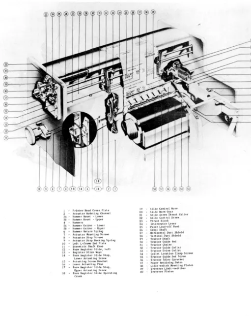
The PRINT HEAD (Figure 1-2) contains 130 hammer-actuatorassembliest one
for each print location. The actuator forcefully moves the hammer toward the associated typewheel at a precise instant selected by the electronic circuitry.
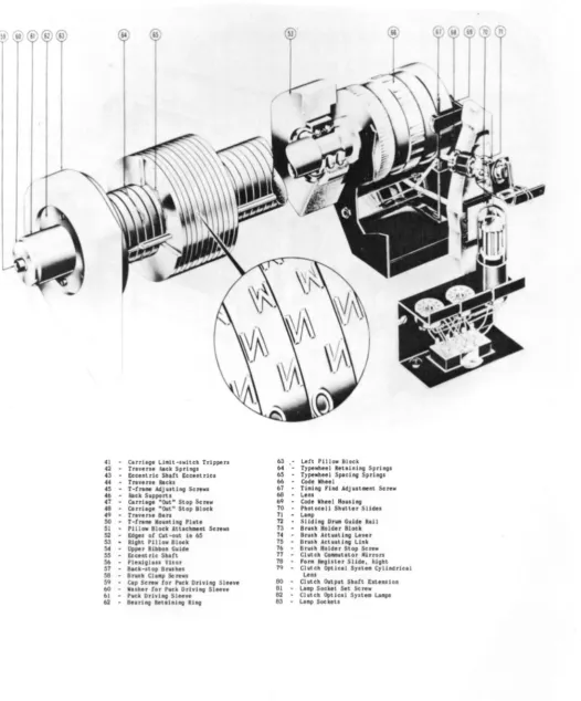
The TYPEWHEEL SHAFT ASSEMBLY (Figure 1-3) contains 65 double ... Qolumned typewheels and a Code Wheel with three independent polished optical facets. Each typewheel has two separate 51-character columns of type around the
circum-ference. Opposite each column is one hammer-actuator assembly on the Print
Head. The 65 typewheels print a 130-character line of print, with each
type-wheel printing in two adjacent print locations. The Code Wheel (Figure 1-3) establishes synchronization between the rotating typewheels and the character-selection circuits. The typewheel shaft is housed in a motor-driven carriage assembly (Figure 1-2) which moves in or out of printing position according to the setting of the CARRIAGE IN-CARRIAGE OUT switch on the Supervisory Control panel.
PX 616
o
1 PrJnter Head Cover Plale 2 .. Actuator Mounting Channel 3A Hanner Nount .. Lower
38.. Hanner Nount -Upper 4 HaJlllDerJ
5A HalllJle r Gu ides .. Lowe r 56.. Haaner GuJdes .. Upper b HaIDer f\eturn Spri ng 7 Actuator Mounting Screws 8 .. Actuator Stop Screw$
9 .. Actullor Stop Backing Spring 10 .. Lett L-Cr.ee End Pille 11 .. Eccent ric Shaft Knob 12 .. Fo .... Register Slide, Left 13 Reol"er Slide Ways 14 for. ~ister Slide Stop.
Lower Actuating Screw 15 .. Actuating Screw Bracket 16 .. Lever Actuating Pins
17 .. for. Register 51 ide Stop. Upper Actuating Screw
t8 for. R~hter Slide Operlting
Crank
19 SlJde Control Worm
20 Sllde Wor. Gear 21 .. Slide Screw Thrust Coll.r 22 Slide Cont rol Screw 23 Thus< Block
24 InterceptoT Lever 25 .. Paper Lead-oCC Hood
26 Cross Shat<
27 Hodoontal Dust Shield 26 Vertical Dust Shield 2Q Tractor Shift
30 Tractor Guide Rod
31 Tractor ChainS 32 .. Tractor Guide Collar
33 Tractor Drive Collet
34 Collet Location Clamp Screw,
35 Tractor Guide Set Screw
36 Tractor Idler Sprocket
37 Paper ke\aining Gates 38 Limit -switch Mounting Plates 39 Truerse U • .1t -switches
40 Traverse Pinion
Figure 1-2. Print Head Assembly
41 - Carriage LI.lt-.wltch Trippers
42 ... Trav., .. hick SprhOI
43 - E . . ent ric Shott Eccentric.
44 ... Trlve"e Rack.
45 - T-trl" AdJu.tlng Screw. 46 - Rack Supports
47 .. Cerrhge "Out" Stop Screw
48 Carriage "Out" Stop Block
49 ... Tnven. Bin
50 .. T-tr . . . Mo""ting Pitt.
51 - Pillow Block Atuch . . nt Screws 52 Edg.. oC Cut -out In 65 53 - Hight Pillow Block 54 - Upper Ribbon Guide 55 - Eocent ric Shltt 56 - Plexlgll .. Vllor S7 .. Slek-slop Brushe. 58 Bru.h CI •• p Screws
59 Cap Screw Cor Puck Driving Sle . . e 60 .. Wuher lor Puck Drhing Sleeye b} ... Puck DrivinG Sleeve
62 - Boorl ng Retol nl ng HI ng
63 Lett Pillow Block 64 Typewheel Retolnlng Spring' 65 Typewheel Sp.clng Spring' 66 Cede Whe.1
67 T1.lng find AdJ u,",ont Screw 68 .. Len.
69 - Code Wh.el H.u.lng 70 - Photocoll Shutter Slid .. 71 - L . . p
72 - Slid Ing Dr . . Guido Roll 73 - Bru.h Holder Block
74 BrYlh Actuating Liver
7S .. Bru.h Act"lting Link
76 BruJh Holder Stop Screw 77 .. Chltch CO_ulltor Mitrors
78 fono fltglltor Slide, hlght 79 - Clutch Optlc.1 Sylt •• Cyllndrlc.1
Len.
80 - Clutch Output Shott Exten,lon 81 .. LAap Socket Set Screw 82 - Clutch Optlc.l Syste. Lomp'
B3 - L.mp Soc keto
Figure 1-3. Typewheel Shaft Assembly
PX 616
6
o
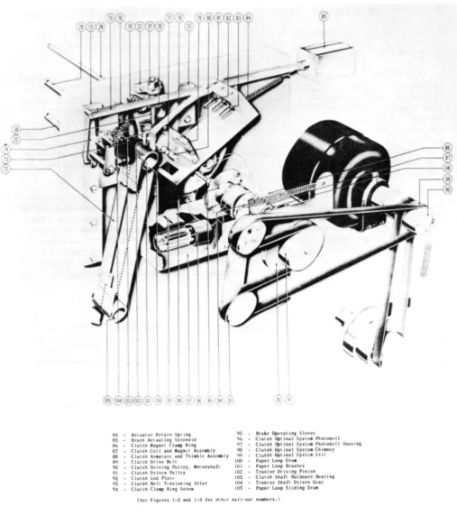
64 - Aclualor Return Sprlnv 1)5 85 - Brush ACluating Solenoid qb
8& - ClulCh M.gnel CIa.p Ring 97 87 CIUlCh Coj I and Maon'l "sseably 90
88 - Clutch "rallure and Thlable ASJelibly qq
89 ClulCh Drive Bell 100 90 - Clutch Driving P\llley. Motonhafl 101 eH ClulCh Driven Pulley 102 92 Clutch I:.nd Platt.' 103
q3 Clutch SelL Tl.'nsionlng Idler 104
94 - Clulch Cia"" Ring Screw 105
Brake Opent ing Sleeve
Clutch Optic~.1 Sylle. Pholocell Clutch Opllcal Syste. Photocell lIouslng
Clutch Optical SYSLe. Chiane), Clutch Opt tea 1 S)'llca Silt
Paper Loop Oru.
Paper Loop Brushes
Tractor Driving Pinion
Clutch Shaft Outboard Bearino Tractor Shafl Driven Gear
Paper Loop Sliding Oru. (Sec Figures 1-2 and 1-3 tor other nll-oul n"aben,)
The RIBBON FEED ASSEMBLY (Figure 1-2) controls feed of the ribbon past the Print Head. The ribbon is located between the typewheels and the paper; when a hammer from the Print Head strikes the paper, it forces the paper against the ribbon and typewheel, imprinting a character on the paper. Rate of ribbon feed is determined by printing speed, since the typewheel shaft furnishes the ribbon feed driving power. The direction of ribbon feed is opposite to the direction of rotation of the typewheel; the ribbon tends to clean the typewheel
characters as they pass.
The PAPER DRIVE ASSEMBLY (Figure 1-4) contains the mechanism for advancing the paper. ~he main drive motor supplies paper-feed power through a magnetic clutch and brake assembly t~ the tractor d~ive assembly (Figure 1-2), which in turn transports the paper past the Print Head. The paper feed commutator system (Figure 1-4) controls'operation of the clutch and brake assembly to produce paper feed in single~, double-, or t:riple-space increments. Paper may be "fast-fed" over areas where printing is not desired. Even during a Fast-Feed operation, however, paper always moves an exact multiple of the selected
line spacing. Paper advances at a rate of 22 inches per second regard"iess of
the distance moved. .
The PAPER LOOP ASSEMBLY (Figure' 1-4) contains a continuous paper loop which advances in synchronism with the paper. The loop may be any length between 66 and 132 lines, depending on the length of the p~per form being used for print-ing. The paper loop is divided vertically into twelve channels and horizon-tally into print lines. Each channel controls a specific machine function; a hole punched in a channel at a print line initiates the machine function con-trolled by that channel. Paper loop Channel.7 functions as a "Stop Homepaper" command. Channels 8 through 12 are not used. The remaining Channels (1 through
6) are described in Section 2~ paragraph 4.d. 4. BASIC OPERATION
a., UNIVAC CODE. - The information fed· into the High-Speed Printer must be expressed in the Univac code .. Each character in the Univac code is represented by seven binary digits and always cont~ins an odd number of "ones". Numerics are expressed in excess-three binary code; i.e., each numeric is represented by its binary value plus three.
In Univac code, the seven binary digits (bits) representing a character are divided into thr'ee 9roups: the body, zone, and check .pulse. The body is
formed by levels 1, 2, 3 and 4 of ·theinput tape; the zone by levels 5 and 6; and the check pulse .by lev~l 7. Characters are wri tten as shown in the follow-ing example for the character "A".
Univa6 Code Notation
7 65
o
01 Check Zone Pulse4321 Tape Level
0100
Body Code Group
The body and zone determine the character represented. The check pulse insures that the total number of ones in a character is always odd -- the check pulse contains a one only when the total number of ones in the body and zone is even.
PX 616
Since the body has 16 possible combinations and the zone has four, the two
together may form a maximum of 64 possible combinations. Of these 64
combin-ations, all but one are used; because of a Central Computer requirement, the
Printer does not use the combination 1 11 1111.
In the 63 combinations used
by the irinter, 51 represent printable symbols found on the typewheel, and the
remaining 12 represent non-printable special symbols. The combinations are
grouped as follows:
Printable Symbols
10 Numeric 26 Alphabetic
15 Punctuation
Non-Printable Symbols
4 Fast Feeds (FF I, FF II, FF III, FF IV) 1 Multiline (ML)
1 Stop
1 Breakpoint (BP)
5 Ignores
All of the printable symbols are found on the typewheel; as each symbol passes the Print Head, its code combination is produced by the Code Generator and applied to the Comparator.
None of the special symbols appear on the typewheels, nor are the code combinations of the special symbols produced by the Code Generator. When a special symbol enters the Printer from the tape, it is recognized and identi-fied as such by a function table which prevents the symbol from entering the Memory, and initiates operation of the special function circuitry for the par-ticular symbol. In normal operation, therefore, special symbols are not printed-out; those for Fast-Feed, Multiline, Stop, and Breakpoint initiate special
Printer functions, while ignore symbols produce spaces in the printed copy wherever they occur. When, for test purposes, it is desired to locate and identify the special symbols on the tape, they may be printed-out using the Computer Digit mode of operation. In Computer Digit operation, all special symbols are first altered to printable combinations, then fed into Memory and printed-out along with the printable symbols.
Table I shows the complete Univac code as used with the . High-Speed Printer. The special non-printable symbols are enclosed by parentheses in the "character" column. The print-out characters for the special symbols are listed in the "Computer Digit" column. Note that for each numeric the zone is "00", and the body is a binary number three greater than the value of the numeric.
b. OPERATION. - The typewheel drum (containing 65 typewheels) rotates continuously. Opposite each of the 130 type columns on the typewheel drum is a print hammer. Between the typewheel drum and the print hammers are the ribbon and the paper, in that order. When a print hammer is thrown forward by its actuator, it presses the paper and ribbon against the typewheel, imprinting a character from the typewheel onto the paper. During one revolution of the type-wheel drum, one complete column of type passes by each print hammer; one line
of print (130 characters) can thus be printed in just one typewheel revolution. After each line has been printed, the paper feed mechanism advances the paper
the desired number of spaces, and another line is printed. The ribbon advances at a rate proportional to the speed of the typewheel.
Proper operation of the Hi9h-Speed Printer requires that the mechanical assemblies function in synchronism with the electronic circuitry, so that the
information on the tape is correctly transformed into a printed output of the
desired format. The simplified block diagram (Figure 1-5) illustrates the
basic components of the High-Speed Printer. In a normal printing operation,
one blockette is read from the tape, stored in the Memory, transposed and trans-lated into the desired format, and printed. Each printing operation involves the completion of two cycles: a Read Cycle and a Print Cycle.
The beginning of a Read Cycle init~ates the paper feed, and starts the
Uniservo. The paper drive advances paper until the desired printing location is reached. The Uniservo reads a blockette into the input circuitry serially, one character at a time. The input circuitry transfers the blockette into
Memory. When the entire blockette (120 characters) has been read and stored
into Memory, the Uniservo stops., and the Read Cycle ends. The blockette re-mains stored in Memory until after completion of the Print Cycle.
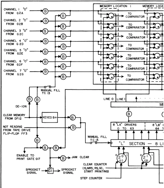
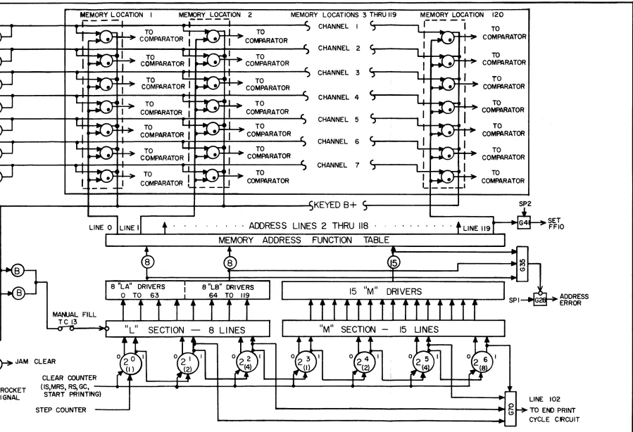
The end of the Read Cycle initiates a Print Cycle. The characters stored in Memory appear continuously as inputs to the Comparator. Also applied to the Comparator input is the Code Generator output, consisting of a coded com-bination identifying the typewheel character currently approaching the print
hammers. The Comparator contains 120 identical comparator stages; each stage
compares the Code Generator output with the seven-bit character stored in one specific Memory location. Each Comparator stage has a separate output line which can be connected through the plugboard to one or more hammer actuator drivers. The plugboard thus determines the output format, since it connects each Memory location through its associated Comparator stage to one or more print locations.
A Comparator stage generates an output signal when the associated character in Memory is identical to the Code Generator output. This Comparator output signal alerts the hammer actuator drivers in the print locations selected for that Comparator stage by the plugbo.ard. At the instant when a typewheel charac-ter is opposite the print hammers, a print signal samples all hammer actuator drivers, firing those which have been alerted by the Comparator. The fired drivers force the associated hammers against the typewheel, printing the charac-ter in all of the affected print locations. As each new typewheel characcharac-ter approaches the print position, the Code Generator sets up the appropriate code combination, and the Comparator alerts a new set of hammer actuator drivers. As each of the typewheel characters approaches and passes the print hammers,
the sequence of alerting the appropriate hammer actuator drivers from the Comparator and firing the alerted drivers with a print signal is repeated. During one typewheel revolution, all 51 characters pass the print hammers, and each Memory location containing a printable character generates one Comparator output signal when the character stored coincides with the Code Generator out-put. When one typewheel revolution has elapsed since the beginning of the Print Cycle, one line has been printed, and the cycle ends. At this time a Read Start signal initiates a Read Cycle, and a new printing operation begins.
PX 616
~
INPUT---0->
f-Q :
CODECIRCUITS MEMORY COMPARATOR
~
-
GENERATOR UNISERVO"21
....
T
$
cQ
J~
s::
~
-
.
SPROCKET ... MEMORYLOCATION
... CHANNEL
-
SELECTORI
c.n J~ J~
RE AD STOP
ST ART TAPE
END READ
PLUGBOARD
U'l ,f CYCLE
....
.a
.....,~
....
READ CYCLE~ H)
$
...
....
... c:r-
....
a
COMPLETE ~~ START
c:r-t= PRINT
PRINT CYClE
... .~
-
HAMMER0
n GATE
p!;"
0 ~PER FEED Jr
ACTUATOR
....
0) INIT IAL COMPLETE
END
DRIVER
PRINT CYCLE
co ....
-~
..
" a STA RTCONTROL
Bi
~ ,~
START PRINT HEAD
PAPER FEED PAPER
-
FEED-,
TYPEWHEEL. CODE
-c. SPECIAL FUNCTIONS. - Several of the special machine functions which add to the versatility and operating efficiency of the High-Speed Printer are dis-cussed briefly in this paragraph. More detailed explanations of the oper-ations are included in Section 2,
FAST-FEED - The Fast-Feed circuitry makes it possible to advance paper any desired number of spaces in one move without operator intervention. During a Fast-Feed operation, the paper drive system moves paper at the same rate (22
inches per second) as in normal line spacing. Of the five Fast-Feed circuits, four of them (Feed I through Feed IV) require the appropriate Fast-Feed symbol to be located as the first character in a blockette in order to start the Fast-Feed, and a hole in the proper paper loop channel to stop the Fast-Feed. Fast-Feed V starts and stops from holes in the paper loop. The six paper loop channels and the function of each are listed below.
PAPER LOOP CHANNEL FUNCTION
1 STOP FAST-FEED I
2 STOP FAST-FEED II
3 STOP FAST-FEED I I I
4 STOP FAST-FEED IV
5 START FAST-FEED V
6 STOP FAST-FEED V
A Fast-Feed symbol (FF I, FF II, FF III or FF IV) at the beginning of the
blockette commences paper spacing from an initial position. A hole encountered in the associated paper loop channel (Channell, 2, 3 or 4) stops the paper on the print line succeeding the hole location. A hole encountered at a given line in Channel 5 starts a Fast-Feed V from that line; the Fast-Feed V stops at the print line following the first Channel 6 hole encountered.
MULTILINE - A Multiline symbol in the first, second, or last character position of a blockette initiates operation of the Multiline circuitry. Under Multiline operation, one blockette is printed-out in any predetermined format on up to six successive print lines. A new Multiline symbol must be included in each blockette to be Multilined.
Plugboard and relay connections control the output format during Multiline operation. The plugboard is plugged in advance to determine the number of lines to be printed and the format of the information to be printed on each line.
STOP - A Stop symbol anywhere in a blockette stops Printer operation by preventing the beginning of a Print Cycle. When a Stop symbol enters from the tape, the read-in to Memory of the blockette containing the Stop symbol is completed, but the information contained in the blockette is not printed. The Printer must be started manually to resume operation at the point where it was stopped.
PX 616
BREAKPOINT - The effect of a Breakpoint symbol in a blockette is identical to that of the Stop symbol, except that a Breakpoint symbol will have no effect unless the BREAKPOINT switch is selected on the Supervisory Control panel. A Breakpoint symbol in a blockette is therefore an optional stop; it is ignored unless selected by the BREAKPOINT switch.
ZERO SUPPRESSION - The Zero-Suppression circuits replace non-significant zeros with spaces in pre-selected fields of the printed output. The Zero Suppression plugboard determines the location and size of each field where zeros are to be suppressed. Different fields may be selected for Single Line and Multiline operation.
d. ERROR-DETECTION CIRCUITS. - The High-Speed Printer contains numerous error-detection circuits to insure accurate transformation of information from the magnetic tape to the printed page. When a circuit or mechanical assembly fails to operate correctly, the associated error circuit functions to stop the Printer. The indicator for the error circuit lights, making possible rapid diagnosis and repair of the faulty circuit. The error circuits are described
briefly below. More detailed descriptions are included in Section 2, together
with numerous examples of operation.
ODD-EVEN ERROR DETECTOR - The Odd-Even error detector checks each character read from the tape to determine that it contains an odd number of binary "ones." If not, the error circuitry generates a "Prevent Print" signal, and the O.E. CHECK neon indicator lights. The Read Cycle is completed, but the Print Cycle cannot start.
120 ERROR DETECTOR - The Memory has a capaci ty of 120 characters. During each Read Cycle, a complete blockette containing 120 characters should normally
be read into Memory. If more, or less than 120 characters are read-in, the
error detector generates a Prevent Print signal, and the 120 CHEQ( indicator lights. (The ADDRESS CHEQ( indicator also lights, but should be ignored when
the 120 CHEQ( indicator is"onlt
) . When the error is a less-than-120 error, the
Uniservo does not stop at the end of the blockette where the error occurs, but reads-in the succeeding blockette also, this extra blockette not being entered
into Memory. The setting of the Memory Address Counter is usually helpful in
determining whether a greater-than-120 or less-than-120 error occurred.
ADDRESS-LINE ERROR DETECTOR - Before each character is read into Memory, a Memory Address is normally selected for the character by the Memory address circuitry. Failure of the Memory address circuits to select a Memory location for every character read-in results in the generation of a Prevent Print signal by the Address-Line error detector, and the lighting of the ADDRESS CHEQ( indi-cator. The Read Cycle is completed, but the Print Cycle does not start. The Address-Line error detector protects only against failure of the Memory address
circuits to select any address at all for an input character. Should one or more incorrect addresses be selected, multiple read-in to one or more addresses would occur, resulting in the storage of one or more non-printable combinations. Such an error would not appear during the Read Cycle as an Address Line error, but would occur as a Print Check error following print-out.
tremendous amount of paper before the error could be detected by the operator and paper-feed stopped manually. The paper-feed error detector prevents the feeding of more than 22 inches of paper in anyone paper-feed operation. If a paper-feed does not stop within one second (22 inches), the paper-feed error detector stops the paper drive, generates a Prevent-Print signal, and lights the P.F. CHECK indicator. Paper movement cannot start again until the START switch is actuated.
FAST-FEED ERROR DETECTOR - A tape-initiated Fast-Feed has precedence before a Fast-Feed V, by eliminating a Fast-Feed V if one is already in progress, and by preventing the initiation of a new one as long as the tape-initiated Fast-Feed lasts. Failure of a tape-initiated Fast-Fast-Feed to take precedence before the Fast-Feed V results in a Fast-Feed error, which generates a Prevent Print signal and lights the FAST FEED CHECK indicator. Read-in of the current block-ette is, however, completed. Normal printing operations may be resumed after a Fast-Feed error by actuating the START switch.
CHARGE ERROR DETECTOR - Each hammer actuator driver fires during the Print Cycle through an associated capacitor that has been charged during the Read Cycle from a +600 volt d-c ~ource. The start of a Print Cycle normally causes removal of the charging VOltage from the capacitors. Each driver can therefore fire just once through its capacitor during a Print Cycle. If the Start Print Cycle signal fails to remove the charging voltage, the Charge Error detector removes the charging voltage, starts paper feed, stops index pulses originating from the Code Generator, and lights the CHARGE CHECK indicator. The Printer stops in the middle of a Print Cycle, and paper is spaced.
PRINT ERROR DETECTOR - Associated with each print location are two tubes: a hammer actuator driver, and a check tube. Each check tube mo~itors the printing operation in the associated print location. At the end of the Print Cycle, the check tube will be out unless an abnormal printing operation has occurred. An abnormal printing operation could be the result of a non-printable combination stored in the Memory, failure to print a character, printing of an incorrect character, or printing of a character where there should be none. All of the check tubes are connected to the All-Out detector. When all check
tubes are extinguished at the end of a Print Cycle, the All-Out detector generates an All-Out signal, signifying that a normal print operation has occurred. If one or more check tubes are conducting at the end of a Print Cycle, no All-Out signal develops, and a Print Error signal is generated. The Print Error signal starts paper-feed, generates a Prevent Print signal, and lights the PRINT CHECK indicator (the A.O. DET. CHECK indicator is out). Examination of the printed line, the check tubes, and other components is usually helpful in diagnosing the cause of the Print Error.
ALL-OUT DETECTOR - Failure of the All-Out detector results in the gener-ation of a continuous All-Out signal, regardless of the state of the check tubes. The All-Out error detector checks the All-Out detector output at the beginning of each Print Cycle. If an All-Out signal is present, indicating failure of the All-Out detector, the Printer stops; all indicators will then be out with the exception of the A.O. DET. CHECK indicator, and the address counter will read 121.
PX 616
5. CONTROLS AND INDICATORS
Controls and indicators are located on three panels: the Supervisory Control panel, Test Control' panel, and Power Control panel. The Supervisory Control panel on the Printer unit controls normal Printer operation. The Test Control panel on the power supply unit is used in diagnosing and locating faults. The Power Control panel on the power supply unit is used to adjust and check the power supply. The following paragraphs explain the functions of the controls and indicators located on the three control panels.
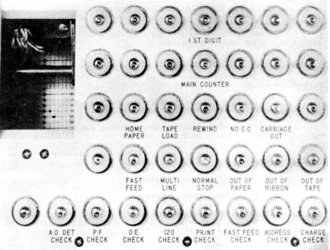
a. SUPERVISORY CONTROL PANEL. - The Supervisory Control panel conta ins one bank of switches and one bank of indicators, in addition to controls for the application of power. Figure 1-6, Supervisory Control Panel Controls, identifies the controls that are located on the Supervisory Control panel. Table 2 lists the controls and the functions of each.
The Supervisory Control Indicators, Figure 1-7, are located immediately above the Supervisory Control switches. These are used as aids in observing Printer operation and in diagnosing faults. The indicators and the functions of each are as follows:
1. FIRST ROW - 1ST DIGIT INDICATORS. - The seven indicators display the contents of the first Memory location. The check pulse indicator is at the left, followed by two indicators for the zone, and four indicators for the body of the Univac character. An illuminated indicator, representing a "1" in the Univac code, indicates that the corresponding Memory tube is not con-ducting. When d-c power is first applied, all 1ST DIGIT indicators should
light. One important use for the 1ST DIGIT indicator lies in the determination of the proper procedure to follow when an odd-even error occurs. It is neces-sary to know in this case, before operation can be resumed, whether a Fast-Feed symbol was in the first digit position or not, and if so, whether it was observed.
2. SECOND ROW - MAIN COUNTER INDICATORS. - The seven indicators display the condition of the Main Counter. The most significant digit·(26 ) is repre-sented by the left indicator, the least significant digit (20) by the right. After d-c power is first applied, all w~IN COUNTER indicators should be
extin-guished. After a 120-error occurs, these indicators may be used to determine whether a greater-than-120, or less-than-120 error has occurred.
3. THIRD HOW. - All indicators in the third row must be out before printing can start. The indicators are represented as follows:
HOME PAPER - Lights when the HOME PAPER switch is on. TAPE LOAD - Lights when the TAPE LOAD switch is on. REWIND - Lights when the REWIND switch is on.
NO D.C. - Lights when no d-c power is present. The indicator does not light unless a-c power is present.
CARRIAGE OUT Lights when the carriage is not fully in the normal operating position.
HO
ME
PA
P
ER
TAPE
L
OAD
START
ST
OP
OUT
INITIAL
SINGLE LINE
R
E:
AD
f
ORWARD
REA
D
BACKWARD
BREAK
POINT
HIGH
GAIN
LOW
GAIN
COMPUTER
DIGIT
CARRIAGE
IN
®
0
CARRIAG
OUT
PRIN
T
NO
READ
READ
NO
SPACE
PAPERFigure 1-6. Supervisory Control Panel Control~
PX 616
16
CONTROL
lOOP
GENER~L
•
CLEAR
4. FOURTH ROW. - The purpose of these indicators is self-explanatory.
FAST-FEED Lights when a Fast-Feed operation is in progress.
MULTILINE - Lights when a Multiline symbol is received; indicates that the Printer is performing, or is about to perform, a Multiline operatim.
NORMAL STOP - Lights when any condition other than an error stops the Printer. These conditions include:
(a) STOP switch on.
(b) Stop symbol encountered on tape during either Normal or Read, No Print operation.
(c) Breakpoint symbol encountered during either Normal or Read, No Print operation with the BREAKPOINT switch actuated.
(d) Fast-Feed I symbol encountered during a Read, No Print opera-tion initiated by the READ FORWARD/READ BACKWARD switch.
(e) End of 'tread-one-blocket forward" or "read-one-blocket te-backward" operation.
(f) End of Single Line operation.
(g) End of Space Paper operation.
(h) End of Home Paper operation.
(i) Out of Paper condition.
(j ) Out of Ribbon condition.
(k) Out of Tape condition.
OUT OF PAPER - Lights when end of paper supply is reached. NORMAL STOP indicator also lights.
OUT OF RIBBON - Lights when the end of the ribbon roll is reached. NORMAL STOP indicator also lights.
OUT OF TAPE - Lights when the end of the tape is reached. NORMAL
STOP indicator also lights.
5. FIFTH ROW. - The fifth row contains the error indicators:
A.O. DET CHECK - Lights when an All-Out detector error occurs. Indicates error only when it is the only error indicator lit, and the STOP indicator is not lit.
P.F. CHECK - Lights when a paper-feed error occurs.
A 0 OET P F
CHEC