R E S E A R C H
Open Access
Target estimation algorithm design using
quantity data and target feature
Chung-Lain Lu
*and Chih-Min Lin
Abstract
The estimation algorithm plays an important role in a radar tracking system. An improved estimation approach using both quantity data and target feature is investigated in this article. The advantage of this approach is that the system will have better estimation based on more target information. A data association denoted one-step conditional maximum likelihood algorithm is applied to match between radar measurements and existing target tracks. Moreover, an adaptive estimator is applied to combine the quantity data and target feature for estimation problems. According to the simulation results, this approach can enhance the performance of multiple-target tracking systems.
Keywords:Quantity data Target feature, Data association, Adaptive estimator
Introduction
In the tracking procedure, estimation algorithm is the key technique for multiple-target tracking systems. Once target measurements are received, an important process denoted data association must be applied to determine the exact associated relationship between measurements and predicted objects. In the literatures, some popular algorithms for data association were addressed, such as the joint probabilistic data association (JPDA) [1], one-step conditional maximum likelihood algorithm [2] and some applications using neural networks to tracking sys-tems [3,4]. In real applications, the moving targets usually include both maneuvering and non-maneuvering situations. If the targets are with maneuvering, the acceleration of targets usually causes the tracking in the radar system deviated from the trajectory. Consequently, how to detect and estimate the maneuvering status effectively is very important. The related techniques of tracking multiple maneuvering targets have been explored by some papers. An acceleration estimation algorithm based on the range rate measurement was developed in [5]. The interacting multiple model (IMM) methods [6] in target tracking applied two or more maneuver modes where the modes will be changed
during tracking procedure according to target situations. An approach using the multiple hypotheses for multiple target tracking was proposed by the literature [7].
In a dense target tracking environment, some targets can be very close to each other. The measurements pro-duced by these close targets can confuse the computa-tion algorithms and result in inaccurate target estimation. Data association algorithm is the key techni-que to solve this problem. However, the data association algorithms presented before only use the quantity data to determine the correlation between the measurements and the existing targets. If there is more information offered for radar systems, the tracking results can be more accurate. In this article, an approach using both quantity data and target feature is developed. In order to accurately estimate the targets, an image processing method [8-12] is applied to determine the features of the target and the tracking filter is applied to obtain the quantity data. Moreover, in order to combine these two different attributes, an adaptive estimator is applied to match between radar measurements and existing target tracks. Based on this approach, because there is more information offered for a radar system, therefore the more accurate tracking results will be obtained.
The rest of the article is organized as follows. The data association algorithm denoted one-step maximum likelihood approach is presented in“Data association
algorithm“ section. The image processing for tracking
* Correspondence: [email protected]
Department of Electrical Engineering, Yuan Ze University, Chungli 320, Taiwan, ROC
system is presented in “The image processing for
tar-get feature“ Section. An adaptive estimator is described in next section. The simulation results of multiple-target tracking are conducted in“Simulations“ section. The conclusions are drawn in final section.
Data association algorithm
The one-step conditional maximum likelihood algorithm [2] is applied to obtain the solution of the multiple get tracking problems. The mathematic model of a tar-get tracking system is defined as follows:
X(k+ 1) =F(k)X(k) +G(k)U(k) +W(k) (1)
Y(k) =H(k)X(k) +V(k) (2) whereX(k), state vector of the target;Y(k), measure-ment vector of the target; W(k), system noise assumed to be normally distributed with zero mean and variance Q(k); U(k), forcing input; V(k), measurement noise assumed to be normally distributed with zero mean and varianceR(k);H(k), measurement matrix of the target;F (k), transition matrix of the target; G(k), transition matrix of the forcing input.
For each step k, once an observation vector is received, the corresponding likelihood denoted as a weighting coefficient for each hypothesis can be obtained from one formula derived as follows. Let
Yk={Y(0),Y(1), ...,Y(k)} (3) βk={β(0),β(1), ...,β(k)} (4) whereb(k) is the vector whose entries consist of the uncertain parameters. Assuming that bk-1 is correctly identified andV(k), W(k) are Gaussian, the conditional probability density function ofY(k) based onbk-1,Yk-1is
p(Y(k)βk−1,Yk−1) = 1
(2π)m/2S(k)1/2
exp{−12τT(k)S−1(k)τ(k)} (5)
wheremis the dimension of the measurement vector, and
τ(k) =Y(k)− ˆY(k) (6)
S(k) =H(k)P(k|k−1 )HT(k) +R(k) (7) ˆ
Y(k) =H(k)Xˆ(kk−1) (8) These quantities can be obtained from the Kalman fil-ter equations. Suboptimal estimate can be computed,
with weights given by the corresponding likelihood functions, from Equation 9.
ˆ
X(kk) =
jp(Y(k)βkj(k) ,β
k−1,Yk−1)· ˆX(k|k,β
kj(k)) (9)
The image processing for target feature
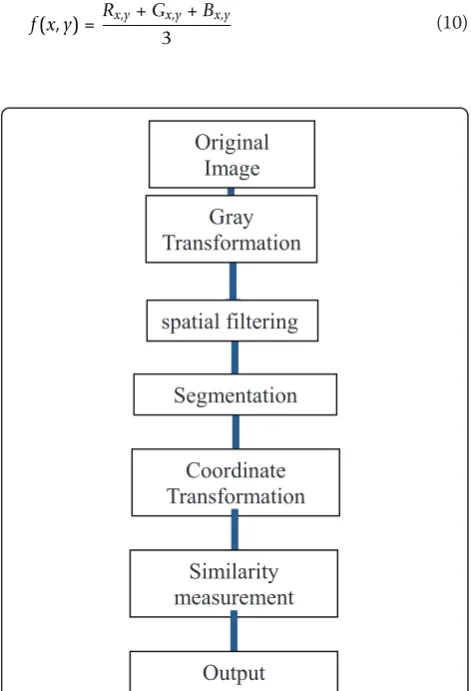
In this article, the image processing is adopted to iden-tify the target feature. And then the computation algo-rithm will calculate the similarity between the image of measurement and image of existing targets. The process of main works for conducting image processing is shown in Figure 1, and the descriptions are given as follows.
(1) Gray transformation and spatial filtering: In order to effectively determine the attribute of targets, the pre-processing step is used with image pre-processing method to determine the features of targets. In this way, more reli-able and more accurate of multiple-target tracking results can be obtained. In order to enhance the computation efficiency, when the sensor obtains the target images one equation (10) is applied to obtain the gray level.
f(x,y) =Rx,y+Gx,y+Bx,y
3 (10)
Coordinate
Transformation
Segmentation
Gray
Transformation
Similarity
measurement
Original
Image
spatial filtering
Output
Where f(x,y) is the image gray level, Rx,y is the red
color level,Gx,yis the green color level, andBx,y is the
blue color level, respectively. After the gray level of image is obtained, the spatial filtering or the neighbor-hood processing [9] is conducted to reduce the noise and enhance the edge of target image.
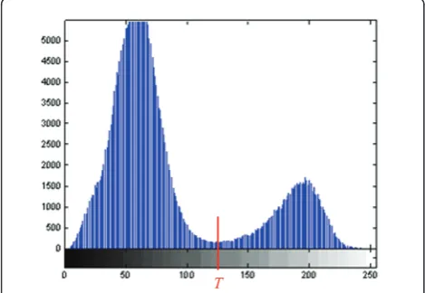
(2) Segmentation: This step is to identify the contour of the targets from the image. In order to segment the target feature from images, as shown in Equation 11 the thresholding method [9] is adopted to get rid of the noise from the image of the target. The global threshold diagram is shown in Figure 2.
g(x,y) =
0,fx,y<T
1, fx,yT (11)
whereTis the threshold.
Wavelet transforms (WT) [11] based image analysis is a valuable tool for image enhancement since it can be used to highlight scale-specific or sub-band specific image features. In addition, these features remain loca-lized in space, thus many spatial domain image enhancement techniques can be adapted for the WT domain. The WT domain contrast enhancement algo-rithms can be divided into manipulating the detail coef-ficient sets or the approximation coefcoef-ficient sets that result from WT decomposition. The latter manipulation mainly applies global histogram equalization to the approximation coefficient sets and then adds back the image’s small-scale high frequency features. Resulting from the phenomenon that the background gray-level concentrates in low intensity, this approach will degrade the image contrast. In order to enhance the intensity difference around the boundaries of the target, an edge-confined wavelet enhancement filter [10] is applied. To achieve this goal, edge detector is first applied on the image to extract the edges and then the wavelet
enhancement is selectively applied on the edges near the target boundaries.
(3) Coordinate transformation: The image of target may have different feature, therefore the system need take the coordinate transformation to match the relation of images. The operations include shift, enlarge, shrink, and rotation. The operations can be conducted by mul-tiplying the following matrices. Assume the original coordinate system is in the x-y plane and the trans-formed coordinate is in thex’-y’plane.
(i) Shift transformation matrix: ⎡
⎣ 1 0 00 1 0
xy1
⎤
⎦ (12)
Coordinate equation:
x=x+x
y=y+y (13)
(ii) Enlarge and shrink transformation matrix: ⎡
⎣s0x0 0sy0
0 0 1
⎤
⎦ (14)
Coordinate equation:
x=sx×x
y=sy×y
(15)
(iii) Rotation transformation matrix: ⎡
⎣−cossinθθ cossinθθ00 0 0 1
⎤
⎦ (16)
Coordinate equation:
x=xcosθ−ysinθ
y=xsinθ+ycosθ (17)
(4) Similarity measurement
After operating the segmentation and coordinate transformation, the similarity between the image of measurement and image of existing target can be obtained by using the computation logic denoted zero mean sum of absolute differences (ZSAD) [10]. The tar-get feature similarity can be calculated by Equation 18.
Tm(k) =
(i,j)∈w
X(i,j)−X−Y(i,j)−Y (18)
where Tm(k), similarity data; (X(i,j)), (i,j)th pixel of
measurement image; (Y(i,j)), (i,j)th pixel of template
T
image;X, average value of pixel of measurement image;
Y, average value of pixel of template image.
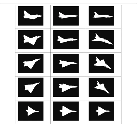
In the simulation, the M-2000 airplane is considered. The template image of M-2000 is shown in Figure 3. After the image processing, one fusion algorithm denoted adaptive estimator is applied to perform the computation of the radar estimation.
4Adaptive estimator
Targets usually take maneuver during the radar tracking process. This can lead to tracking error if the tracking sys-tem does not adopt maneuver detection and estimation algorithms. A maneuvering estimation algorithm together with a fusion algorithm denoted adaptive estimator is
developed in this article. In this approach, the similarity data of possible hypotheses are computed. Then, the Kal-man filtering technique is applied to take the state estima-tion based on the corresponding target. The proposed algorithm consists of a dynamic procedure which is applied to modify the parameters of the tracking filter to obtain more quick response for tracking. Such a dynamic procedure which modifies the tracking filter equations is described as follows. According to the tracking situation, the multiple targets’model can be defined as follows:
X(k+ 1) =F(k)X(k) +G(k)U(k) +W(k) (19)
Y(k) =H(k)X(k) +V(k) (20)
Let
τ(k) =Y(k)−H(k)Xˆ(k|k−1 ) (21)
I(k) =H(k)P(k|k−1 )HT(k) (22)
S(k) =I(k) +R(k) (23) whereτ(k) is the measurement innovation andS(k) is the innovation covariance matrix. In this algorithm, the components which have jumps are first detected using the following test
τi(k)KSii(k), for all i (24)
where the subscript imeans the ith component of a vector, andKis a constant related to the Gaussian prob-ability density function. The variance of the rejected innovation can be modified as
K2=τi2(k){ai(k)Iii(k) +Rii(k)}−1 (25) so thatτ(k) exists on the boundaries of the acceptable region defined by Equation 24. Thus, the parameter ai (k) can be computed as follows:
ai(k) =
[τii(k)/K]2−Rii(k)
Iii(k)
(26)
In order to keep the target in track, the covariance of the prediction errorP(k|k-1) is modified to [am
(k).P(k|k-1)], where am(k) is the largest value of all the ai(k).
Moreover, the similarity data of target feature based on Equation 18 will be adopted to modify the covariance matrix shown as following.
P(kk) =am(k) +C·Tm(k) v(k)−K(k)H(k)
P(kk−1)(27)
With this algorithm, the filtering gain is adapted based on the target situations. Based on this approach, the radar system can achieve more efficient and accurate estimations.
Simulations
In the simulation, the target motion models are assumed according to aerospace knowledge obtained from the popular aerospace textbook and articles. The quantity
data is computed by using the tracking filter to estimate the state vector. The target feature is conducted by the image processing. The results of tracking multiple tar-gets in the planar case are simulated under different situations. In the first simulation example, one target is chosen with the initial conditions as listed in Table 1. The maneuvering situations for the target are shown in Table 2. In the simulation, three different data associa-tion techniques namely, the JPDA [1], the CHNN [4], and the proposed algorithm in this article are applied for comparison. The simulation result of tracking one maneuvering target is shown in Figure 4. The tracking root mean square (RMS) errors of positions and veloci-ties are shown in Table 3. From Table 3, it can be seen that the proposed algorithm demonstrates better perfor-mance, with smaller averaged position errors and velo-city errors, than the other methods.
In the second simulation example, two targets are chosen with the initial conditions as listed in Table 4. The maneuvering situations for the targets are shown in Table 5. The simulation result of tracking two maneu-vering targets is shown in Figure 5. Their tracking RMS errors of positions and velocities are shown in Table 6. By comparing the results in Table 6, it can be seen that the proposed method is better than other methods. This experiment again demonstrates that the proposed method can achieve better performance for target tracking.
Table 1 Initial conditions of tracking one target
x(m) x˙(m/s) y(m) y˙(m/s)
Target 100 230 100 130
Table 2 Maneuvering status of tracking one target
Step 20~40 step 60~80 step other step
Acceleration a(x) (m/s2) a(y) (m/s2) a(x) (m/s2) a(y) (m/s2) a(x) (m/s2) a(y) (m/s2)
Target 50 -30 -50 30 0 0
Conclusions
An estimation algorithm using both quantity data and target feature is developed. A fusion algorithm denoted as the adaptive estimator is applied to combine the dif-ferent information. The advantage of this approach is
that because there is more information offered for radar systems, the tracking accuracy can be improved. The system will choose the corrected correlation between radar measurements and existing target tracks. Based on the simulation results, the proposed approach is capable of tracking multiple maneuvering targets with more accurate tracking results.
Abbreviations
IMM: interacting multiple model; JPDA: joint probabilistic data association; RMS: root mean square; ZSAD: zero mean sum of absolute differences.
Acknowledgements
The work was supported by the National Science Council under Grant NSC 98-2221-E-155-058-MY3.
Competing interests
The authors declare that they have no competing interests.
Received: 4 December 2010 Accepted: 23 May 2011 Published: 23 May 2011
References
1. KC Chang, CY Chong, Y Bar-Shalom, Joint probabilistic data and association distributed sensor networks. IEEE Trans Autom Contr.AC-31, 889–897 (1986)
2. E Emre, J Seo, A unifying approach to multi-target tracking. IEEE Trans Aerosp Electron Syst.25, 520–528 (1989). doi:10.1109/7.32084 3. D Sengupta, RA Iltis, Neural solution to the multitarget tracking data
association problem. IEEE Trans Aerosp Electron Syst.25, 86–108 (1989) 4. YN Chung, PH Chou, MR Yang, HT Chen, Multiple-target tracking with
competitive hopfield neural network-based data association. IEEE Trans Aerosp Electron Syst.43(3):1180–1188 (2007)
5. DF Bizup, DE Brown, Maneuver detection using the radar range rate measurement. IEEE Trans Aerosp Electron Syst.40(1):330–336 (2004). doi:10.1109/TAES.2004.1292169
6. E Mazor, A Averbuch, Y Bar-Shalom, J Dayan, Interacting multiple model methods in target tracking: a survey. IEEE Trans Aerosp Electron Syst.34, 103–123 (1998). doi:10.1109/7.640267
7. YN Chung, TC Hsu, ML Li, TS Pan, CH Hsu, A dynamic multiple-model estimator and neural algorithm for radar system. Int J Innov Comput Inform Control.31(2):4809–4817 (2009)
8. B Sugandi, H Kim, JK Tan, S Ishikawa, Real time tracking and identification of moving persons by using a camera in outdoor environment. Int J Innov Comput Inform Control.5(5):1179–1188 (2009)
9. RC Gonzalez, RE Woods,Digital Image Processing, 2nd edn. (Prentice Hall, Upper Saddle River, NJ, 2002)
10. Z Wang, EP Simoncelli, Translation insensitive image similarity in complex wavelet domain. IEEE Int Conf Acoust Speech Signal Process.2, 573–576 (2005)
11. JS Lee, YN Chung, Integrating edge detection and thresholding approaches to segmenting femora and patellae from magnetic resonance images. Biomed Eng Appl Basis Commun.17(1):1–11 (2005). doi:10.4015/ S1016237205000020
12. JA Besada, J Garcia, J Portillo, JM Molina, A Varona, G Gonzalez, Airport surface surveillance based on video images. IEEE Trans Aerosp Electron Syst. 41(3):1075–1082 (2005). doi:10.1109/TAES.2005.1541452
doi:10.1186/1687-6180-2011-7
Cite this article as:Lu and Lin:Target estimation algorithm design
using quantity data and target feature.EURASIP Journal on Advances in
Signal Processing20112011:7.
Table 3 RMS error of tracking one target
Position error(m) Velocity error(m/s)
Method 1 136.7 32.6
Method 2 132.1 29.7
Method 3 107.9 27.8
Table 4 Initial conditions of tracking two targets
x(m) x˙(m/s) y(m) ˙y(m/s)
Target1 100 230 100 130
Target2 100 130 300 200
Table 5 Maneuvering status of tracking two targets
Step 20~40 step 60~80 step other step
Acceleration a(x)
(m/s2) (m/sa(y)2) (m/sa(x)2) (m/sa(y)2) (m/sa(x)2) (m/sa(y)2)
Target1 50 -30 -50 30 0 0
Target2 50 -30 -50 30 0 0
Table 6 RMS error of tracking two targets
Position error(m) Velocity error(m/s)
Method 1 Target1 135.7 32.7
Target2 136.3 33.3
Method 2 Target1 125.9 30.9
Target2 123.8 29.1
Method 3 Target1 110.1 27.9
Target2 113.7 28.2