Division of Mines and Mineral Resources -
Report
1991111
Control of the Teac tape replay unit (Revision 1)
by
R.J. Sedgman
Abstract
A Teac tape replay unit was installed to transfer SIE down-hole logger data from cassette tape to a standard 9-track computer tape for archi ve and data manipulation. A microcomputer was employed to allow more reliable control and less overhead for the minicomputer.
INTRODUCTION
To allow data from the SIE down-hole logger to be archived and distributed in a standard format the logger tapes must be
transcribed onto standard 9-track computer tape. The method adopted to transfer data recorded on the SIE cassette tapes to a minicomputer was via the TEAC MT-2 tape transport system. Direct connection and control was not possible, due to the nature of the Teac tape drive and the minicomputer, so the control and transfer of data is handled via a microcomputer.
CHAPTER 1
Overview of the Teac tape replay system
The TEAC MT-2 cassette magnetic tape unit is designed to replay cassette tapes which comply with ISO, JlS, ECMA and ANSI standards. It is designed to allow intercbangeability of cassette tapes with tape units with the above standards. It has a basic command set which allows control of the tape unit and interrogation of internal registers. Connection to the unit is via a 50-pin flat connector, which also supplies power from an external source.
Control of the Teac tape unit is via a microcomputer. This computer converts commands from a control program called Wit. Three 8-bit control buses link the Teac tape unit via the 50-pin flat connector and a simple interface board in the microcomputer.
Data is then transfered to a minicomputer using a communications package which allows file transfers to take place.
CPU
Main System
REPORTl99l!1l
FIGURE
1.1.
Overview of system operationMTU
MTC CMT
2/20
I
CHAPTER 2
The Teac Tape Replay Unit
INTRODUCTION
The Teac Tape Replay Unit is basically used to extract data from a cassette tape and transfer dlis data to a controlling computer. The details on how dlis system functions are given in as much simplistic detail as possible in die following chapters. A knowledge of logical operations and bit manipulation is essential to understand die operation of controlling die unit It has been found dlat if dlese instructions are not adhered to by die letter. control of die unit is virtually impossible. Some of die features of die unit have been deliberately left out, as dley do not apply to dlis application. For details on die range of capabilities refer to die TEAC MODEL MT-2 Instruction Manual.
GENERAL DESCRIPTION
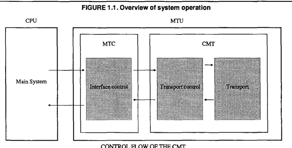
The MTU (magnetic tape unit) is divided into Ihree parts according to dleir functions. These are transport, transport electronics. and interface control. In die following. die transport and transport electronics are referred to as die CMT. and the interface control is referred to as the MTC.
The CMT is controlled by a main system (called the CPU). in this case a microcomputer. All error handling is performed by the microcomputer program.
Logic levels shown in this section of the manual are "I" (ground. 0 volts) and "0" (+5 volts).
An
example is a clock pulse shown to go high then low when the resulting physical output control voltage would be 0 volts then +5 volts.CONTROL METHOD
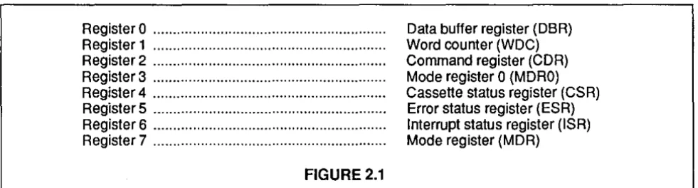
The MTC has eight registers to be accessed by the CPU. Each of these registers has particular significance for the control of the MTU by selecting different functions using these registers. There are 8 registers in the MTC accessible by the CPU; detailed descriptions are given later.
RegisterO ... . Register 1 ... . Register2 ... . Register3 ... . Register4 ... . RegisterS ... . Register 6 ... . Register 7 ... .
FIGURE 2.1
Data buffer register (DBR) Word counter (WDC) Command register (CDR) Mode register 0 (MORO) Cassette status register (CSR) Error status register (ESR) Interrupt status register (ISR) Mode register (MDR)
Control from the microcomputer is performed via Ihree 8-bit control busses. These busses are called ports and are labelled as PortA. Port B and Port C; they make upa 24-linedata bus. These are dlen divided into two groups (Data and Commands). Port B being Commands and Port A and Port C being data. Data is dlen divided into two parts (input and output). Port A being output and port C as input (input is here dermed as input to the microcomputer). As the data lines from the TEAC are both input and output (bidirectional) and use a 16-bit data bus. die microcomputer has to control electronically where the data from the TEAC is to go (this is a restriction placed on uS by the interface type. it does not allow bidirectional flow). The way dlis is doneis by using bit 7 on the PortB data lines to tell the interface between the 16-line data bus of die TEAC and the 24-line data bus which direction the data are flowing. The following diagram should explain.
Bit7 Bit 6 Bit 5 Bit 4 Bit3 Bit2 Bit 1 BitO
Port AlPort C Clock Select Read Interrupt Register Register Register
request select 2 select 1 select
a
FIGURE
2.2.
Port B
Bit7 BitS BitS Bit4 Bit3 Bit2 Bit 1 BitO
Data 7 DataS Data 5 Data 4 Data 3 Data 2 Data 1 Data 0
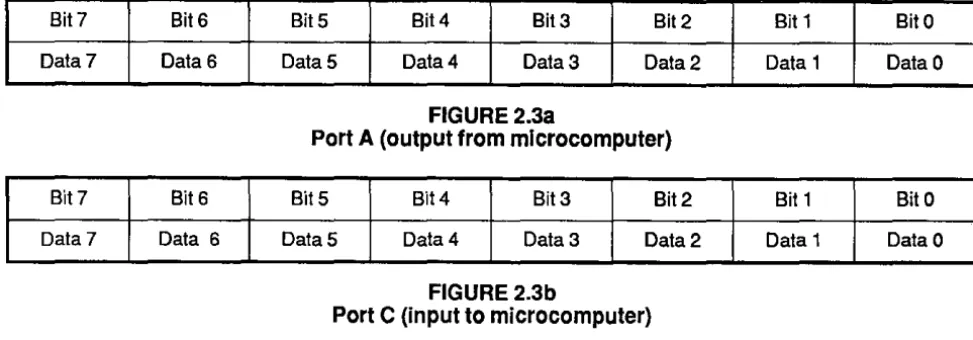
FIGURE 2.38
Port A (output from microcomputer)
Bit7 Bit S Bit S Bit4 Bit 3 Bit2 Bit 1 Bit 0
Data 7 Data S DataS Data 4 Data 3 Data 2 Data 1 Data 0
FIGURE2.3b
Port C (input to microcomputer)
Input!Output signals
(1) PortA. Data O-Data 7 Output signals. Eight signal lines to transmit data between the microcomputer and MTU.
(2) Port C. Data O-Data 7 Input signals. Eight signal lines to transmit data between the microcomputer and MTU.
(3) Select Input signal. Used to allow writing/reading to/from the internal registers.
(4) Register select 0-2 Input signal. Signals to select the registers in the MTU. Any of the eight registers may be selected with combinations of these three signals.
(5) Read Input signal. A signal to determine the direction of data transfer for byte Data O-Data 7.
(6) Clock Input signal. Used to determine the data transfer timing for all data transfers and input signals, except the reset command.
(7) Interrupt request. Output signal. A request from the MTU to the microcomputer signalling an Interrupt is required. Cleared after reading of the Interrupt Status Register.
(Timing diagrams· for interface only).
Internal Registers
Table 2.1 shows the registers in the MTU which are accessible to the microcomputer. One of the eight registers is selected by the microcomputer through the three register select signals. The data transfer direction is determined by the read signal from the microcomputer control program.
RS2 RS1 RSO REGISTER NO. REGISTERS ABBR. DIRECTION
0 0 0 RO Data Buffer Register DBR Input/Output
0 0 1 R1 Word Counter WDC Input/Output
0 1 0 R2 Command Register CDR Input
0 1 1 R3 Mode Register 0 MDRO Input
1 0 0 R4 Cassette Status Register CSR Output
1 0 1 RS Error Status Register ESR Output
1 1 0 RS Interrupt Status Register ISR Output
1 1 1 R7 Mode Register MDR1 Input
(Input is defined as input to the TEAC drive unit, Output is defined as output to the microcomputer.)
TABLE 2.1.
Function of Internal Registers.
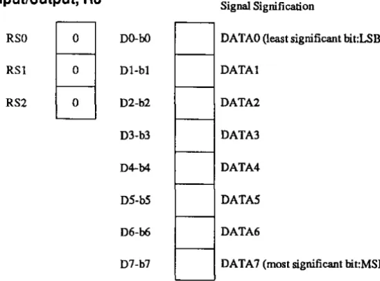
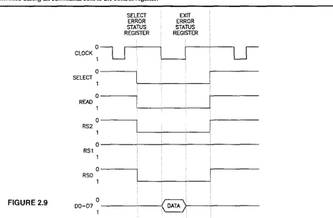
(1) DBR (Data Buffer Register) Input/output, RO
Signal Signification
RSO 0 DO-bO DA TAO (least significant bit:LSB)
RSI 0 DI-bl DATAl
RS2 0 D2-b2 DATA2
D3-b3 DATA3
D4-b4 DATA4
DS-bS DATAS
D6-b6 DATA6
D7-b7 DATA7 (most significant bit:MSB)
Read data from the cassette tape is transferred through this register. The contents of this register can be read out to the microcomputer at any time. Data transfer is a byte at a time.
FIGURE 2.4
o
CLOCK,
WORD
DATA BUFFER REGISTER
0 - - - , SELECT
,
O - - - i
READ
,
EXIT
DATA BUFFER REGISTER
O---~--~----~---RS2
,
O - - -_ _ _ L__~ _ _ L _ _ L _ _ _ _ _ ___
RS'
,
O----~-~--~---RSO
,
, Byte
DD-D7~---L---~,~~'---(2)
woe
(word counter) Input/output, R1 SignificationRSO I DO-bO 2°
~
RSI 0 DI-bl 2'
RS2 0 D2-b2 2'
DJ-b3 2'
D4-b4 2'
I---D5-b5 2'
D6-b6 2'
D7-b7 2'
WDC is a register only effective for the execution of control commands for data transfers. The number of Bytes to be transferred is determined by this register. The register is written every time before the input of the control command for the data transfer.
(a) The number of data values to be transferred is designated in Bytes, in this Case 252 Bytes are required.
(b) The register is a counter and the contents are decremented by each data transfer request from the MTC to the microcomputer. Therefore it is easy to find out how much data has been transferred by reading the contents of this register.
SELECT EXfT
WORD WORD
COUNT COUNT
REGISTER REGISTER
CLOCK~U
LJ
0
SELECT
,
0
READ
,
0
RS2
,
0
RS'
,
0
RSO
,
FIGURE
2.5
0(
)
00-07
,
DATA(c) Writing and reading into or from this register can be done anytime.
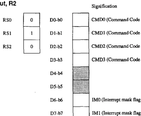
(3) CDR (command register) Input, R2 Signification
RSO
o
DO-bO CMDO (Command Code 0)RSI Dl-bl CMDl (Command Code I)
RS2
o
D2-b2 CMD2 (Command Code 2)D3-b3 CMD3 (Command Code 3)
D4-b4
DS-b5
D6-b6 IMO (Interrupt mask flag 0)
D7-b7 IMI (Interrupt mask flag 1)
By writing a control command code to Bits CMDO (bO) to CMD3 (b3), the MTU is instructed to start its operation. At the same time, write IMO (b6) and IMI (b7) to mask or not mask the interrupt during the execution of the control command.
Once a control command is written to this register, a new control command will not be accepted until the completion of the previous command.
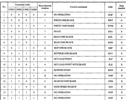
(a) Command Codes (CMDO-CMD3)
Table 2.2 shows the conlrol command codes; detailed descriptions of the conlrol commands are given in the section Command Code Registers.
(b) Interrupt mask flag a (IMO)
This flag is set to I to disable the Interrupt request flag. as data lransfers use the Data Available (DA) flag (explained later) instead.
(e) Interrupt mask nag 1 (lM1)
This flag is set to 0 to enable the conlrol command end flag (explained later) to be used for MfU conlrol.
Command codes Hexa-decimal
Data
No. Control commands Abbr
1
2
3
4
5
6
7
8
9
10
11
12
13
14
15
16
CMD3 CMD2 CMDl CMDO notation transfer
0 0 0 0 0 NO OPERATION NOP
0 0 0 1 1 WRITE ONE BLOCK WRT
0 0 1 0 2 WRITE TAPE MARK WTM
0 0 1 1 3 ERASE ERA
0 1 0 0 4 READ ONE BLOCK RDL
0 1 0 1 5 READ ONE BLOCK RDH
0 1 1 0 6 SKIP ONE BLOCK SKP
0 1 1 1 7 REVERSE ONE BLOCK REV
1 0 0 0 8 SET LOAD POINT SLP
1 0 0 1 9 SET LOAD POINT WITH ERASE SLE
1 0 1 0 A REWIND START REW
1 0 1 1 B NO OPERATION NOP
1 1 0 0 C SEARCH TAPE MARK STM
1 1 0 1 D HIGH SPEED SEARCH HSS
1 1 1 0 E NO OPERATION NOP
1 1 1 1 F NO OPERATION NOP
Note: The mark '0' in the colurrm of data transfer indicates that the command accompanies data transfer. The mark 'X' indicates that the command does not accompany data transfer. The commands No.5 and No.6 are the
same command (READ ONE BLOCK). The command codes for these are only distinguished by the abbreviated
command name.
TABLE 2.2
Control commands and codes.
X
0
X X
0
0
X X X X X X X X X X
FIGURE 2.6
SELECT COMMAND REGISTER
CLOCK~U
0---1 SELECT
EXIT COMMAND REGISTER
O---~---~---READ 1
o---~----~---~---RS2 1
0---,
RSl
1
O---~--~---RSO
1
00-07 0 _ _ _ _
-'-_---«
DATA ),... _________ _1 ~----~.
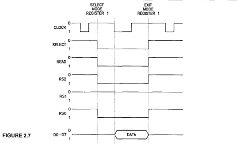
(4) MORO (Mode Register 0) Input, R3
Not used (only needed for DMA transfers and software reset)
(5) MDR1 (Mode Register 1) Input, R7
Signification
RSO DO-bO '0'
RSI DI·bl CFRE (CONTROLLER FREE REQUEST (CPR) ENABLE)
RS2 D2·b2 CFRIM (CPR INTERRUPT MASK FLAG)
D3-b3
D4-b4
DS-bS
D6-b6
D7-b7
Bit bO must be '0'
(a) CFRE (controller free request enable)
If Ihis flag is set to 'j', CFR (conIroller free) is set when the MTC becomes free. The condition ofMTC free means that no control command is given and the MTU completely stops.
Used only for controlling the unloading of a casselIe from the MTU.
(b) CFRIM (Controller free interrupt mask flag)
Not used.
(-';{3~
SELECT EXIT
MODE MODE
REGISTER REGISTER
CLOCK~U
LJ
,0 SELECT
1
0 READ
1
0
RS2 1
0
RSl 1
0
RSO
0
<
)
FIGURE 2.7 00-07 DATA
1
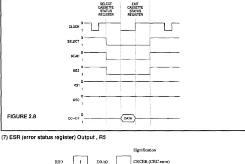
(6) CSR (cassette status register) Output. R4
Signification
RSO 0 DQ.bO EOT (end of tape)
RSI 0 DI·bl TM (tape mark delec!)
-RS2 D2·b2 FPT (file protect)
m·b3 CSD (cassette side)
D4·b4 NRDY (no! ready)
-D5·b5 0 '0'
-D6·b6 0 '0'
D7·b7 ERR (error s talus)
This register should NEVER be written to as some of the data bits may be reset.
(a) EOT (end of
tape
flag)EOT must be looked at after every control command so as not to allow the MTU to run off the rails.
(b) TM
(tape
mark)The flag is set when one of the following conditions are satisfied:
(i) Tape mark detected by Read one Block command
(ii) Tape mark detected by Skip one Block command
(iii) Tape mark detected by Search tape Mark command.
This flag is reset after the CSR is read.
(c) CSD (cassette side)
The flag shows which side of the cassette
is
being read, i.e. '0' Side A, 'I' Side B.(d) NRDY (not ready)
The flag is 'I' when the cassette is not ready or '0' when all conditions are satisfied for normal operation.
(e) ERR (error status)
Shows if an error has occurred, if this is true, i.e. 'I' then the ESR (error status register) should be read. This flag is reset w hen the ESR is read.
FIGURE 2.6
SELECT
CASSmE
STATUS REGISTER
CLOCK~-U--0---,
SElfCT
0---,
REAO 1
0 - - - - ,
RS2
EXIT CASSETTE
STATUS REGISTER
O---~-~--~---RS1 1
O---~-~--+--~---RSO 1
00-07 0
---'---i8>-. __ '-___ _
(7) ESR (error status register) Output, RS
Signification
RSO 1 DO-bO CRCER (CRC error)
RSI 0 Dl-bl RTlMER (read timing error)
RS2 1 D2-b2 WTIMER (write timing error)
D3-b3 (pPER (preamblelposlamble error)
D4-b4 WDCER (word count error)
D5-bS LIBGO Oong IBG 0)
D6-b6 LIBG 1 Oong IBG 1)
-D7-b7 0 '0'
-Various error-checks are performed in the MTU during the execution of a control command. If an error or errors are detected by the error checks, the causes of errors are indicated in this register. When the contents of this register are read the errors are cleared.
This register should NEVER be written to, as the data will be lost.
A II error handling and actions are handled by the high level control programs, so the only thing is for the programmer to know what each error is and how to fix it.
[O/3b
(a) CRCER (Cyclic Redundancy Check Error)
CRC checking is only performed during the execution of the Read One Block command.
(b) RTiMER (read timing error)
Read timing is checked only during the execution of a Read One Block command.
If this error does occur then the microcomputer program is at fault, and the section on the microcomputer program should be read.
This error occurs when the MTC is giving out data faster than the microcomputer control program can read it The maximum time allowed between the Data Available signal and Data Read is approximately 54.0 microseconds.
(c) WTIMER (write timing error)
Not used.
(d) PPER (preamble/postamble error)
Only checked during Read One Block command.
(e) WaCER (word count error)
Only checked during Read One Block command.
The MTC compares the number of data bytes from the cassette tape with the number previously written in the register WDC before the input of the Read One Block command, and if both numbers do not match, the flag is set to 'I'.
If the number of data bytes actually read is greater than the number written in WDC, data transfer requests equal to the number written in the WDC are supplied to the microcomputer and the residual data are ignored.
m
UBGO (long inter block gap 0)
This check is performed during the execution of High Speed Search.
(g) UBGI (long inter block gap
I)
Checked during all commands sent to the control register.
FIGURE
2.9
REPORT 1991/11
SELECT ERROR STATUS REGISTER
CLOCK
~LJ
0---, SELECT
0---,
READ 1
0 - - - ,
RS2
1
EXIT ERROR STATUS REGISTER
O---~---RS1
1
0 - - - ,
RSO
1
DO-D7~---~----~~~.
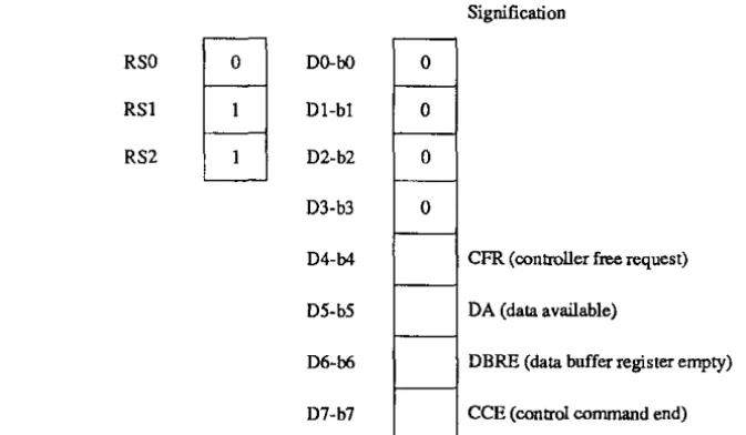
(8) ISR (interrupt status register) Output, R6
RSO
a
DO-bORSI DI-bl
RS2 D2-b2
D3-b3
D4-b4
D5-b5
D6-b6
D7-b7
a
a
a
a
Signification
CFR. (controller free request)
DA (data available)
DBRE (data buffer register empty)
CCE (control command end)
'/ b
3
If a request to the microcomputer for service occurs in the MTC, a flag corresponding to the request is set in this register.
When the microcomputer reads the contents of the register, the contents are automatically cleared.
NEVER write to this register, as the contents may be cleared.
(a)
CFR
(controller free request)If CFRE is ']' . the CFR flag is set when the MTC is free or when it becomes free.
(b) DA (data available)
This flag is only effective during the execution of Read One Block command. This flag cannot be set during the execution
of other control commands.
The MTC sets this flag to '\' to request the services of the microcomputer to transfer each byte to the microcomputer of read data (\ Byte) off the cassette tape from the register DBR.
SELECT EXIT INTERRUPT INTERRUPT
STATUS STATUS REGISTER REGISTER
CLOCK~U
LJ
a
SELECT
,
a
READ
1
a
RS2
,
0
RSl
a
RSO
,
FIGURE 2.10 0
(DATA)
00-07
,
(c) DBRE (data buffer register empty)
Only used for writing to tape.
(d) CCE (control command end)
This flag is set when all the basic operations of each control command are completed and the MTC is ready for receiving the next control command.
This flag is set on completion of each control command except for the NOP command.
COMMAND CODE REGISTER (CDR)
Use of the command code register requires 8 data Bits (Bottom 8 bits of the 16 Bit word) along with Command Code Register instruction (Top 8 bits of the 16 bits word).
Command register diagram
The register has to be selected, with clock pulse high (Bit 14), then the instroction required (e.g. Set Load Point) along with a clock pulse low. To finish the instroction the clock pulse has to be sent high to exit from command mode. Then clock high then low, then clock high before next instruction (ALWAYS FINISH WITH CLOCK IDGH), e.g. set load point
(Bit 14 ~ clock pulse).
EXIT
COMMAND REGISTER
0
CLOCK 1
0
SELECT 1
0
ROO 1
0
RS2 1
0
R51 1
0
RSO 1
0
<
)
00-07 OATA
1
The notation used in this section may seem confusing, so a brief explanation will be attempted.
The notation (ISR, b5), refers to the Interrupt Status Register, Bit 5. EOT (bO) refers to the End of Tape marker or bit 0 of the register you are currently looking at.
Command codes: (NOP)
(WTM)
(WRT)
(ERA) (RDL) (ROB)
(SKP) (REV)
(SLP) (SLE)
(REW) (STM) (HSS)
REPORT 1991/11
No operation - does nothing
Write tape mark - not used in this application Write one block - not used in this application Erase - not used in this application
Read one block - reads one block of 252 bytes of data Read one block - as above
Skip one block - looks for next tape mark in slow forward mode Reverse one block -looks for previous tape mark in slow reverse mode
Set load point - move the tape in slow forward from BOT (begin of tape) to the load point marker Set load point with erase - not used in this application
Rewind start - rewinds tape in fast reverse to clear leader
Search tape mark - searches next tape mark in slow forward mode
High speed search - searches next tape mark in fast forward mode (not used) Read one block (ROL, ROB)
(1) Command codes (CDR)
b7 b6 b5 b4 b3 b2 bl bO
'-_1,_0----'_1_,0 _ _ _ _ 0_-'-_ _ -'---_0_"-_0_---'
b7 b6 b5 b4 b3 b2 bl bO
FIGURE 2.11
(2) Explanation of the command
Two commands (RDL and RDH) to read one block of data from the cassette tape are available,
Receiving this command, the MTU makes the tape run in slow forward mode and starts the read operation at the detection of a block. The read data are loaded in the register DBR in the form of bytes. Then the DA flag (ISR, b5) is set to "I". With each setting of the DA flag (ISR, b5), the contents of register WOC is decremented until it reaches
"0".
When the contents becomes "0", no data transfer request will occur even if the reading of data on the tape continues.(3) Check for the contents of the register CSR
When the microcomputer detects the completion of the command (CCE="I "), read the contents of register CSR and check the following flags.
(a) EOT (bO)
If the tape passes over the EOT hole in the time period from the starting of the RDL or RDH operation to the reading out of the contents of CSR, this flag is set to "I".
(b) TM (bl)
The "I" state of this flag indicates that the block read was a tape mark. In this case, WDCER (ESR, b4) has occurred and the ERR (CSR,b7) flag is set to "]".
(c) ERR (b7)
(i) When the block read was a tape mark (TM="]"), this flag is set to "I" as explained in the above item (b). It is required for the CPU to ignore the ERR flag in this case. Then be sure to read out the register ESR to reset WOCER. If it is not done, WOCER will maintain "]" until the end of the next command.
(ii) If this flag is "0" without the detection of a tape mark, the command has been executed correctly.
(iii) If this flag is "]" without the detection of a tape mark (TM="O"), it indicates thal an error or errors have occurred. In such event, read the register ESR to check the contents of the register ESR.
(4) Check for the contents of the register ESR
The following five flags are effective for RDL and RDH commands. Other flags are "0" at this time (see ESR register description).
(a) CRCER (bO)
(b) RTIMER (db])
(c) PPER (b3)
(d) WDCER (b4)
(e) LIBGI (b6)
(5) Precautions for controlling
(a) Remember to write the number of data bytes to be transferred into the register WDC. You may write the number any time before the first data transfer request (DA="]") from the MTU. However, it is usually written before input of a control command.
If an RDL or an RDH command is executed without the above designation, one data transfer request occurs whatever the contents of WOC may be and WDCER (ESR, b4) is set to "0" at the end of the command.
(b) Table 2.3 shows the number written in the register WDC and the number of the data on the tape. The table shows the case when the WDC is written to 100 and a block of 97 bytes-I03 bytes is
read.
CASE (A) (B) (C) (D) (E) (F) (G)
No. written in WDe 100 100 100 100 100 100 100
No. of actual read data 97 98 99 100 101 102 103
No. of data transfer request to micro 98 99 100 100 100 100 100
WDCER (ESR,b4) "I" "I" "I" "0" "I" "I" "I"
Residual No. ofWDC 2 I 0 0 0 0 0
TABLE 2.3
Number in
woe
and number of read data
(i) The cases (A) - (C) show that the number of data actually read is smaller than the number written in WDC. The case (D) shows that both numbers are equal. The cases (E) - (G) show that the number of data actually read is greater than the number written in WDC.
(ii) For the cases (A) - (C), the fIrst one byte of the CRC is transferred to the microcomputer. Preamble and postamble are not transferred in any cases.
(iii) The residual number ofWDC shows the contents of WDC at the completion of the command, the microcomputer can read the contents freely.
(d) Remember that only one data transfer request (DA="I") occurs when a tape mark is read.
(e) Recognition of a noise block
Any blocks which are shorter than 15 bits are recognised as noise blocks and they are ignored.
(I) If a CRCER (ESR, bO) or a PPER (ESR, b3) occurs, read the block again after executing a REV command.
(g) If RTiMER (ESR, bl) occurs, read the block again afler executing a REV command.
REVERSE ONE BLOCK (REV)
(1) Command code (CDR)
b7 b6
(2) Explanation of the command
b5 b4 b3 b2 bl
FIGURE 2.12
bO
A command to make the tape run one block in slow reverse mode. No data are transferred by this command. When the end of the reversed block is detected, CCE (ISR, b7) is set to "I" to inform the command end to the microcomputer.
Error checking for the blocks is not performed by the REV command.
(3) Check for the contents of the register CSR
When the microcomputer detects the end of the command (CCE="I"), read out the contents of the register CSR and check the following flags in the register.
(a) EOT (b0): If the tape passes over the EOT hole in the time period between the starting of the REV operation and the reading out of the contents of CSR, this flag will be resel.
(b) ERR (b7): If this flag is "0", it indicates that the command has been executed correctly. If it is "I", read the contents of the register ESR.
(4) Check for the contents of the register ESR
The REV command only checks for LlBG 1 (b6). Other flags maintain
"a".
(5) PrecauOons for controlling
(a) Recognition of noise blocks: Any blocks which are shorter than 15 bits are recognised as noise blocks and they are ignored.
(b) If a REV command is supplied before the fIrst block on the tape (BOT hole side), the tape runs passing over the BOT hole by about 400 mm and stops. In such event, LlBG 1 (ESR,b6) will be set to "I". Then if a forward run command is supplied from that stopped point, EOT (CSR,bO) will not be set to "I" even if a hole is detected. However,LlBG1 might be detected.
SKIP ONE BLOCK (SKP)
(1) Command code (CDR)
b7
(2) Explanation of the command
b6 b5 b4 b3 b2 bl bO
FIGURE 2.13
A command to make the tape run one block in slow forward mode. No data are transferred by the command. When the end of the skipped block is detected, CCE (ISR,b7) is set to "I" to inform the end of the command to the microcomputer.
By the SKP command, a tape mark is detected, while the error checks for the data block are not performed.
(3) Check for the contents of the register CSR
Read the contents of the register CSR and check the following flags in the register, when the microcomputer detects the end of the command (CCE~"I").
(a) EOT (b0): !fthe tape passes over the EOT hole in the time period fTOm the starting of the SKP operation to the reading out of the CDR contents, this flag indicates "I".
(b) TM (hI): When the skipped block was a tape mark, this flag is set to "I".
(c) ERR (b7): !fthis flag is "0", it indicates that the command has been executed correctly. !fit is "1 ",confIrm the contents of the register ESR.
(4) Check for the contents of the register ESR
SKP command only checks for LlBG I (b6). Other flags maintain "0".
(a) Recognition of noise blocks: Any blocks which are shorter than 15 bits are recognised as noise blocks and they are ignored.
SET LOAD POINT (SLP)
(a) Command code (CDR)
b7 b6 b5 b4 b3 b2 bl bO
1,0 _ _ _ --'._O_....l...._O_.L._O_...J
FIGURE 2.14
(2) Explanation of the command
A command to make the tape run in slow forward mode from the BOT side clear leader to the load point (initial position). Start any read operations for the cassette tape after executing this command. If the cassette tape is not wound up to the BOT side clear leader, execute a REW command first to wind the tape to the BOT side clear leader and then execute the SLP command.
Figure 2.15 shows the head and tape position after executing the SLP command.
I
,
I I
I •
14.5mm
I
I
I I
I I
Direction of tape
BOT hole
t
clear leader!
?
BOT side---~---~---~~---I
~
II
write head read head
FIGURE 2.15
(3) Check for the contents of the register CSR
When the microcomputer detects the end of the command (CCE="1 "), read out the contents of the register CSR and check for ERR (b7). EOT (bO) and TI (bl) flags maintain "0".
(a) ERR (b7): If this flag is "0", it indicates that the SLP command has been executed correctly. If it is "I ", read out the register ESR.
(4) Check for the contents of the register ESR
The SLP command only checks for LIBG I (b6). Other flags maintain "0".
(a) LIBG I (b6): If the BOT hole is not detected after a 22.0-24.5 inch (558.8-622.3 mm) run of the tape from the BOT side end of the clear leader, this flag is set to "I" to complete the command.
(5) Precautions for controlling
(a) If the SLP command is supplied when the tape is in magnetic tape area, the tape starts to run and if a hole is not detected during the 600 mm (approximately) run, LIBG I (ESR, b6) is set to "I" to complete the command. Even if a hole is detected within the 600 mm run, there is no way to distinguish the EOT hole from the BOT hole.
(b) If the SLP command is supplied in the EOT side clear leader, magnetic tape area is not detected and the CCE(ISR,b7) will not be set.
(c) The MTU accepts the SLP command even if a cassette tape is not inserted. The execution of the SLP command will be started when a cassette is inserted and NRDY becomes "0".
Be sure to confirm that the cassette to be inserted is wound up to the BOT side clear leader.
REWIND START (REW)
(1) Command code (CDR)
b7
(2) Explanation of the command
b6 b5 b4 b3 b2 bl bO
FIGURE2.16
A command to rewind the tape at fast reverse mode (45ips) to the BOT side clear leader end. When the execution of this command starts, CCE (ISR,b7) is set to "I" immediately and the starting of the rewind operation is informed to the
·/3(:,
microcomputer. If a new command is supplied after CCE="I", the new command will be executed successively after the completion of the rewind operation.
When you rewind the tape to remove the cassette from the MTU, no other operation is needed after confirming rewinding start eCCE="I").
(3) Check for the contents of the register GSA
The REW command does not check errors. TM(bl) andERR(b7) flags maintain "0". The EOT(bO) flag will be reset if an EOT hole is detected during the rewind operation.
From above reason you need not check the contents of the register CSR if it is not required for special purposes.
(4) Precautions foreontrolling
(a) The MTU accepts the REW command even if a cassette tape is not inserted. The execution of the REW command will be immediately started when a cassette is inserted and NRDY becomes "0". The CCE(ISR,b7) is set to "I" immediately after the starting of the command execution.
(b) For the detection of the rewinding operation end, CFR (ISR,b4) is available.
SEARCH TAPE MARK (STM)
(1)
Command code (CDR)
b7 b6 b5 b4 b3 b2 bl bO
1,0
_L __ --'--__
..L.-_O_"---_O---'FIGURE
2.17
(2) Explanation of the command
A command to make the tape run continuously at slow forward mode and to search the tape mark. When the tape mark is detected, CCE(ISR,b7) is set to "I" and the end of the command is informed to the microcomputer.
Error checking and data transfers of the blocks, except for the tape mark, are not performed by the STM command.
(3) Check for the eontents of the register CSR
!f the microcomputer detects the command end (CCE="I"), read the contents of the register CSR and check the following flags in the register.
(a) EOT (bO): !fthe tape passes over the EOT hole in the time period from the starting of the STM operation to the reading out of the CSR contents, this flag is set to "1".
(b) TM (bl): When the tape mark is detected, this flag is set to "I". ERR (b7) is "0" at this time.
(c) ERR (b7): When this flag is" 1", read the register ESR.
(4) Check for the contents of the register ESR
STM command only checks for LIBG 1 (b6). Other flags maintain "0".
(5) Precautions for controlling
(a) Recognition of a noise block: Any blocks which are shorter than 15 bits are recognised as noise blocks and they are ignored.
(b) Input a SKP command if you want to stop the STM operation after it is started. The MTU will execute the SKP command instead of the STM command and set the CCE (ISR,b7) to "I" to complete the command.
Never input a command except for the SKP. If it were given, troubles might occur.
(c) When an error OCCurs in the tape mark, the tape will be forwarded without a stop, as the block cannot be recognised as a tape mark.
HIGH SPEED SEARCH (HSS)
(1) Command code (CDR)
b7 b6 b5 b4 b3 b2 bl bO
1,0 _ _ _ - ' _ _ -'-_ _ 0_-'---_--'
FIGURE 2.18
(2) Explanation of the command
A command to make the tape run continuously at fast forward mode (45 ips) and to detect the tape mark. When the tape mark is detected, CCE (ISR,b7) is set to "I" and the end of the command is informed to the microcomputer.
(3) Check for the contents of the register CSR
If the microcomputer detects the end of the command (CCE="I"), read the contents of the register CSR and check the following flags in the register. Remember to ignore the TM (bl).
(a) EOT (b0): If the tape passes over theEOT hole in the time period from the starting of the HSS operation to the reading out of the CSR contents, this flag is set to "I".
(b) ERR (b7): If this flag is "0", it indicates that the command has been executed correctly. If it is "I ", read the register ESR.
(4) Check for the contents of the register ESR
HSS command only checks LIBGO (ESR,b5). Other flags maintain "0".
(5) Precautions for controlling
(a) How to detect the tape mark: As the tape mark pattern is not checked by HSS command, the tape marlc is recognised by the method in Figure 2.19.
This method utilises the differences in the block length, that the standardised tape mark in the various standards is 32 bits, minimum data block is
48
bits, and the maximum noise block recognised by theMTU
at fast mode is II bits.Noise Block
Tape Mark
Minimum data block
tl
t2
11 biLs or less
Postamble
32 bits
48 bits or more
FIGURE 2.19
(b) Start/stop distances: As the HSS command is executed at fast mode, the longer tape distance is required for start/stop operations than at slow mode. Be sure to insert a longer IBG than usual.
The tape length required to recognise the tape mark from the difference in block length after starting the HSS operations is 2.4 inches (60.96 mm) maximum. The tape length travelled from the trailing edge of the tape mark detected by HSS command to the point where tape completely stops is 1.9 inches
(48.26
mm) maximum.!
>'l3Co
STATUS INFORMATION
Status infonnation is indicated by registers CSR and ESR. Some of the status infonnation is always effective and some is not always effective, indicating the result of the control command. The status is alway acted upon by the minicomputer, so this section is to be read in conjunction with Chapter 4 (Minicomputer Control Program)
(1) Status always effective
The status FPT(CSR,b2), CSD(CSR,b3) and NRDY(CSR,b4) are always effective. Each of these status indicates the cassette tape condition. These status are usually checked before the execution of a control command.
(2) Status indicating the result of a control command executed
Table 2.4 shows the status information to be checked for each control command executed. The status in the table which has '0' (except for the status with asterisks) indicates that the checking is not done for the command.
(a) EOT (CSR,bO): The flag becomes effective after executing a control command except for REW, SLP, and SLE. The "I" state is maintained as long as the cassette tape is in EOT state (see table 2.4). The flag is reset by the inputofRST signal or by executing SRST (soft reset).
(b) TM (CSR,bl): The flag becomes effective after executing a control command of WTM, RDL, RDH, or STM. It is reset when the register CSR is read out. The TM flag indicates either "0" or "1" after the execution of the HSS command. However, either state "0" or "I" should be ignored.
(c) ERR (CSR,b7): The flag becomes effective after executing a control command except for REW and ERA, and is reset after the the register ESR is read out. When the ERR flag indicates "1", read the register ESR to conftrm its contents and to clear the contents for the execution of the next command. If the contents of ESR is not read out, it will be maintained after the execution of the next control command.
(3) Notes for table 2.4
(a) The table indicates the cases without operation errors and troubles of the MTU.
(b) The number with asterisk indicates that the checking is performed. However the status are as indicated in the table when no troubles occur in the MTC.
(c) A "0" without asterisk indicates that the checking is not perfonned.
(d) The status information with double asterisks (00) are ineffective. They should be ignored by the CPU side of operations.
Control Register CSR Register ESR
commands ERR TM EOT LIBGl LIB GO WDCERM PPER WTIMER RTlMER CRCER
b7 b1 bO b6 b5 b3 b2 b1 bO
WRT 1,0 0 1.0 '0 0 0 1,0 1,0 0 1.0
WTM '0 1,0 1.0 '0 0 0 0 0 0 0
ERA 0 0 1,0 0 0 0 0 0 0 0
RDL 1.0 1.0 1.0 1.0 0 1,0 1,0 0 1.0 1.0
RDH 1.0 1.0 1.0 1.0 0 1.0 1.0 0 1.0 1.0
SKP 1,0 1.0 1,0 1.0 0 0 0 0 0 0
REV 1.0 **0 OR 1 1.0 1.0 0 0 0 0 0 0
SLP 1,0 0 0 1,0 0 0 0 0 0 0
SLE 1,0 0 0 1,0 0 0 0 0 0 0
REW 0 0 0 0 0 0 0 0 0 0
STM 1.0 1,0 1,0 1.0 0 0 0 0 0 0
fISS 1,0 **0 OR 1 1.0 0 1,0 0 0 0 0 0
TABLE 2.4
INTRODUCTION
CHAPTER 3
Microcomputer interface
2°/3('
The microcomputer interface enables control of the TEAC tape unit through a Fortran control program. All control and error handling are performed by this program. The program is divided into 2 major parts:
(a) a subroutine called TEACCONT, which is used for control of the TEAC tape unit and error handling. The subroutine accepts instruction (or control) from the main part of the program.
(b) the main program (WIT), which gives instructions to the TEACCONT subroutine and reformats the data retrieved to that required for tape backup. This chapter will focus only on the control of the subroutine TEACCONT.
INSTRUCTION SET
The TEACCONT subroutine accepts the following instructions from the main program and translates them into TEAC control codes.
InstnJction Code (main program)
Read One Block Skip One Block Reverse One Block Rewind Set Load Point Unload
Search Tape Mark
BASIC OPERATION
The basic operation of the TEACCONT subroutine is as follows:
(I) On start up:
(i) Reset all program parameters (i.e. pointers, interrupts etc.).
(ii) Initialise and reset the TEAC tape unit.
(iii) Wait for a request to perform an instruction from the WIT subroutine
(2) On receiving a request to perform an instruction:
RDH
SKP
REV
SLP
UL STM
(i) Accept an instroction from the WIT subroutine and convert it into control signals for the TEAC tape unit.
(ii) Perform inslruction.
(iii) Act on any errors which may have occured and try and remedy the fault Return the error status to the WIT subroutine for further action if required.
PROGRAM STRUCTURE
The program is set up as a main program dealing with control and error handling of the TEAC tape unit. All commands are dealt with by subroutines designed to issue these instructions to the tape unit. These subroutines may then call up ancillary subroutines which may be shared by a number of command subroutines; these include error handling. clock pulses and tape unit control information.
DESCRIPTION OF CONTROL COMMAND SUBROUTINES
Main control routine (TEAC)
Sets up the interface between the microcomputer and the TEAC tape unit Is used to set up 16 oUlput lines and 8 input lines.
It also controls how the commands passed down by WIT (i.e. the main control section) are performed.
Read One Block (RDL or RDH)
The Read One Block command requires the most interaction between the 1EAC tape unit and the microcomputer. As data are transfered from the tape unit as 252 byte blocks, the microcomputer program has to be fast enough to read and store the data one byte at a time without handshaking or buffering. The time restrictions imposed by the this problem means that the program has to be as efficient as possible in terms of speed and not programming technique.
Upon receiving the command from the WIT subroutine to read one block of data, the 1EACCONT subroutine starts the Read One Block subroutine which acts in the following way:
(i) Writes to the tape unit Word Counter Register the number of bytes per block of data to be retrieved (Le. 252).
(ii) Reads the interrupt status register and checks for DA (data available) and CCE (control command end), and repeats this until one or the other is found.
(iii) If DA. then read one byte of data and store it in an array: if CCE, then end. (iv) Repeat (ii) until CCE
(v) Check for an error and act upon it. Try to read the block at least eight times.
(vi) Reformat the data into the correct format for the WIT subroutine. The correct format is that of one single 16 bit word for every two bytes of data.
(vii) Return this array of data to the WIT subroutine.
The Read One Block command is basically broken up into three sections (I) Set up the tape unit to replay one block of data
(2) Read and store in memory one block of data and act on any errors (3) Give this one block of data to the WIT subroutine in the correct format. The main control subroutine flow chart is shown in Figure 3.1.
The flow chart of the subroutine which is the most critical section of theRead One Block command is shown in Figure 3.2. The structure of this flow chart should be followed to the letter. Any deviation will cause drastic errors and possible loss of data.
Skip One Block (SKPBLI<) (fig. 3.3)
This command moves the tape forward one block of data in slow forward mode. It does not return any data to the WIT subroutine, however it does return the contents of the Error and Cassette status registers to the WIT subroutine computer for error handling and reports locally of the error detected.
Reverse One Block (REVBLI<) (fig. 3.4)
This command rewinds the tape in slow mode to the beginning of the previous block of data. No data is read and the contents of the Error and Cassette status registers are returned to the WIT subroutine for error handling and reports locally of the error detected.
Rewind Set Load Point (SETLP) (fig. 3.5)
This command fully rewinds the tape (to the clear leader) then moves it forward in slow mode until the load point marker is detected by the tape unit; the tape stops on that point No data is read and the contents of the Error and Cassette status registers are returned to the WIT subroutine for error handling and reports locally of the error detected.
Unload (REWeL) (fig. 3.6)
This command is similar to the REW command except for two major differences:
(i) The tape is rewound to the beginning of the tape (clear leader) and not moved forward to the Load PoinL (ii) The contents of the Error and Cassette status registers are not checked.
This command is issued only to remove a cassette tape from the Teac tape unit.
Search Tape Mark (SRCHTM) (fig. 3.7)
This command searches for the next tape mark that appears on the tape in slow forward mode. No data is read and the contents of the Error and Cassette status registers are returned to the WIT subroutine for error handling and reports locally of any errors.
ANCILLARY COMMANDS
Read Status Register (STATREG) (fig. 3.8)
Read the contents of the tape unit status register. The nature of the status register (cassette. error and interrupt) are determined by the calling routine.
Control command (CONTCOM) (ftg. 3.9)
Instructs the TEAC tape drive what instruction is to be carried out.
Write Word Counter (WORDCOUNT) (fig. 3.10)
The write word counter subroutine is used to tell the tape unit the number of bytes of data to be read as one block. In this case the number is 252. which is determined by the way the tape has been formated on recording. i.e. 252 bytes per block. Once data has been written to the word counter it is not read from or written to until the next block of data are to be read.
Teac Reset (TEACRST) (fig. 3.11)
Used on power up this subroutine establishes communication to the tape unitandresets all software control to the initialising state. Only used on start uP. not during normal operation.
Control Command End (CCE) (fig. 3.12)
The Control Command End subroutine is one of the most important of the ancillary subroutines. as it detects when an operation such as reverse one block. skip one block etc. has been completed. !fthis flag is not checked for it would be very easy for the tape unit to miss instructions from the microcomputer because it may be executing an operation whilst another instruction is passed onto it. and therefore miss the new instruction altogether. This CCE subroutine is to be used at the end of every control command subroutine before returning for another control command.
Errors (ERRORS) (fig. 3.13)
At the completion of all the command control subroutines (except unload) the results of the ESR and CSR are given to the WIT subroutine for error diagnosis. However some errors are acted upon locally or just reported locally.
Write data to the TEAC tape unit (OUT/O)
Writes data to the computer output port which is connected to the TEAC tape unit.
Read data from the TEAC tape unit (INIO)
Reads data from the computer input port which is connected to the TEAC tape unit.
[28 August 1991]
READ. STORE DATA
1 Block
RESET MEMORY POINTER
CLOCK
FIGURE
3.1
REPORT 1991/11
READ ONE BLOCK
GET NEXT
DATA
BYTE
CHANGE
ALL
1'S TO ¢'S
& ¢'S TO 1'S
PUT DATA IN
NEXT ARRAY
POSITION
READ
DATA
N
Y
FIGURE 3.2
SKIP ONE BLOCK
Go foward one block
Don't read data
CONTROL
COMMAND
SKIP
CLOCK
CONTROL
COMMAND
END
ERRORS
ACT
ON
ERRORS
FIGURE 3.3
REVERSE ONE BLOCK
Reverse
Do not read data
CONTROL
COMMAND
REV
CLOCK
CONTROL
COMMAND
END
ERRORS
ACT
ON
ERRORS
FIGURE 3.4
REPORT1991/11
REWIND
Rewind
set load point
CONTROL
COMMAND
SET LOAD
POINT
CLOCK
CONTROL
COMMAND
END
ACT
ON
ERRORS
FIGURE 3.5
24J30
UNLOAD (TAPE FROM TEAC) Rewind to clear leader
CLOCK
ACT ON ERRORS
FIGURE 3.6
SEARCH TAPE MARK
Look for next tape mark
Slow Forward
CONTROL
COMMAND
STM
CLOCK
CONTROL
COMMAND
END
ACT
ON
ERRORS
FIGURE 3.7
REPORT1991/11
REGISTER SELECT
Select correct register
ISR, ESR OR CSR
START)
t
SELECT
REGISTER
'V
WRITE
REGISTER
'v
READ
RESULT
\V
EXIT
REGISTER
t
CLOCK
_t
END
FIGURE 3.8
CONTROL COMMAND
Pass control commad
to Teac
START
t
SELECT
CONTROL
COMMAND
,
I,
WRITE
CONTROL
COMMAND
,
!.,
CONTROL
COMMAND
EXIT
'v
CLOCK
t
C
END
)
FIGURE 3.9
WRITE WORD COUNTER
252 Bytes per Block
START
r
SELECT
WORD COUNT
REGISTER
,I,
WRITE
252 IN
REGISTER
,I,
EXIT
WORD COUNT
REGISTER
,1/
CLOCK
r
( END ')
FIGURE 3.10
REPORT199111l
TEAC RESET
( START)
t
CALL
MDR{Il
,
"
SET
COMMAND
MODE
,I,
END
MDR{Il
'v
CLOCK
t
(
END
)
SOFTWARE
RESET
FIGURE 3.11
CONTROL COMMAND END
Wait until Cantol Command End
has been detected
N
MASK OU
DATA BIT
FIGURE 3.12
ERRORS
Get the current
error status
START
READ
CSR
SET ERROR
STATUS
READ
ESR
SET ERROR
STATUS
END
FIGURE3.13
REPORT1991ill
CASSETTE STATUS REGISTER
Read Register
&
store
REGISTER
SELECT
CSR
CLOCK
ERROR STATUS
Read Register
&
store
REGISTER
SELECT
ESR
CLOCK
2j/3b
INTERRUPT STATUS REGISTER
Read Register & store
REGISTER
SELECT
ISR
CLOCK
,...
~
c
z
W
D..
D..
c:(iii
E
...
.2
CDc.
~
FlL£ FlLE 1 IBGMARK
...
252 BYTES
0.7 m
HEADER BLOCK IBG RECORD BLOCK
BYTE t .. PACIaD BCJ} 'IU 1D ,
LONG
IBG FIL£
1 IBG
"
2 IBG FILE MARK
0.7 m
RECORD BLOCK N
,...I )
18 oms: (
- - - T - - - - ,
BYTIt: :I - '6 .. 4...,. D1CJf' BCD lISZR CONSTANTS
BTT8 11 - Z66 - 0
0.05 m 0.05 m 0.05 m 0.05 m
SCAN 14 SCAN SCAN SCAN
1 2 3
,-'
J
L
'--
-, -,
,-
'-,
,-
,-'
'-G
0 OJ...,
...."'
'"
"-~l
OJ
'"
...."' '"
"- <Xl 0>W W W W W W W W W W W W W W W W W
~
~ ~ ~ ~ ~ ~ ~ ~
>= <D~
>= <D~ ~
~ ~ ~
>= <DOEPTH CHANL 1 CHANL 2 CTR 1 CTR 2 REAL CHANL 1 CHANL 2 TIME
4 DIGITS 4 DIGITS 4 DIGITS 6 DIGITS 6 DIGITS 4 DIGITS 16 BITS 16 BITS
I
'"
PACKED BINARY CODED DECIMALI
2'S ----~;;.'I
COMPLEMENT BINARY,
LONGIBG lAST FILE IBG
FILE
MARK IBG
FILE MARK
I I I
LAST RECORD BLOCK 13
'fLUD rtrH ZEROS
AS NECESSARY
J
THE 2'S COMPLEMENT CONVERSIONS ARE 12 Brr WIDE AND ARE RECORDED DIRECTLY FROM THE A/O CONVERTERS, THE TOP FOUR
Brrs OF BYTES 15 AND 17 ARE ZEROS.
THE 4 DIGIT BCD CONVERSION VALUES IN BYTES .3 TO 6 ARE
COMPUTED FROM THE TOP 10 BITS OF THE 12 BIT A/D BINARY
VALUE.
NOTE THAT THE DATA IS NOT RECORDED ON TAPE IN ASCII AND IS
THUS NOT DIRECTLY COMPATABlE WITH MOST PRINTERS AND OTHER
[/J
-
CCS iC1 QI) .~ [/J QJ (.) CCS '+-< ;... QJ....,
P
.-;... QJ....,
;=:j P..S
0 (.) 0 ;... (.).-::g
REPORTl991111 BO B1 B2 B3 B4 B5 Bo B7 AO A3 C3 A4 A7 C7APPENDIX 2
Interface circuit diagrams
[5
Bit 8
Bit 9
Bit 10
Bit 11
Bit 12
Bit 13
Bit 14
Bit 0
Bit 1
Bit 2
[/J
-
CCSiC1 QI)
.~
Bit 3 [/J QJ (.) CCS '+-< ;... QJ
....,
pBit 4 .~
....,
.-
P
;=:jBit 5 QJ
P.. CCS
....,
(.) CCS QJ Bit 6 E-<Bit 7
APPENDIX 3
Olivetti computer control program
C
C THE OUTPUT DATA PORTS OF THE COMPUTER ARE DEFINED IN THE FOLLOWING WAY C
C PORT A C PORT B
C
DATA OUTPUT TO THE TEAC (USED TO LOAD TEAC REGISTERS) CONTROL OF CLOCK, REGISTERS, READ/WRITE, SEL.
BIT 7 OF THIS WORD IS RESERVED TO INFORM THE INTERFACE CARD THAT DATA IS TO BE INPUT ON PORT C OR OUTPUT ON PORT A. C
C C
C
C C
BIT 7
=
1 THEN INPUT PORT C. BIT 7=
a
OUTPUT PORT A.WHENEVER INPUT OR OUTPUT OF DATA ON PORT A OR PORT C IS REQUIRED BIT 7 HAS TO SET ON PORT B BEFORE HAND DEPENDING ON THE
DIRECTION OF DATA FLOW. PORTS A AND C SHARE A BIDIRECTIONAL BUS ON THE TEAC CONTROL BOARD.
C PORT C C
DATA INPUT FROM THE TEAC (USED TO LOAD TEAC REGISTERS)
C DEFINE COMMON DATA BLOCK BLOCK DATA BPORTS
IMPLICIT INTEGER*2(A-Z)
COMMON /PORTS/PORTA,PORTB,PORTC
DATA PORTA /524/,PORTB /525/,PORTC /526/ C OUTPUT PORTA AND B, INPUT PORTC
END
BLOCK DATA BSTAT IMPLICIT LOGICAL (A-Z)
COMMON /STAT/ERR,TM,EOT,LIBG1,LIBGO,WDCR,PPR,WTIME,RTIME,CRC C COMMON ERROR MESSAGES
END
BLOCK DATA BTEACDATA COMMON /TBLK/TDATA INTEGER*2 TDATA(126)
C DATA READ FROM TAPE IN BLOCK ASCII FORMAT END
C
C MAIN DRIVER SUBROUTINE FOR THE CONVERSION OF CONTROL COMMANDS C FROM WIT INTO TEAC COMMANDS
SUBROUTINE TEAC(COM)
COMMON /PORTS/PORTA,PORTB,PORTC
COMMON /STAT/ERR,TM,EOT,LIBG1,LIBGO,WDCR,PPR,WTIME,RTIME,CRC COMMON /TBLK/TDATA
INTEGER*2 PORTA,PORTB,PORTC
LOGICAL ERR,TM,EOT,LIBG1,LIBGO,WDCR,PPR,WTIME,RTIME,CRC INTEGER*2 ADDRESS,MODE,TDATA(126)
CHARACTER*3 COM
DATA ADDRESS /527/,MODE /137/ CALL OUTB(MODE,ADDRESS)
C SET UP COMPUTER DIGITAL OUTPUT BOARD SO THAT C PORT A AND PORTB ARE OUTPUT AND PORT C INPUT
CALL TEACRST
IF (COM.EQ.'STM') THEN CALL SRCHTM
ENDIF
IF (COM.EQ.'UL ') THEN CALL REWCL
ENDIF
IF (COM.EQ.'SLP') THEN
C SET LOAD POINT REQUIRES REWIND BEFORE SETLOAD POINT CALL REWCL
CALL SETLP ENDIF
IF (COM.EQ.'SKP') THEN
CALL SKPBLK ENDIF
IF (COM.EQ.'REV') THEN CALL RVBLK
ENDIF
IF (COM.EQ.'RDH') THEN CALL READONEBLK
ENDIF RETURN END
C OUTPUT INSTRUCTION TO RIGHT PORT
SUBROUTINE OUTIO(PORT,INSTRUCTION) INTEGER*2 INSTRUCTION,PORT
CALL OUTB(INSTRUCTION,PORT) RETURN
END
C INPUT DATA FROM PORT
SUBROUTINE INIO(PORT,INFORMATION) INTEGER*2 PORT,INFORMATION,INB INFORMATION-INB(PORT)
RETURN END
C CLOCK PULSE,HIGH,LOW,HIGH SUBROUTINE CLOCK
COMMON /PORTS/PORTA,PORTB,PORTC INTEGER*2 PORTA,PORTB,PORTC,HIGH,LOW DATA HIGH /127/,LOW /63/
CALL OUTIO(PORTB,HIGH) CALL OUTIO(PORTB,LOW) CALL OUTIO(PORTB,HIGH) END
C READ STATUS REGISTER, IS INFORMED BY THE CALL SUBROUTINE C WHICH STATUS REGISTER (ISR,ESR,CSR).
SUBROUTINE STATREG(SELSTR,READSTR,RESULT) COMMON /PORTS/PORTA,PORTB,PORTC
INTEGER*2 RESULT,SELSTR,READSTR,PORTA,PORTB,PORTC,TREST DATA TREST /127/
CALL OUTIO(PORTB,SELSTR) CALL OUTIO(PORTB,READSTR) CALL INIO(PORTC,RESULT) CALL OUTIO(PORTB,SELSTR) CALL OUTIO(PORTB,TREST) CALL CLOCK
RETURN END
C WAIT FOR CONTROL COMMAND END TO BE DETECTED SUBROUTINE CCE
INTEGER*2 RESULT,CCETRUE,SELISR,READISR LOGICAL FLAGCCE
LOGICAL TESTBIT
DATA CCETRUE /O/,SELISR /65/,READISR /129/ C BIT 0 OF ISR IS THE CCE FLAG
110 CALL STATREG(SELISR,READISR,RESULT)
FLAGCCE-TESTBIT(RESULT,CCETRUE) IF (.NOT. FLAGCCE) RETURN
C CHECK FOR CONTROL COMMAND END BEFORE RETURNING TO CALL ROUTINE. C .NOT. FLAGCCE EQUALS CCE HAS OCCURED.
GOTO 110 END
C WRITE TO WORD COUNTER TO COLLECT 252 BYTES OFF TAPE SUBROUTINE WORD COUNT
COMMON /PORTS/PORTA,PORTB,PORTC
INTEGER*2 WCOUNT,SELWC,WRITEWC,PORTA,PORTB,PORTC DATA SELWC /86/,WCOUNT /3/,WRITEWC /22/
C WCOUNT IS THE NUMBER OF BYTES TO BE READ, SINCE REVERSE LOGIC IS USED C WCOUNT-3, ie: THE COMPLEMENT OF 252
CALL OUTIO(PORTB,SELWC) CALL OUTIO(PORTB,WRITEWC) CALL OUTIO(PORTA,WCOUNT) CALL OUTIO(PORTB,SELWC) CALL CLOCK
RETURN
END
C TEAC RESET FOR STARTUP, SET COMMAND MODE AND NOT DMA CONTROL SUBROUTINE TEACRST
COMMON /PORTS/PORTA,PORTB,PORTC
INTEGER*2 SELMDRO,WRITEMDRO,PORTA,PORTB,PORTC,MDRORST INTEGER*2 MDR1INST,SELMDR1,WRITEMDR1,MDRONODMA
DATA MDRORST /109/,SELMDRO /84/,WRITEMDRO /20/,MDRONODMA /237/ DATA MDR1INST /249/,SELMDR1 /80/,WRITEMDR1 /16/
C BIT 0 OF MDRO DATA IS THE SOFTWARE RESET OF THE TEAC C BIT 4 OF MDRO DATA IS TO SET UP FOR NO DMA CONTROL
CALL OUTIO(PORTB,SELMDRO) CALL OUTIO(PORTB,WRITEMDRO) CALL OUTIO(PORTA,MDRORST) CALL OUTIO(PORTB,SELMDRO) CALL CLOCK
CALL OUTIO(PORTB,SELMDRO) CALL OUTIO(PORTB,WRITEMDRO) CALL OUTIO(PORTA,MDRONODMA) CALL OUTIO(PORTB,SELMDRO) CALL CLOCK
CALL OUTIO(PORTB,SELMDR1) CALL OUTIO(PORTB,WRITEMDR1) CALL OUTIO(PORTA,MDR1INST) CALL OUTIO(PORTB,SELMDR1) CALL CLOCK
RETURN END
C CONTROL COMMAND, WHAT TYPE OF COMMAND IS PASSED ON BY THE C CALLING SUBROUTINE.
SUBROUTINE CONTCOM(CONTROL) COMMON /PORTS/PORTA,PORTB,PORTC
INTEGER*2 SELCOM,WRITECOM,CONTROL,PORTA,PORTB,PORTC DATA SELCOM /85/,WRITECOM /21/
CALL OUTIO(PORTB,SELCOM) CALL OUTIO(PORTB,WRITECOM) CALL OUTIO(PORTA,CONTROL) CALL OUTIO(PORTB,SELCOM) CALL CLOCK
CALL CCE RETURN END
C READ IN ONE BLOCK OF DATA FROM TAPE
C THIS SUBROUTINE IS REQUIRED TO BE VERY QUICK SINCE THE TEAC DOES NOT C WAIT FOR THE COMPUTER TO CAPTURE DATA. ANY MODIFICATION TO THIS ROUTINE C CAN AND PROBABLY WILL CAUSE READ TIME ERRORS AND THE CORRECT DATA
C NOT RETRIEVED OFF TAPE. SUBROUTINE READONEBLK
COMMON /STAT/ERR,TM,EOT,LIBG1,LIBGO,WDCR,PPR,WTIME,RTIME,CRC LOGICAL ERR,TM,EOT,LIBG1,LIBGO,WDCR,PPR,WTIME,RTIME,CRC COMMON /PORTS/PORTA,PORTB,PORTC
INTEGER*2 PORTA,PORTB,PORTC,IBYTE,RESULT,READBLOCK,ICOUNT COMMON /TBLK/TDATA
INTEGER*2 SELISR,READISR,DAMASK,SELDBR,READDBR,CCETRUE INTEGER*2 SELCOM,WRITECOM,TDATA(126),TAPDATA(252) LOGICAL FLAGDA,FLAGCCE,TESTBIT
DATA SELISR /65/,READISR /129/,DAMASK /2/,READBLOCK /10/ DATA SELDBR /71/,READDBR /135/,CCETRUE
/0/
DATA SELCOM /85/,WRITECOM /21/
C CCETRUE ~ MASK FOR ISR BIT 0 (CONTROL COMMAND END) C DAMASK ~ MASK FOR ISR BIT 2 (DATA AVAILABLE)
C
ICOUNT~O
C FLAG FOR NUMBER OF RETRIES ATTEMPTED
100 IBYTE~O
C CURRENT NUMBER OF BYTES CALL WORD COUNT
C TELL THE TEAC THAT THE RECORD LENGTH IS 252 BYTES OF DATA
C TELL
110
C READ
CALL OUTB(SELCOM,PORTB) CALL OUTB(WRITECOM,PORTB) CALL OUTB(READBLOCK,PORTA)
TEAC TO READ ONE BLOCK OF 252 BYTES NOW CALL OUTB(SELCOM,PORTB)
CALL CLOCK
CALL OUTB(SELISR,PORTB) CALL OUTB(READISR,PORTB) RESULT~INB(PORTC)
IN INTERRUPT STATUS REGISTER CALL OUTB(SELISR,PORTB)
FLAGDA~TESTBIT(RESULT,DAMASK) FLAGCCE~TESTBIT(RESULT,CCETRUE)
IF (.NOT. FLAGDA .OR . . NOT. FLAGCCE) GOTO 120 C .NOT. FLAGDA ~> DATA IS AVAILABLE TO BE COLLECTED C .NOT. FLAGCCE ~> TEAC HAS FINISHED READ ONE BLOCK
GOTO 110
C NOT FINISHED YET SO GET A FRESH ISR
120 IBYTE~IBYTE+1
CALL OUTB(SELDBR,PORTB) CALL OUTB(READDBR,PORTB)
C SELECT TO READ DATA BUFFER REGISTER TAPDATA(IBYTE)~INB(PORTC)
C READ THE CURRENT BYTE ON THE DATA BUFFER REGISTER AND STORE IN CURRENT C ARRAY POSITION (IBYTE)
CALL OUTB(SELDBR,PORTB) IF (FLAGCCE) GOTO 110
C FLAGCCE ~> NO CONTROL COMMAND END
C IF NO CONTROL COMMAND END THEN, NOT FINISHED YET SO GET MORE DATA CALL CLOCK
CALL ERRORS
IF(.NOT. ERR .AND. TM) THEN C .NOT. ERR ~> ERROR HAS OCCURED C .NOT. TM ~> TAPE MARK DETECTED
C CHECK IF AN ERROR HAS OCCURED, BUT IGNORE IF IT IS A TAPE MARK IF(.NOT. ERR .AND. ICOUNT .LT. 8) THEN
C IF AN ERROR HAS OCCURED AND 8 RETRIES HAVENT BEEN ATTEMPTED TRY C AND READ THE CURRENT BLOCK AGAIN. IF TRIED 8 TIMES, GIVE UP.
CALL RVBLK C BACK ONE RECORD
ICOUNT~ICOUNT+1
C INCREMENT NUMBER OF RETRIES BY 1 GO TO 100
C RE READ CURRENT BLOCK ENDIF
C
ENDIF
CALL FORMATDATA(TAPDATA) RETURN
END
C FORMAT THE DATA INTO CORRECT FORMAT FOR WIT
C COMPLEMENT THE DATA WORD AND JOIN 2 WORDS TO FORM THE NEW WORD C NEW FORMAT IS TDATA (I) ~ TAPDATA(I-1) + TAP DATA (I)
C 16 BITS 8 BITS 8 BITS
SUBROUTINE FORMATDATA(TAPDATA) COMMON /TBLK/TDATA
INTEGER*2 TAPDATA(252),ILOOP,TDATA(126),TL,TLP1 IBCNT~O
C CURRENT WORD POSITION OF TAP DATA DO 200 ILOOP=1,252,2
C DO THIS LOOP 126 TIMES (NEW ARRAY SIZE) TL=TAPDATA(ILOOP)
C TEMP VARIABLE FOR CURRENT BYTE TLP1=TAPDATA(ILOOP+1) C TEMP VARIABLE FOR NEXT BYTE
DO 210 JLOOP=0,7
CALL FLIPBIT(TL,JLOOP) CALL FLIPBIT(TLP1,JLOOP) C COMPLEMENT TL AND TLP1
210 CONTINUE
CALL SETBYTE(TDATA,IBCNT,TLP1)
C PUT THE SECOND BYTE OF DATA INTO THE FIRST BYTE OF THE NEW WORD IBCNT=IBCNT+1
C NEXT WORD OF TAP DATA
CALL SETBYTE(TDATA,IBCNT,TL)
C PUT THE FIRST BYTE OF DATA INTO THE SECOND BYTE OF THE NEW WORD IBCNT=IBCNT+1
C NEXT WORD OF TAPDATA
200 CONTINUE
C
RETURN END
C CHECK FOR ERRORS
SUBROUTINE ERRORS
COMMON /PORTS/PORTA,PORTB,PORTC INTEGER*2 PORTA,PORTB,PORTC COMMON /STAT/STATUS
LOGICAL STATUS(10),TESTBIT
INTEGER*2 SELCSR,SELESR,RESULT,READCSR,READESR INTEGER*2 BERR,BTM,BEOT
DATA SELCSR /67/,READCSR /131/,SELESR /66/,READESR /130/ DATA BERR /O/,BTM /6/,BEOT /7/
CALL STATREG(SELCSR,READCSR,RESULT) STATUS (l)=TESTBIT (RESULT,BERR) C STATUS(l) => GENERAL ERROR FLAG
STATUS (2)=TESTBIT(RESULT,BTM) C STATUS(2) => TAPE MARK FLAG
STATUS (3)=TESTBIT(RESULT,BEOT) C STATUS (3) => END OF TAPE FLAG
CALL STATREG(SELESR,READESR,RESULT) DO 200 K=1,7
STATUS (K+3) =TESTBIT (RESULT,K)
C STATUS(4) => LONG INTER BLOCK GAP 1 FLAG C STATUS (5) => LONG INTER BLOCK GAP 0 FLAG C STATUS (6) => WORD COUNTER ERROR FLAG
C STATUS (7) => POSTAMBLE PREAMBLE ERROR FLAG C STATUS(8) => WRITE TIME ERROR FLAG
C STATUS(9) => READ TIME ERROR FLAG
C STATUS (10) => CYCLIC REDUNDANCY CHECK ERROR FLAG
200 CONTINUE
RETURN END
C COMMAND SEARCH TAPE MARK SUBROUTINE SRCHTM
COMMON /STAT/ERR,TM,EOT,LIBG1,LIBGO,WDCR,PPR,WTIME,RTIME,CRC LOGICAL ERR,TM,EOT,LIBG1,LIBGO,WDCR,PPR,WTIME,RTIME,CRC INTEGER*2 SRCH
DATA SRCH
/3 /
10 CALL CONTCOM(SRCH)
CALL ERRORS IF(TM) THEN
C TM => NO TAPE MARK DETECTED WRITE (5, 900)
IF (TM.AND.EOT) THEN C TM => NO TAPE MARK DETECTED C EOT => NO END OF TAPE DETECTED
WRITE (5, 901) GOTO 10 ENDIF ENDIF
IF(.NOT. EOT) WRITE(5,902) C .NOT. EOT => END OF TAPE DETECTED
IF(.NOT. TM) WRITE(5,903) C .NOT. TM => TAPE MARK DETECETED
IF(.NOT. LIBG1) WRITE(5,904)
C .NOT. LIBG1 => LONG INTER BLOCK GAP 1 ERROR IF(.NOT. LIBGO) WRITE(5,905)
C .NOT. LIBGO => LONG INTERBLOCK GAP 0 ERROR RETURN
900 FORMAT (' NO TAPE MARK AFTER SEARCH TAPE MARK') 901 FORMAT (' NO TAPE MARK AND NO END
902 FORMAT (' END OF TAPE FOUND') 903 FORMAT (' TAPE MARK DETECTED') 904 FORMAT (' LONG INTER BLOCK GAP 905 FORMAT (' LONG INTER BLOCK GAP
END
C COMMAND REWIND TO CLEAR LEADER SUBROUTINE REWCL
1 0
OF TAPE')
DETECTED' ) DETECTED' )
COMMON /STAT/ERR,TM,EOT,LIBG1,LIBGO,WDCR,PPR,WTIME,RTIME,CRC LOGICAL ERR,TM,EOT,LIBG1,LIBGO,WDCR,PPR,WTIME,RTIME,CRC INTEGER*2 REW
DATA REW /5/ K=O
C RETRY COUNTER
15 CALL CONTCOM(REW)
K=K+l
CALL ERRORS
IF (.NOT. ERR) THEN
C .NOT. ERR = AN ERROR HAS OCCURED, SO RETRY IF(K.EQ.3) THEN
C IF YOU HAVE RETRIED 3 TIMES, QUIT WRITE(5,910)
STOP' REWIND FAILED 3 TIMES, PLEASE RESTART PROGRAM'" ELSE
C RETRY AGAIN GOTO 15 ENDIF ENDIF RETURN
910 FORMAT(' FAILED AFTER 3 TRIES') END
C COMMAND SET LOAD POINT SUBROUTINE SETLP
COMMON /STAT/ERR,TM,EOT,LIBGl,LIBGO,WDCR,PPR,WTIME,RTIME,CRC LOGICAL ERR,TM,EOT,LIBG1,LIBGO,WDCR,PPR,WTIME,RTIME,CRC INTEGER*2 SETLDP
DATA SETLDP /7 /
K=O C RETRY COUNTER
20 CALL CONTCOM(SETLDP)
CALL ERRORS K=K+1
IF(.NOT. ERR) THEN
C .NOT. ERR => AN ERROR HAS OCCURED, SO RETRY IF(K.EQ.3) THEN
C IF YOU HAVE TRIED 3 TIMES, QUIT WRITE (5, 920)
STOP' SET LOAD POINT FAILED 3 TIMES, PLEASE RESTART PROGRAM I!' ELSE
C RETRY AGAIN GOTO 20 ENDIF ENDIF RETURN
920 FORMAT(' FAILED AFTER 3 TRIES')
END
C COMMAND SKIP FORWARD ONE DATA BLOCK SUBROUTINE SKPBLK
COMMON /STAT/ERR,TM,EOT,LIBG1,LIBGO,WDCR,PPR,WTIME,RTIME,CRC LOGICAL ERR,TM,EOT,LIBG1,LIBGO,WDCR,PPR,WTI