1103A and 1105 PROGRA1,J.:Ir'G SPECIAL DISCUSSIOr, OF CC!.:r.:''\NDS
and
INPUT - OUTPUT EQUIPMENT
By
INTRODUCTION
A. "t'!o ruav read thi s manual?
Dxring the discussion of the 1103A and 1105 basic commands, as presented in Chapter IV, it was ass~~ed that the reader already possesses some basic knowledge of those cOIr.lI:l.:lnds and their applications. This 1~owledge ~ust not be less than that
of a student after 2 weeks of an 1103A or 1105 Progra~ing course. The ITIateri al is presented to serve the following purposes:
1. as a~ Bid i~ 5-week (or longer) 1103A or 1105 programming courses. It may be handed out to students as "class notes" at the beginning of the third weeko
2. as a Reference ~'1anual for experienced 1103A or 1105 prograJ"1...mers. In this respect the manual might ~"1swer questions 'wi. th regard to special applicRtions of co~~ands and to progrs~~~g input -output equiprnents.
3. as study material for experienced 1103 progrRJrUners 'Who have to learn 1103A or 1105 pro2r~illdng.
4.
as self-study material to 1103A and 1105 progrs~~ers who wish to increase their ~~owledge of the computer, its prorrp~Edngand internal operation (internal operation to the extent that only those machine operations are discussed which affect pro fI" anmIi ng I )
B. CO:1tent of V..P ... '1ual
Thi s ma..'1~.:al cont9.in s a complete descri pti on of the 1103A and the 1105 computers and thetr Input - OJtput equiprr.ents,
Chapter I describes the Address System of an 1103A or 1105 computer.
Chapter II describes the functioning of the Progr~ Address Counter. The use for extraction of commands is discussed as well as
restri cti o~s for carries in PAl( and their consequences. Thi s is explained for computers with one, two, or three b~~ks of core storaf!e.
Chp..pte!' III explBins "One's Transmi ssi on" in order to enable the reader to '1.L'!derst.and the "Left Shift" and "Spli t" COIn.TTI,!3!'! ds.
Chapter IV conteins a special discussion of eJ.l 1103A and 1105
co~~~ds. This discussion presents exact sequences,w~ere necessary,
Ch"1C poi !;ts out lip: tfp~ls II and computer faults because of the use
of A a!ld Q as 2pe!'a'rJds"
Chapter V explains programming for the following Input-output equipments:
The on-line electric Typewriter The High Speed Punch Unit
The Ferranti Tape Reader
The on-line 8o-column Card Unit
The Magnetic Tape Syste~ ifixed and Variable Block Length)
Whenever necessary for programming the equipment is described. FurthermCle, paragraph c) contains a description of the 1103A and 1105 lockout circuitry from a programmers point of view in order to enable the reader to
under-stand why he has to program in this or that way during input~output opel~tions.
Chapter fI presents a discussion of the 1105 Magnetic Tape and Buffer System and programming consequences.
Chapter VII discusses the 1103A and 1105 Interrupt Facility and its applica-tion for program controlled operaapplica-tions.
Chapter VIII describes the 1103A and 1105 Floating Point System.
C) pefi~ ~i ~n_o! l~~:9utE!l~ ~~t~_f.Q~ l10~~ ~n(llLO~.
1103A : Fl exowr i tel.
High Speed Punch Unit Ferranti Reader
. -Ufiu 11" Card Unit (opt i onal)
Magnetic Tape System (~10 Uniservos, One Tape Control Unit)
1105:
Flexowriter
High Speed Punch Unit Ferranti R'eader
'"'Bull"Gard Unit (optional)
Magnetic Tape System (~20 Uniservos, Two Tape Control Unitsv Two Buffer Units)
D) Wh.!..c~ ~ap!..e~~r~ ,!:.o ..E~r!a~ by .!1Q.5y!..0~r~~ers ~ wEich ~nes l?Y_llO~
!:.r.Qg!.a!!!.ID~~ ?
1105 Programmers:
In order to study programming for the 1105 Computer read the whole manual in the sequence presented. You may drop the description of "On-Line Card Unit',' and/or "Floating Point System", if the computer you will work with does not possess these optional features.
1103A Programmers:
Read whole manual in the sequence presented except Chapter VI and Chapter VII, paragraph C, 2. Drop Floating Point and/or Card Unit,
References:
a) Univac Scientific General-Purpose Computer System, Programming/PX 18, Sept. 56.
b) Programming Manual, Univac Scientific Computing System Model 1103A, Manuscript Copy of section on magnetic tapes, Oct. 30, 57.
c) Programming Manual, Rough Draft, Univac Scientific Model 1103A
d) Preliminary Programming Manual for the Univac 1105 Computing System. US 108, March 7, 58
e) Univac Scientific General-Purpose Computer System, External Function Modification to the Basic Computer, PX 150, Sept. 57
f) Univac Scientific General-Purpose Computer System, Modification to
Provide Two Additional Core Bays to the Basic Computer. PX 148, Sept.
57
C~TENTS
Page I) The 1103A/1105 Address System
a) Magnetic Core Storage I
b) Arithmetic Registers 1
c) ~1agnetic Drum Storage I
d) Illegal Addresses 1
II) The Program Address Counter PAl(
a) General Remarks 1
b) Restrictions for Carries in PAK 3
1) Computer with one bank of core storage 3 2) Computer with two or three banks of core storage 4
III) Remarks on "One's Transmission" 5
IV) Special Discussion of Basic 1103A/1105 Commands
a) General Remarks 6
b) "Transmit" Commands 7
c) tlArithmetic"Commands 9
d) Jump and Stop Commands 12
e) Commands Referencing Subroutines 16
f) The "Left Shift" Commands 18
g) The "Left Transmit" Command 22
h) The "Sp1 i t tt Commands 23
i) The "Q-Controlled" Commands 26
j ) The t'Controlled Complement" Command 27
k) The "Repeat" Command 27
1) The "Scale Factor" Command 36
V) The 1103A Input Output System
a) The On-Line Electric Typewriter (Flexowriter) 39
b) The High Speed Punch Unit 41
c) "I nput-Out put" C o!mnands EF -v, ERj v, EWj v 44
1) The EF-instruction (general) 44
2) The Information Flow from and to Ext. Equipment 44 3) The IDA-and lOB-Lockouts, ER jv, EW jv 45
~) The EF-instruction (details) 48
d) The Ferranti Paper Tape Reader 49
dd) Drum Zone Selection 50
e) The "Bull" Card Unit as On-Line Equipment
1) The GO-Column Card 51
2) General Description of Read-and Write Channels 51 3) Selection of Card Unit Operations, Bit Assignments 52
4) Reading of Cards 53
5) t'Wri ting" on Cards 53
6) Summary on Programming tlRead" and "Write" Operations54
7) Faults 55
6) Manual Preparation of Card Unit for Program
Controlled Operation 56
9) Remarks on Timing 56
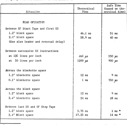
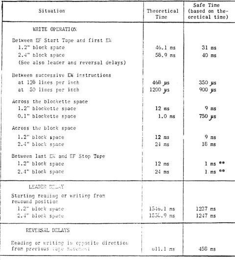
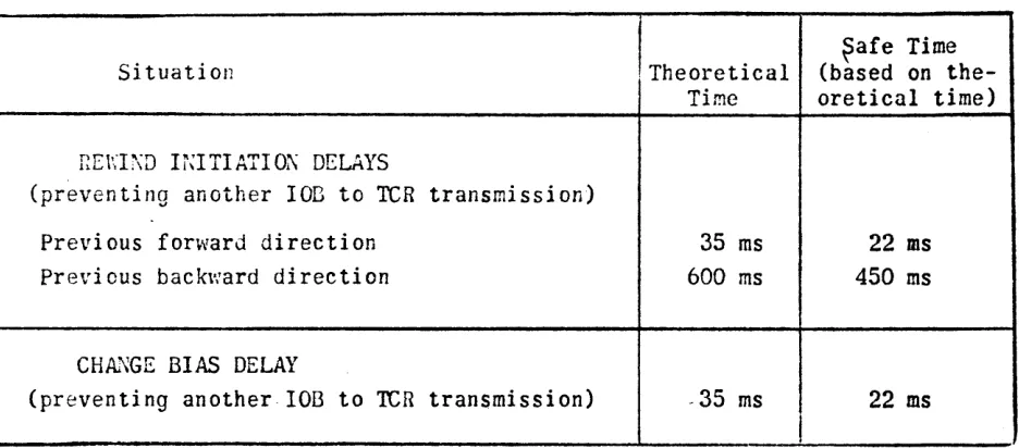
f) The 1103A Magnetic Tape System, 1105 Bypass Mode
I. Fixed Bleck Length
A) Representation of Data
.n
TapeB) Tape Format
C) Registers ef the Magnetic Tape Control Unit
D) Selectien of Magnetic Tape Operations E) Discussion of Mgdes of Operation F) Checks made during "Read- Operations
G) Most Frequent Programmin~ Faults B) Miscellaneous
J) Saople Prograns
II. Variable Block Length
Page 57 57 57
58 59 60 61 62 63
A) Data Repres.entation and Tape Format 64
B) ''\'iri te" Operation 64
C) "Read" Operation 64
1) End of Block Detection 65
2) Parity Error 65
3) hlGd 6 Error 66
4) Parity and Mod 6 Error 66
5) End of Recerd Detection 66
6) Su~~ary 66
Flew Chart for Read Operation 67
D) Stop Tape Operation 6e
E) Move Forward (or Backward) . 68
F) Rewind, Rewind with Interlock. Change Bias 68
G) Selection ef Variable or Continuous Input ~lc.de 68
H) S~~ple Progra~s 69
J) Continuous Data Input 70
III. Tape Format Required by Off-Line High Speed Printer 70 b
VI) The 1105 Magnetic Tape And Buffer System
A) General Introduction to the 1105 Buffer System 71
B) Physical Structure of the Buffer System 71 C) Information Flow via Buffers
l) Computer ~ Buffer 72
2) Buffer ~ Tape 73
D) Buffer States 1) 1LoadM
and ·Unload- 73
2) Buffer "Activity· 75
E) Programming for Write Operations Using Buffers
~) Fixed Block Length 76
j) Variable Block Length 76
F) PrGgr~~ing fer Read Operations Using Buffers
~) Fixed Block Length 77
)7)
Variable Block Length 79G) Stop after Read or Write Operatiens 80
H) Selectien of Bypass Buffer Mode 80
') Automatic Tape Centreller 81
K) Some Timing 82
L) Faults 83
VII) The lI03A and 110S Interrupt Feature
A) General Explanation
B) ~odification of the Computer Program by an Interrupt Signal and Programming Consequences
1) then Joes the Interrupt beco::Je effective? 2) ~oJification of ~p 6 by the Interrupt Signal 3) Progra~Tiing Consequences
C) The Program Controlled Interrupt 1) The ItBull" Card Un i t
2) The 1105 Buffe~ System 3) Other Equipments
VIII) The 1103A/II05 Floating Poi~t System
A) ~·~epres011tatioIi. of i\unbers B) Floating Poir.t Co:nmands
C) Some Remarks on r~lachi ne Cpera ti OilS Occurri ng
During Floating Point Arithmetic Processes
0) Use of "Transmit" and "Compare" Instructions for Floating Point Numbers
APP=~~DIX Table Table Table Table Table Table Table Table
Special ::emarks Oli the Buffer Systen
I:
II:
Ill: IF .
.
.
V: VI: VII: VIII:
~eaJ Single CarJs
r:eaJ Consecutive Cards, Single Card kode
;~eacl Consecuti ve Cards, Free fiun Punch .3ingle Carus
PUl~Cr. Cor.secuti ve Canis, Single Card j\;ode Punch Consecutive Cards, Free Run
~eaJ dn~ Punch Simultaneously, Single Cards
Bit f.ssig!~ments for I~:agnetic Tape Operations of the 1103~/110j anJ for Buffer Operations of the 1105
Page r.r-()J 05 66 87 86 C9 90 91 93 98 96
I) The 1103A/1105 Address System
a) Ma91leti~CorJt ,§toz:!9!
The core storage of the 1103A and the 1105 computers consists of up to three (3) banks of cores. One bank of core storage
holds 409610 36-bit-words and is a standard equipment.
The addresses are: &~S 0 (first bank): MCS 1 (second bank): MCS 2 (third bank):
b) Arithmetlc_R~ister.!
00000 thru 07777 (octal) 10000 thru 17777 (octal) 20000 thru 27777 (octal)
The addresses of the 36-bit Q-register are:
31000 thru 31777 (octal)
The addresses of the 72-bit Accumulator are:
32000 thru 37777 (octal)
c) .Masneti,.g Dr!!!Il..?~!2~ ("Double Drum")
The magnetic drum storage is divided into two (2)~; zone A and zone
B.
Each zone possesses 1638410 registers with addresses40000 thru 77777 (octal)
Therefore we have 2 registers 40000, 2 registers 40001, etc. If
e.g. a reference to 40000 is made it depends upon the zone -selection made earlier, whether "40000 zone Aft or "40000 zone B"
is employed. This zone selection will be described later. (See page 50.)
d) .!lle.9,.al. !.dQrELSl.e~
The illegal addresses of the computer are, if it is equipped with one bank of core storage: 10000 thru 30777 (octal) two banks of core storage: 20000 thru 30777 (octal) Three banks of core storage:
II) The Program Address Counter PAK
a) ~'!.e!.a!.. ~el!a!k.!
30000 thru 30777 (octal)
PAK is a l5-bit register which serves in two ways:
1) as a storage for the address from which the next command is to be extracted.
The extraction of a command from storage and its execution is based upon eight (8) ~iain Pulses, MP 6, ~lP 7, and MP 0 thru r\lP 5.
:.IP 6 and r,lP 7 extract a command from storage,
fllP 0 thru rolP 5 execute this command.
A computer Master Clear which precedes all operations of the computer sets it automatically to rJP 6 and PAK to 40000. Before depressing the Start button the operator has to manually insert the-address at which the program starts, into PAK (if this address is different from 400000).
Now the following sequence of steps takes place upon starting operation: (It is pointed out that one box of the flow diagram does not represent one
clock pulse)
1
Clear PCR1---Initiate Read: Clear
X
Wait Int. nef.MP 6
- - - -
--
---T
MP 7
~
_____ 1 __ _
hlP 6 essentially transfers the address from PAK to Sfu1, advances PAK by 1, and reads the word from the storage register whose address is now held in SAR, into X.
from
MP 7 brings the word X into PCR, where it later will be interpreted as command.
MP 7 also clears SAR, since this will be used during the execution of the command.
SAR
=
Storage Address Register, a 15-bit register. When reading from or writing into a storage location the computer "looks" at SAR in order to determine the address of this storage location. Notice that·SAR is not cleared, before the transfer PAl( to SAIl is made. However,each "Read into X" and "Write from X" sequence clears SAH immediately, after it used it. This involves transmissions between X on one side and core, drum, A, and Q on the other side.
But notice; after a "Shift" sequence SAR is not cleared. This is the reason for some rather unexpected results during special uses of ItLe ft Shi ft" and "Spl it" commands, as explai ned later.
-2-PCR
=
Program Control Register, a 36-bit register. A word entering PCR is interpreted as command. PeR consists of:~.lCR
=
Main Control Register; 6 leftmost bits of PCRwhich hold the operation code.
UAK
=
U-Address Counter; 15 bits holding the u-address portion of the command.VP~
=
V-Address Counter; 15 bits holding the v-address portion of the command .. Special use of UAK and VAK is explained later during the discussion of a command, whenever it is necessary.
b) Restrictions for Carries in PAK
When PAK is advanced a "1" is added to the number (address) held in PAK. The carry from one stage of PAK to the next stage is, however, restricted in the following way:
PAK
=
xxx xxx xxx xxx xxx (binary)PA~J.ri
JAKll
JAKo
PAK13 PAK12
Restriction present with all 1103A/liOS computers: There is never a carry from PAK13 to PAK14"
In addition to this the following restriction is imposed on PAK:
1) Computer with one bank of core storage If PAKl 4
=
0, there will be no carry from PAKli to PAKI2.If PAKl4
=
1, there will be a carry from PAKII to PAKI2•Consequences for a computer with one bank of core storage: Assume PAK
=
100 000 000 000 0002=
400008Here PAK can be advanced up to
III III III III 1112
=
177178,Lecause the carry from PAK11 to PAK12 can be made.
-3-Advancing PAK again by 1 we have:
III III III III III
+ 1 (binary)
100 000 000 000 000 That means that in PAK
771778
+ 1
40000 8
(octal)
Assume PAl(
=
000 000 000 000 0002=
000008Here PAK can be advanced to
000 III III III
1112=
071718
Because of PAK14
=
0 there will be no carry from PAKII to PAKI2. T~ereforet adding a"1" again we have:
000
III III III III
+ 1
000 000 000 000 000 That means that now in PAK
07777
+
100000
(binary)
(octal)
2) Computer with two or three banks of core storage.
In this case the restriction mentioned under 1) depends upon a switch set on the Supervisory Control Console. This is the so-called MCS-Section Switch. It will be set to one of the following two positions:
SINGLE - If "the switch is set to this position the restriction for the carry is imposed on PAK as discussed under 1) above, i.e. there will be no carry from PAKll to PAKI2, if PAK14
=
o.
NOR~~ - Setting the switch to this position means to drop the restriction mentioned under 1). That means that now a carry from PAKII to PAK12 can be made
-4-regardless of the value of PAK14. (Only exception: see "Repeat Command").
Let us look at the Normal setting of the switch. Here the programmer has to keep in mind the following fact:
a) Computer with 1!Q banks of core storage: PAK can be advanced from OOOOOs thru 177778. But 177778
+ 1
results in PAK =000008_
b) Computer with ~ banks of core storage: PAK can be advanced from 000008 thru 277778•
But
277na
+ 1 resul ts in PAK
=
OOOOOa
(In order to find out ~ this is accomplished by the machine re~er to Block Diagrams)
III) Remarks on "One's Transmission"
Experience shows that some confusion exists even among experienced programmers of the 1103/II03A/II05, if the word "one's transmission" is mentioned. However. as pointed out during the discussion of PAK (see: PAK~SAR), it is absolutely necessary that a programmer understands the meaning of this word and the results caused by a one's transmission, if he really wants to understand the Shift-and Split-Commands (which will be discussed later in details).
Without going into engineering details let us consider the final results after a one's transmission from PAK to SAR:
Here One's Transmission means:
If PAKi
=
1, swi tch SARi to "1 '\ If PA~=i=
0, do not touch SARi.(i
=
1,2, •••••••• 14)Assume PAK
=
000 110 100 010 0112=
064238 After one'sJ
SAR=
011 001 011 110 0102=
313626 transmission SAR=
011 III 111 110 011 2=
377638This result can easily be obtained applying the above rule.
The example also shows that the result may be obtained by applying the following logical addition in binary:
-5-0+0=0
o
+ I=
II + 0 = I 1 + 1
=
1This means that you merely may add the two numbers in binary in the normal way with the exception that I + I
=
1. No carry will be produced.It should be noticed that all transfers as e.g. storage--+X, X~storage, X~Q. etc. are made by one's transmission. However, in order to obtain
the correct result in the register into which has to be written the computer automatically clears this register first. Thus, if e.g.
(X)
=
0--0100(v)
=
1--1100and (X) --;. v has to occur. the computer produces.
Clear v.
One's Transmission from X to v.
This is merely stated here. The only exception from this general rule which is the concern of the programmer is the above mentioned one's transmission from PAK (OAK, VAK) to SAR or SAR to PAK.
IV) Special Discussion of Basic 1103A/Il05 Commands
The following paragraphs represent a discussion of all commands except Floating-Point-Commands and the Input/Output-commands EF -v, ER jv, EW jv. This discussion refers in particular to programming situations which either would cause a computer fault or an unusual result; it requires. however, a basic knowledge of these commands on the part of the reader.
During most of the commands numbers are transferred in the computer from
storage to storage storage to A or Q
A or Q to storage
plus certain transfers to input/output registers (discussed later). All these transfers are made via the X-register (Exchange Register).
-6-Two of the above transfers are of special interest: Accumulator to.X, X to Accumulator. These are transfers between a 72-bit register and a 36-bit register requiring special discussion.
1) Accumulator to X:
With the exception of one command, the LT jk v, there will always be a transfer of (A
R) to X. This is done automatically by the computer. Thus, the computer never picks up (AL)
except in a LT jk v with j
=
O.2) X to Accumulator:
Here the situation is somewhat different. A is an additive register which means that a number may be added to (A), but not transferred to A. If a transfer is to be obtained the computer automatically executes the following steps:
Clear A
(A) + D(X)
--+
AThis results in the double extension of (X) in A, i.e. (A
R)
=
X and (AL) contains sign-bits.However, some commands so not use the double extension.
These are the three (3) Q-Controlled commands and the four (4)
Split-commands. They use the single extension S{X), i.e. (AR)
=
X and (AL) contains zeros.Keep in mind that the Q-Controlled and Split commands are the only ones which make use of SeX) instead of D(X). All other commands always use D(X), if (X) has to be added to (A).
b) "Transmi t" Commands TP u v
TM u v
TN u v
Sequence: (u) ~ X • (X) ~ v ••
•• If v = A: Clear A
(A) + D(X)~A
• If u
=
A: {AR)-+XThese two commands are executed like the TP except that
I
(u)1 or (u)l, respectively, are transferred-7-Notice that no faults ever occur during the execution of one of these three commands because of the use of A or Q as u- or v-addresses. (Here, and from now on, it is assumed that no illegal addresses like 300008 etc. are used as u or v. The use of an illegal u- or v-address, naturally, results in an SCC-Fault, SCC being Storage Class Control.)
TO
u v
Sequence:u29 ••••• ulS -4 X29 ••••• XIS
129 •••••
Xis
-+ v29 ···vISTo write it in a different way:
(u)
--+
vu u
Keep in mind:
v3S ••••• v30 and vl4 ••••• vo remain undisturbed
If u
=
Aiu
=
Q;However, v
=
A Q! Q results in an seC-Fault.TV u v Sequence:
u14 •••••
Uo
-+ 114 ••••• XOXl4 ••••• XO ~ Yl4 ••••• vO
or, written in a different way:
(u)y ---+ Y v
Again, v3S ••••• vIS remain undisturbed
If u = A: (Aa>v - t Vv
u
=
Q: (Q>v ~ VvLike in the TU u v v
=
A Qr Q results in an SCC-Fault. Therefore keep the general rule in mind:It is not possible to transfer parts of a 36-bit number into A or Q.
-8-c) "Ari thmeti c tI Commands
RA u v Sequence:
(u)--7X Clear A
(A) + O(X) -7 A
(v)~X
(A) + O(X)~A (AR)-J X
(X) - 7 u
*
• omi t , i f u
=
AIf v
=
A the above sequence shows that then (u)f=
2 • (u)iprovided that no "overflow" into the sign position (bit i3S) occured during the addition.
RS u v
If v
=
A: (u)f=
0 (A)f=
0The sequence of this command is equal to that of the RA u v except that (v) is subtracted from (u).
AT u v Sequence:
5T u v
(u) -+ X
(A) + O{X) ~ A (AR)-7 X
(X)-+ v ~
• omi t , i f v
=
AThe sequence is equal to that of AT u v except that D{u) is subtracted from (A).
Notice that the above four commands RA, RS,AT, and 5T never result in a computer fault. An "overflow" into the sign position i35 occuring during an addition or subtraction will, therefore, not be noticed during machine operations. If the programmer suspects such a possibility for an overflow he may e.g. apply the method suggested in the following paragraph:
-9-Assume (u)i
=
0 1 - - - - 1(v)i.= 0 01
(binary) (binary) The command RA u v results in the following:
D(u)
--+
A: (A)=
0 - - - 001 1D(v)
=
0 000 - - 01+
(AR) ~ u: (u)f
=
10---0f
(binary)
(binary)
As it can be seen: The sum of the largest positive number in u, (u)i
=
235 -I, and a "I" results in a negative number in u, (u)f =~(235 -I), which is the negative number with the largest absolute value.Assume the command following the RA u v is an EJ u w~ This will test whether or not D(u) is equal to (A). In the above case this equality would not occur.
Therefore: Whenever the programmer suspects an overflow during an addition he may test this by giving the following commands:
a RA u v a+l EJ u w a+2
Upon jumping to w the programmer knows that !!.Q overflow occured. But if the computer proceeds with the next
instruction in sequence (e.g. at a+2 in the above example) the programmer can provide some means which will indicate to him that an overflow occured.
MP u v Sequence: (u~X Clear A
(X)-+ Q (v)-+ X
Form in A the (true) product of (Q) and (X).
Giving this command the programmer has to keep in ~ind two things:
(Q). is destroyed and replaced by (u)
Moreover: if if
It is obvious overflm\' into
MA u v
v = A: (A)f
=
02
v
=
Q: (A)=
f (u)-1
that this command never results in an the sign-position
Sequence: (u)~X (X)~ Q
A71-Shift (A) left 36 places
{v)....-+ X
Add the product (Q) • (X) to (A) using
an addition process.
This command results, as it is well known, in {A)f
=
(A)i+
(u)·{v). However, during the addition an overflow intothe sign-position might occur depending upon the values of (A)i' (u), and (v). The overflow might occur, if (A)i is very large such that A71
¥
A70• The computer tests this condition cfter the above shift of 36 places in A has been made, i.e. it tests, whether or not A35¥
A34. If this is the case computation stops with an Overflow-Fault ("Att-Fault) indicating the possibility of an overflow.Notice that A35
¥
A34 or. originally, A71 # A70 does ~mean that an overflow will occur in any case.
DV u v Sequence:
(u)~ X
(A) .
(X)l ~ Q
(Q)~ v
*
(A)f ~ 0 is Remainder c: I f v=
A:Clear A
(A) + D{Q)~A,
i.e. remainder is lost.
Notice that the remainder in A always is positive. This can cause differnt results in Q and A during two divisions performed with the same arithmetic number.
-11-To illustrate this let us take the number - ~.
First case:
Second case:
{A)i
=
+ 7 (u)i= -
3here:_ 37
=
.2 + 1--3Therefore:
<A).
=
-71
<u)· 1
=
+3here: -7
=
3
Therefore:
quotient <Q>f
=
-2remainder <A)f
=
+12
-3 +-3
quotient <Q)f
=
-3 remainder (A)f=
+2It is clear that the quotient of a division might consist of more than 35 significant bits, as e.g.
(A)i
=
260 , (u)=
22, quotient = 256Such a number cannot be placed into Q. Therefore, if this situation occurs, i.e. an "overflow" in Q is about to take place, the computer stops with a Divide Fault ("A" Fault).
Notice that at this time (A)i will be already destroyed.
d) Jump and Stop Commands
--
-~ -~
-
.-.--~~-The following commands. cause the computer to "ask the question"
EJ u v Is D(u)
=
(A)?TJ u v Is D(u)
>
(A)?ZJ u v IS (A)
=
0 ?SJ u v Is (A) :>
o
?QJ u v Is (Q)
=
o
?*
If the answer to any of the above questions is "yes" a jump to address v occurs.
If the answer turns out to be "no" the sequence of steps which has to follow depends upon the nature of the command:
One-way-jump (EJ, TJ): take next instruction in sequence Two-way-jump (SJ,ZJ,QJ): jump to u.
The above commands do not alter the contents of registers involved in their execution.
IJ u v Sequence:
(u)~ X
Clear A
(A)
+
D(X)~ A(A) -1 ... A
Is A71 = 01 If yes:
(AR)f ~ u
jump to v If no:
take next instruction in sequence
The reader will probably know that this command is mainly used for performing "loops" in the program, i.e. for executing a part of a program several times. Keep in mind that, if a part of the program has to be executed n times and theIJ is at the end of this part (where it will be in almost all cases), the "index"
(u>
has to be=
n-l.Also notice: after the loop has been performed n times and the computer continues with the instruction immediately following the IJ, (u)f
=
O.MJ j v
The sequence of steps resulting from the execution of this command depends upon the value "j". Thi s j is represented by the leftmost octal digit of the u-portion of the command, exactly i29 i28 i27 in binary. Let us discuss the different values for j:
j
=
0, i.e. MJ 00000 vj
=
1, i.e. MJ 10000 vj
=
2, i.e. MJ 20000 v j=
3, i.e. MJ 30000 v
-13-This is an unconditional
j ulip to address v.
Either the switch on the console which corresponds to the number used in the command (1,2, or 3) is set
then: undonditional jump to v or the corresponding switch is not set
then: take next instruction in sequence.
Keep in mind: the above mentioned switch on the console can be set or released, if and only if the computer is ~ operating. During computer operation a setting or releasing of these switches is blocked.
Therefore: if one part of your program makes use of a j
=
1 set, and another part requires j=
1 to be released then you have to stop computer operation with a MS jv(see below). Now the switch may he released, and operation can be resumed.
j
=
4, i.e. MJ 40000 vj
=
5, i. e • MJ 50000 v j=
6, i.e. MJ 60000 vj
=
7, i.e. MJ 70000 vThese values of j do not possess any corresponding switch on the console. The execution of these four (4) commands has to be discussed for two cases:
1) ll03A, i.e. computer without Buffer System: Here the j is actually determined by the bits i28 i27 which means that i29 is disregarded by the machine. Therefore, we have the following situation: If i29 i 28 i27 equals it results in a "machi ne j"
000 or 100. j
=
0001 or 101 j
=
1010 or 110 j
=
2011 or III j
=
3As you can see: a MJ 00000 v is equivalent to a
MJ 40000 v, •••••• , a MJ 30000 v is equivalent to a
MJ 70000 v.
2) 1105, i.e. computer with Buffer System:
of
In this case any MJ jv with a j of 4,5,6 or 7 represents a completely different kind of command used for Buffer
operations. This will be discussed under "Buffer System".
-14-The following remarks refer to all jump commands: If v
=
A and a jump to v occurs: See-Fault For two-way-jumps in addition:If u
= A
and a jump to u occurs: SeC-FaultNotice that the fault occurs, if and only if a jump to A is made, i.e. if the programmer tries to extract the next
instruction from A. However, the command EJ u A with (A)
=
0,(u)
=
1 will, for instance, not result in a fault.Notice: If a
3umP
to Q is made in any jump-command a fault is ~ generated. The machine will pick up(Q>,
send it to PCR. and interpret this as command. The programmer will certainly never try to jump to Q. If this, however, happens because of programming errors, there are three possibilities:(Q) contains an illegal operation code: MeT-Fault
<Q>
contains a jump command: Jump will be performed normally.<Q>
contains a legal, but not jump, command: This will bej
=
0:MS j v
v--+PAK Stop
executed. Since PAK is advanced, say from 31000 to 31001, the next command is again taken from (Q), etc. Notice: you might advance PAK, until it reads 32000. Then: see-Fault I
There exist again switches on the console for j
=
1, 2, 3.Notice: . v---+ PAK indicates: erase the address held in PAK, and replace it by v. Therefore, a "jump to address v" has been set up by the machine, but before continuing at v a stop is made.
j
=
1,2, or 3 and corresponding switch set: v~PAK Stopand corresponding swi tch
!!.2!
set: v ~ PAKAs you see: v-+ PAK, i.e. jump to v, takes place in any case. j controls stopping or not stopping only.
Refer to MJ j v in order to see the difference between that command and the ~5 j vI
-15-j = 4,5,6,7: For ~ computers, 1103A and the 1105, these values of j correspond to the values 0,1,2,3 in such a way that a j = 4 results in a "machine-j tt of 0
a j = 5 resul ts in a "machine-j tt of 1
a j = 6 resul ts in a !!machine-j r: of 2
a j = 7 results in a "machine-j" of 3
PS
-This is the Program Stop command. If this command is given computer operation can be resumed after a computer Master Clear only.
Two commands are used for referencing subroutines. These are
the Return Jump RJ u v and the Interpret IP - -.
RJ u v Sequence:
PAK~X14 ••••• XO
Clear PAl(
v--.PAK
The sequence for this command is given here in details in order to
inform you about the real facts, sinee the explanation to be found
usually might cause confusion on the part of the reader or might
mislead him. This incorrect explantion I refer to is:
If Y is the address of the RJ uv t then y
+
1 ~ UVt v ~PAKTo state it again: this last mentioned explanation of the RJ uv
is incorrect.
Let us follow the correct sequence with Assume you have the following program:
At the very beginning of the execution PAK
=
00171 (since it is advanced PeR=
RJ 00170 00150an example:
Start oof50 RA 01900 02000
r
OOi70 RJ 00170 00150 00171 --
----of the RJ uv you have: by 1 already)
placing it into X, erases PAK, and continues with: 00150--7 PAK (X)v
=
OOl7l~ool70vThus the RJ at 00170 is now modified and reads RJ 00170 00171
and a jump back to 00150 is made. If the RJ at 00170 is executed again later (and has not been changed by some other means in the meantime) it will not jump you back to 00150 again, but you will proceed with the next instruction in sequence. As it can be seen: the explanation y + l~ Uv would mean
that 00171 is sent to 00l70v changing the RJ before the jump is initiated. According to this explanation you had to pick up 00171 and to place it into PAK (by v --7 PAK). Thi sis not
the case.
You might, however, say: at least the explantion is correct as far as y ~ 1 is concerned, because the above example picks up 00171, and this is y + 1.
This is right in the above case and will always be so as long a$ no Interrupt Signal is generated because of the use of the Interrupt Feature, However, if a RJ is executed right after the generation of an Interrupt Signal it will pick up the address held in PAK which will not be the above mentioned
y + 1. (See under "Interrupt Feature") Thus keep in mind:
Executing a RJ u v means to place the address held in FAK at that time into Xv, placing v into PAK and, finally, (X)v into
Uv·
Usually the Return Jump is not used in:the way as described in the above example. Normally the v-address of the RJ u v denotes the entrance of a subroutine, and the u-address denotes the exit of this subroutine, where e.g. (u)
=
MJ 00000 30000. Keep in mind: using the RJ u v means that the entrance and exit of the subroutine referenced may be an)~here in the core or drum.As already discussed earlier an See-Fault occurs in the following cases:
If v
=
A: See-Fault (do not jump to A)If u
=
A Q!' Q: seC-Fault (do not try to write parts of a 36-bit number into A or Q)For v
=
Q refer to tht:: explanation given under "Jump and Stop Comma nds".IP
The ten (10) octal digits which form the u-and v-portion of the IP-cornmand are insignificant. They.are completely disregarded by the machine during the execution of the
IP --.
The sequence of steps which takes place can briefly be described as follows:
PAK-t v-porti on of F 1
F2
=
00001 ~ PAKAddress Fl is determined by a switch on the Supervisory Control Console which can be set either to
"ooooott
or "40001". Its normalsetting is "00000" (also refer to "Repeat Command
tt
which uses the F l-Swi tch).Assume Fl
=
00000. In this ease the address held in PAK at the beginning of the execution of IP (which will be=
address of IP-command + 1 in almost all eases; see remarks under RJ uv) is transferred to the v-portion of the content of 00000, and a jump to F2=
00001 is initiated. Thus the IP referenced a subroutine whose entrance is 00001, exit 00000.If Fl = 40001 keep in mind that now the entrance is again F2=OOOOl, but the exit of the subroutine will be 4000[~.
The usefulness of this command is based on the fact that the ten octal digits of its u-and v-portion may be used for storing other information as e.g. parameters, pseu~o-codes, addresses, etc. which may be used by the subroutine to which the IP ~- refers (Interpretive System) •
f) The "Left Shift" Commands
...
.-..
--.-,~-
...
.-.-As you know shifting can be performed in two registers: in the Accumulator and in the Q-register. There is only a shift to the left. Moreover in either register we have the so-called "end around shift''. i.e. you do.!!..21 "drop off" bits at the left end of the registers. The two "Left Shift
tt
commands are LA u k and LQ u k. Tbe v-portion of either cormnand contains a number k which determines how many places a word in A or Q is to be shifted to the left. Do not forget: a binary word is shifted by the computer, i.e. k refers to '~inary places".-18-Example:
Assume (Q)i = 0---01001 in binary. k = 4. After shifting has been performed (Q}f is:
<Q)f
=
O. 010010000 in binary. Let us examine the sequence of the LA u k:(U)~X}
omit, if u
=
A Clear A(A) + D(X) ~A
Shift (A) k places left {AR)f -; r
where address r is given by the Boolean logical sum of (u) + (v-k)
v denoting the v-portion of the LA u k.
The first part of the execution of this command is probably well known to you: take the double-extension of (u) place it into A,
and shift k places left. (If u
=
A, just shift (A)i). But now comes a point which has to be discussed in details, because the steps to follow depend entirely upon the number contained in the v-part of the instruction LA u k. This v-part consists of 1510 bits. However, just 7 bits are used for the representation of the number k, as indicated below::v-part of LA uk: xxx xxx ~ xxx xxx
~.~
8 bi ts : k
How does the machine determine how many p_laces it has to shift? This is done in the following way:
After D(u) is in A1 the v-part of the LA u k is transferred to
t.
SAR (from VAK). The rightmost 7 bits of SAR are used as a Shift-Counter, SK, and the machine performs the sequence:
Is SK
=
0 000 OOO? (binary)If ~: Shift (A)~~ place, subtract one from SK, and go back to above question. If yes~ continue with the following steps:
---- Transfer the u-address (from UAK) by
As you can see: the transmission of u to SAR will result in SAR
=
u, if the leftmost 8 bits (as shown above) were all zeros. If they are not all zeros, you generate the Boolean logical sum (" 1 + 1=
Itt) in SAR between u and what was left in SAR at the end of the shifting. This might generate an address completely different from u.Let us follow three examples:
1) Shift (01050) 1710 places and place (AR)f back into 01050. Here: LA 01050 00021
~
v-part of LA-command
Before the shifting of D(01050) in A takes place 000218 ~ SAR.
Therefore, _SAR
=
000 000 OO~ OO,!k
(binary>
After the shift SAR
=
OOOOOs. The transfer u=
0105Qa to SAR results in SAR =.0105°8, and thus (Afl>f ~back to Ol050.2) Shift (01050) 1710 places in A and send result to 05250. Here we will use the command LA 01050 ~
v-part I
Before the shifting
SAR
=
000 101 OLQ..~ OO.Jk
(binary)
After the shift of 1710 places (notice that k
=
218=
1710) we have:SAR = 000 101 010 000 000 (binary)
The one's transmission 01050a -+SAR results .in the following: + (one's transmission) 000 101 010000000 (binary)
000 001 000 101 000 (binary) 000 101 010 101 000 (binary)
or 0 5 2 5 0 (octal)
Therefore, we now send the answer~(AR)f to 0525°8_ as intended. Notice that you always have to carefully figure out the v-part of the LA-command, if you wish to send the answer to a register different from u·. Also notice that this register must have an address which has to be at least larger than u by 200., In fact, it has to be larger by n· 20Da than U, n
=
I, 1, 2, 3, •.•••••-20-3) Shift (01050) 1710 places in A and leave the answer in A.
Here the command LA OlOSO 32021 will give us the desired result, because
SAR after the shift
=
011 010 000 000 000/.u
=
OlOSOa=
000 001 000 101 000 011 011 000 101 000As you see SAR
=
330SQa which denotes A.(binary) (binary) (binary)
Notice that !nI core-register may be used for this purpose, i.e. for shifting in A and leaving the answer in A. (Compare this with the remarks made on the
LQ
u k for leaving the answer in Q. See below).Generally speaking the above mentioned address r can be easily found by subtracting at first k from the number which makes up the v-part of the LA u k. Then address u has to be added to this in binary such that 1+ 1
=
1. Doing so with the above examples we have:I) v
=
000218' k=
218, v - k=
000008. u ~ 010508. Therefore u + (v - k)=
010S08(T
logical sum, 1 + 1=
1)2) v = 052218, k = 218,
v -
k=
OS 2008 ,u
= 01OS08•Therefore u + (v - k): 000 001 000 101 000 2
+
000 101 010 000 0002
000 101 010 101 0002
u + (v - k)
=
05250e(flogical sum, 1
+
1 = 1)3) v
=
320218. k=
218' v - k=
320008, u=
01050a. Therefore· u + (v - k)=
330SQs=
A(t
logical sum, 1+ 1
=
1)The
LQ
uk instruction works in the same way with the exception that u is now placed into Q and shifted there. Again SAR is used like in the LA u k. Thus you can send results to registers different from u.-21-There is only one situation which requires special discussion. This is the case that you wish to shift a number in Q and leave it there.
You have seen that you may use any core-address in order to shift a number in A and ieave the resuit there. IOU will do that by
giving a LA u 32000
+
k command, as e.g.· LA 01050 32021. This may give you the idea that you may do the same with aLQ
u k command, i.e. may try to shift (02000) in Q and leave the result in Q bygiving a
LQ
02000 31003 (shift 3 places). This, however, is ~ true. The result will be sent to A (that it also stays in Q is beyond any doubt). The reason is thatu'
SAR after shift
000 010 000 000 0002
+ (one's transmission) 011 001 000 000 0002
011 011 000 000 0002
results in 3300Qa in SAR which is the address of A.
It can easily be seen that the following addresses may be used in order to leave the result in Q without sending it to any other place:
00000 thru 01777 10000 thru 11777 20000 thru 21777
(octal) (octal) (octal) No other addresses will accomplish this.
g) The "Left Transmit" Command
--
- -
-.-
~--
-. ~ .-.-As it was said earlier: the computer always pieksup (AR), if a number has to be obtained from
A.
There is only one command which takes the content of AL provided that the programmer specifies this. It is the LT jk v.·Sequence:
Shift (A)i k places left If j
=
1: (AR)f--+X If j = 0: (AL)f---+ X In either ease:(X) --+v
*
• if v
=
A: Clear A(A) + D(X)~A The u-portion of the command contains the number jk, such that
~.xxx~
j
-22-As you see: the rightmost 7 bits of the u-portion denote' the number k, but
2112
bit is used for determining j. All other bits are disregarded by the machine during the execution of the LT-command. They also do ~ affect the LT itself or the sequence of steps to follow, if theyare different from zeros.
The j is, programwise, given by the leftmost octal digit of the u-portion of the LT jk v. Therefore:
0=000 2 1 = 0012
all result
2
=
0102 3 = 0112 result in a4 = 1002 "machine -in a j" 5 = 1012 "machine - j"
6 = 1102 of "0" 7 = 1112 of "1 t. This means:
j is an even digi t: (AL) --? X j is an odd digi t: (AR) --+ X
This decision "even or odd" is made by the machine such that it "examines" the bit UAK12 (do not forget: during its execution the LT is in PeR).
h) !he "~PJ.!.t: ~o~!n;J~
All four split commands have in common that the single-extension of a number is added to (or subtracted from)-A.
SP u k Sequence:
(u) -+X
Clear A
(A)
+
S(X)~AShift (A) k places left
The number k denoting the number of places (A) has to be shifted is, as in the LA-and LQ-commandst given by the rightmost 7 bits of the v-porti on of the SP u k ·couunand. The remaining 8 bi ts of this v-part are insignificant for the execution of this and the other 3 split commands. They, however, affect the sequence which follows with the next MP 6 (see under "Program Address Counter"). This requires a detailed discussion.
-23-The question is: what is left in SM, after the shifting of k places has been made? Obviously SAR will contain all zeros in the rightmost
7 bits, but the leftmost 8 bits will be equal to those stated in the v-part of the SP u k. Example:
Here. k
=
5. Thus, after the shift we haveSAR
=
000 010 l~ (binary)SK, now
=
0It is important to understand that SAR is not cleared at the end of the SP u k_ The computer proceeds with the normal MP 6 (see page 2). That means: PAl< - ? SAR by one 1 s transmi s s ion. If, as gl ven above
in the example, the SP-command is stored at address 052028. then PAK contains 052038 _ Let us see what number is generated in SAR by
PAl{ ~·SAR:
SAR
=
000 010 100 000 000PAl{
=
000 101 010 000 011 final SAR=
000 111 110 000 011(binary) (binary) (binary)
As MP 6 and MP 7 state: the next command is to be extracted from the location )lihose address is held in SAIL This is now 076038 _ At the same time PAK holds the address 052048 ·since it was advanced by "1 ". Therefore we do the following:
At first the SP at 052028 is executed normally. The next instruction is extracted from 076038. If this is not
a
jump we proceed at 052048• As you see: only 052038 has been omitted I Naturally, if the v-part of the SP-command contains the number k only (i.e., the leftmosta
bits of the v-portion are all zeros), SAR will be equal to "zero" after the shift, and we will proceed in sequence. This is the normal way of using the SP-command.It is pointed out that you may not arrange the v-pan' su~h·that the next instruction had to be taken from A or Q. If you do so, you get an seC-Fault in case the address of the accumulator results from
PAK~ SAR. If you end up wi th Q. no fault will be generated. However, the steps to follow depend upon the content of this arithmetic register!
-24-All following three split commands use SAR in the same way as the SP u k. The sequence following the shifting is, therefore, equal to that discussed for the SP-command.
In general one can say for
!l!
split commands:The instruction following the split command is extracted from location PAl( + (v - k)
(1
Boolean logical sum, 1 + 1=
1)where v denotes the 5 octal digits which make up the v-portion of the split command.
SA u k
SN u k
Sequence: (u) --+X
(A)
+
SeX) ~AShift (A) k places left
Sequence: (u) ~X Clear A
(A) - SeX) ~A
Shift (A) k places left
This can also be denoted as
(S(x>] 1 -+A
Shift(A) k places left but the explanation found sometimes which says
S(X)l ~A etc. is completely wrong. Reason:
Assume (X)
=
7 76 (octal). Then:SeX)
=
0 0 7 - 7 6[S(X~11
=
7 7 0--01but (X)
=
0 - 0 1 S(X)1=
0 0 0 - 0 1Notice the difference between [sex)] 1 and S(X)I.
SS u k Sequence:
(u)~X
(A)-S(X)~A Shift (A) k places
-25-A final evaluation of all four sequences shows: The difference between SA and SP is:
in the SA the step "Clear Aft is omitted. The difference between SS and SN is:
Otherwise the command itself points out (Split Positive Entry. Split.Subtract, etc.) whether a single extension is added to or subtracted from A.
i) !!t~ t~-£ont~lled·f.OO!!la!!.d!
These commands are merely mentioned here without any discussion of details. There are just three things you have to keep in mind when you perform a ttmasking" operation:
1) The logical product L(Q)(u) is a bit-by-bit product, such that
o •
0=
0o ·
1=
0 1 0=
01 • 1
=
1This bit-by-bit product is a pure ·logical operation and may not be mixed up with a (true) product of two numbers.
2) If in any of the three "Q-Controlled" commands u or v is A or Q, then watch out. The result may be different from what you expect. Some examples are:
QT Q v
QA
Q
vQS u A
QS u Q QS Q A
QS Q Q
(A)f
=
seQ)(v)f
=
<Q)(A)f
=
(A)i + seQ)(V)f
=
(~)f(A)f
=
L(Q)(u)(Q)f
=
(Q)l + L(Q)(u)(A)f
=
seQ)(A)f
=
236 - 13) The logical product L(Q)(u) is developed in X. Then the single-extension of this· number is added to At SeX) + (A)i ~A.
Therefore, (AL) is e.g. zero (36 zeros in binary) at the erad of any QT-command. It is also zero at the end of any QS-command, regardless of <Q), (u), and (v).
-26-"
j) _The i.on,E'o..!..1e.!! Comp1e~nt":' C..Em.~n~
The CC u v makes use of An during its execution. It does not clear or use AL- J\L is undistvrbed bv the CC-command.
AR
is used to develop the logical sum of (u) and (v). This sum is developed such that 0 + 0 = 0, 0 + 1 = 1, 1 + 0=
I, 1 + 1 =o.
Remember 1 + 1
=
0 is different from the result of the Boolean logical sum. There we had 1 + 1=
1.The logical sum applied by the CC can also be denoted as ''hi t-by-bi t" sum without carries".
Example:
CC u A
k) !1!.e ":tR~e~"S~~<!
The Repeat Command, RP jn w, repeats the next instruction several times, modifying it after each execution as specified.
The u-portion of the "Repeat It command contains the number jo, where
n. is given by the 1210 rightmost bits and j by the next two bits. The leftmost bit of the u-portion is not used for the determination of j. It affects, however, the termination of the repeat sequence! This will be discussed later.
~~
Tj
nleftmost bit
n denotes the number which specifies, bow many times the next instruction is to be executed.
j denotes how the u- and v-part of the next instruction is to be modified after each execution.
j -00 - 2 do not modify NI (NI = next instruction) j =.01 2 modify v-part of NI
j = 10
2 modify u-part of NI
j = 112 " modify u- and v-part of NI.
As you see: nothing has been said so far about'the leftmost bit shown in the above picture!
The modification of NI is done by adding a "1".
Basically we have to distinguish between two cases: the NI is a jump-command,
Let us begin with the second case.
1) The repeated instruction is not a "jump" -command. An example is e.g. .RP 10100 w
TP 0500006000
(05000) ; O. Here registers 06000 thru 06077 wiii be cieared, since j
=
1, n=
10°8-In
order to understand, why this is so and what happens in the machine that might affect programming we have to examine the sequence of the RP-command. This is given below in flow chart format and assumes that the Repeat command is stored at address y:w--} v-portion
. of Fl
Address w is sent to the v-part of FI'
where Fl
=
00000 or 40001 as determined by the switch on console.The NI is sent to X. PAK which holds Y
+
1is now free for other operations.
PAK is. cleared and the "Repeat" Sequence initiated (the latter affects several flip-flops)
The u-part of the ijP jn w is sent to PAK. Then this is complemented •.
(The above example would give us: 101008 -7-PAK, PAK1
=
676n)The NI which was sent to X in step 2 is now placed into the Program Control Register and ready for execution.
SAR is cleared for later use.
At this point the execution of the Repeat command is terminated. Noti ce that we made proper use of w, and j n t and that we a 1 S 0 "told ,.
the machine to start with a Repeat sequence.
-28-The repetition of the instruction following the RP jn w is performed by the se',uence:
--....,. Advance PAK
Execute Instruction
Modify UAK and VAK accord-ing to j
This sequence shows, how the machine determines, whether or not the NI has been executed n times. As you "can see the carry from PAKII to PAK12 tells the machine this fact. If it occurs the NI is llQ1 executed anymore, but the so called '~ormal Repeat Termination Sequence" begins at
~.
(see later)**
If NI is an EJ or TJ and a jump occurs! (See be I O\\')Let us follow the above sequenee with the example
a RP 10003 a + 2 a+l TP 00005 06000 a+2 -- ---
---At first the address a+2 is sent to the v-portion of FlO Then the complement of 100038 is sent to PAK. so that now PAK
=
677748, andTP 00005 06000 -?PCR. Starting "at
0
we want to accomplish the following:TP 00005 06000 TP 00005 06001 TP 00005 06002
and resume operation at a+2. Will we do that?
At first we ad\'ance PAK: 67774
+ 1
67775
(octal)
There was no carry_ Therefore we execute TP 00005 06000, and then mOdify PCR such that now (PCR)
=
TP 00005 06001Advancing PAK again we have: 67775
+ 1 (octal)
61776
No carry; therefore TP 00005 06001 is executed and PeR modified to TP 00005 06002.
-29-Advancing PAK the third time we get: 6m6
+ I
67n7
(octal)
. Again there was no carry_
ke
execute TP 00005 06002 and modify FeR to TP 00005 06003.PAK is advanced again: 67777
+
I 70000(octal)
Here the carry from PAKII to PAK12 oCDHred. At this time we already executed the three TP-instructiens as we Intended to do. It is,
therefore, all right that we do not go on executing the TP 00005 06003 which is in PeR', but' go to
0.
Do not forget: PAK
=
700008 at this time. This will be important later, 'if special cases are discussedlYou can' see that the modificatiOft'of the TP was done in FeR, not in the storage-location a+l. Keep in mind that the content of the storage . register holding the instruction to be repeated is not changed.
So far we have talked about ·a carry from PAKII to PAKI2• This carry g,enerates the "End Repeat Signal" which terminates the repeat sequence at once. Here you will probably remember the restrictions for carries in PAK as described under "Program Address Counter". How do these restrictions affect the above mentioned carry which' is to terminate the repeat sequence?
Notice: the MCS-Section switch does .!!.2.laffect ~ as long as a "Repeat
Sequen~e" is being performed.
*
(See under "Program Address Counter").This~means that a carry from PAKll to PAK12 can be generated by the
machine, if and only if PAK14
=
1, regardless of~the number of core' banks. Therefore, a Repeat Sequence can be terminated only, if the number j was a 0,1,2, or 3. because the ~omplement of either of these four numbers results in a leftmost bit equal to "1".Keep in mind: j
=
4,5t6, or 7 results in~an unterminated Repeat Sequence.The modification of the NI, however, will be performed such that a j
=
4 equals a j=
0j
=
5 equals a j=
Ij
=
6 equals a j=
2j
=
7 equals a j=
3, because this is determined by the machine by "looking" at PAKl3 and PAK12.• To be precise: as long as the "End Repeat" flip-flop is "I".
-30-As it was mentioned earlier: the repeated instruction is in PeR and the modification takes place there. It means that UAK and VAK are modified according to j. Both, UAK and VAK are counters, and the question arises, \vhat restrictions for carries in these counters are established. The answer is:
UAK and VAK possess exactly the same restrictions for carries as PAK,
including everything mentioned about the ~~S-Section switch. The only difference is that during a Repeat Sequence and the MCS-Sect. switch in Normal, there will be a carry from UAK!1 to UAK
l2 and VAKIl to VAKl2 regardless of the value of UAKl4 or VAK14 , respectively, but no carry
from PAKIl to PAKl2 unless PAKl4
=
1.Let us folIo\\' 'some examples: (assuming 3 cores)
1) a RP a+l TP a+2
=--17000 a+2
12000 05000 (120oo)i
=
0 - 0First case: MeS-Section switch set to SINGLE:' Here we clear registers 05000 thru 07777
and 00000 thru 03777.
(v-part of TP is in VAK: VAK
=
0500Qe. Modifying this with the restriction that no carry from VAKIl to VAK12 occurs, gives us the above result.)Second case: MeS-Section switch set to NORMAL:
Now we clear registers 05000 thru 13777, i.e. 70008 _ consecutive
storages. (Carry in VAK is enabled by switch •. )
As you see: If the machine possesses two or three banks of core storage, and you use the Repeat command, then give the operator a note, how you want the ~~S-Section switch to be set (as you write down switches for Manual Jump and Manual Stop.) The normal case is, tbat it will be set
to NORMAL. (Otherwise computer operation can be started in Test Mode only).
We are now ready to continue. We executed the NI n times and came to the "Normal Repeat Termination S~quence". Before we discuss it let us try to find out, what we have to do. We want to come back to the instruction at w, i.e. resume operation with the instruction whose address is given by w.
(This will often be a+2, as shown in examples, but it need not be that).
-31-MP6
and
MP7
How are we doing this?
I
lnitiate Read: r.lp~r yWai
t -
i~t': Ref. ,Clear SAH Clear PCR
The sequence shows: without using or changing PAK, we set SAR to the fixed address Fl. "Looking" at this address in SAR the computer reads the word from the storage into X and finally
into peR. Remember that the v-portion of this word which now is in PCR
contains our address w.
The next Main Pulse is MPO, i.e. the word in PCR is executed. Remember what we tried to accomplish. We wanted to come to address w. This can be done only if PCR contains a jump command. Therefore:
Let (F
1)
=
MJ 00000 30000. The v-part of it was erased and replaced by w at an earlier time. This(Fl)which now reads MJ 00000 w is transferred to PCR (by the above termination sequence) and executed. As you see: we jump to wand continue there.Keep in mind: In order to continue at address w after the normal termination of a Repeat Sequence we have to have an unconditional jump at Fl. This jump will erase PAK and replace it by w.
This situation points out what will happen if Fl does not contain a jump. Assume we have:
and
a RP 17000 a+2 a+l TP 12000 05000 a+2 --
---Fl TP 20000 30000
After executing the TP at a+1 70000 times we continue at FI according to the termination sequence. Remember that PAK
=
700008. Executing(F l ) means to transfer a word from 200008 to a+2. PAK has not been changed. Since the computer continues with the normal MP 6 as shown under "Program Address Counter", the next instruction will be extracted from 7000°8- This is now the address where we continue our program after finishing the repeat sequence and the execution of Fl.
You can see:
If Fl does not contain a jump-command the computer proceeds at 70000, if j
=
1 was usedat 60000, if j
=
2 was used at 50000, if j=
3 was used at 40000, if j=
0 was used-32-•
At this point let us summarize what we know so far. We perform a Repeat Sequence, where the instruction to be repeated is ~ a jump-command. In any case this instruction is executed n'times and the co~puter picks up the command stored at Fl provided that a j
=
0,1, 2, or 3 was used. If Fl contains an uncoditional jump we will go to wand proceed there. If FI does not contain a jump, it is executed and the computer proceeds at one of the above mentioned drum addresses accordi ng to j.A j
=
4,5,6, or 7 sets up an unterminated repeat sequence and will normally not be used. There are, however, some situations where a programmer might use them with advantage.It is also pointed out here that the whole repeat sequence is regarded by the co~uter as being completelY finished, after the command at F) has been executed.· This is important for the Interrupt Feature which will be discussed later.
Let us discuss the second case:
2) The repeated instruction is a "jump"-command: We have to divide the jump-commands into two groups:
one group contains EJ, TJ
the second group contains all others.
If we forget about the EJ and TJ for a moment, we can see that in all other jump-commands there is only the alternative to jump immediately or never to jump. Take a MJ 10000 v. If the switch is set:
unconditional jump. Therefore
RP j 1l W
MJ 10000 v
would result in the following: during the very first execution of ·the MJ the jump occurs which erases PAK and replaces it by v. This means that the repeat sequence is terminated immediately. In general we can say: If the instruction to be repeated is a RJ, IP, QJ, 5J, ZJ,
PS or MS the Repeat Sequence is automatically terminated •
At that time the 'riold Repeat Flip-Flop" is finally "0" again. At the beginning of the '~ormal Termination Sequence" which starts with a MPb, this Flip-Flop is still a "I". See: "Interrupt Feature".
-33-These instructions behave, as if no RP precedes them. If the instruction to be repeated is an IJ or
MJ
and a jump is called for, the Repeat Sequence is terminated immediately. If no jump is called for (IJ uv with (u)i=
0, MJ j v with j=
1,