EXECI
I
II
TECHNICAL
BULLETIN
I
TI\DT'C lJ-\LJ.1....L n-c f'nl\TTCl\TTC
V i " v V l ' I l . J . - l ' l l l . v
TABLE OF CONTENTS . . . .
I . IN TRODUCT ION . . . .
A. Schedule Maintenance . . . . B. Selection . . . . C. Facili ty . . . . D. Loading . . . . E . Interrupt . . . '.' ...• F . Input/Output . . . . G. Switching . . . . H. Communication . . . . I. Logging . . . . J . Dumping . . . . K. Termination . . . .
II. SCHEDULE MAINTENANCE . . . .
A. Submission of Job Request . . . . B. Job Request Format . . . . C. General Schedule Information ... . D. Schedule by Paper Tape . . . . E. Deletion of Job Requests . . . .
I I I . S E L E C T I ON . . . . . .
A. Operation . . . . B. Method of 5e lec tion . . . . C. Facility Check . . . . D. Selection Interruption . . . . E. EXEC Message Relating to Job Selection ... .
IV. FACILITY ASSIGNMENT . . . .
A. Facility Description (FAC Card) ... . B. Changes in Facility Requirements ... . C. Allocation of Facilities . . . . D. Operator Notification . . . . E. Release of Facilities ... ~ ... . F. EXEC Rules for Return of Facilities to Available
Status . . . .
V . LOAD I N G. . . . Ii • • • • • • to • • "" ,. ,. .. • 8 • .. • • • • Iii ~ • ~ a • a a
A. Location of Job Program . . . . B. Location of Subroutines for Complex Programs ..•. C. Operation and Main Function of Loader ... . D. Initiation of Job Programs . . . .
Page
i to i i i
TABLE OF CONTENTS (cont.) Page
VI . INTERRUPT.. . . . . . . . . . . . . . . . . . . . . . . . . . . . . . . . . . . . . . 73
VI I . INPUT/OUTPUT. . . . . . . . . . . . . . . . . . . . . . . . . . . . . . . . . 77
A. Submission of Requests... . . . 78
B. I/O Execution Packet: General... 79
C. I/O Execution Packet: Symbolic Form... 87
D. I/O Functions... 91
E. I/O Errors and Recovery... . . . 108
VIII. SWITCHING... 117
A. The Dispatcher... 117
B. Program Release of Control.... . . 119
C. Ihe Swi tch Lists... . . . . . . . . . . . . . . . . . . 120
D. Storing and Restoring Film Memeory... 121
IX. COMMlJN ICA IION . . . . . . . . . . . . . . . . . . . . . 123
A. Communication Requests... . . . . . . 123
B. Requests Parameter. .... .... . . ... . . . . . 123
C . Execution P a c k e t . . . 124
D. Communication Functions.... . . .... 127
E. Communication Conventions... . . . 129
X . LOGGING... 133
A . Run n in g T i me L o g . . . 134
B . Job I nit i a t ion L o g . . . 135
C. Job Termination L o g . . . 137
D. Input/Output Error Log... ... .... ... 139
E . Tro ub 1 e Dump... 142
F. Date Blocks on Log Medium... . . . 145
XI . DUMPING FUNCTION... 147
A.. Automatic Dump... 147
B. Program Requested Dump.. . . . . . . 147
XI I . TERMINA T ION. . . . . . . . . . . . . . . . . . . . . . . . . . . . . . . . . . . . . . 149
A. Normal Job Termination... ... . . 149
B. Abnormal Job Termination... . . . . . . . . . 149
C. Termination Specified by the Operator... 150
D. Manual Termination of Program by Operator... 150
E. Temporary Interruption of a Program... 151
F. Termination Typeouts... . . . . . . . . . 152
TABLE OF CONTENTS (cont.) Page
XIII. EXECUTIVE PROCEDURES... 155
A. Ini tialization. . . 155
B . Un sol i cit e d Me s sag e s . . . 157
C. Execution of Rush Jobs... ... 158
D. Facility Transfer Function... ... 169
E. Assembly (Compilation) and Testing of Programs. 180 F. Job Program Libraries... 181
G . R e run Fun c t ion. . . 187
H. Independent Operation of Jobs... ... 190
XIV. DATE AND TIME... 193
A . D ate. . . 193
B. T i m e . . . 193
APPENDIX A. APPENDIX B. APPENDIX C. APPENDIX D. APPENDIX E. APPENDIX F. APPENDIX G. APPENDIX H. APPENDIX I. APPENDIX J.
APPENDIX K.
UP 2577 Rev. 1
IBM BCD Characters and Tape Codes (Octal). Job Request Error Codes ... . Loading Error Codes ... . Termination Codes ... . EXEC I/O Function List ... . I/O Packet Status Codes ... . Packet Formats and Calling Sequences ... . Internal Transfer Codes ... . 1107 Subsystem Codes ... . EXEC I/O Request for UNISERVO IlIA Dual Channel Subsystem ... . Error Table ... .
195
197
199
201 203 207 211 219 221
I. INTRODUCTION
EXEC, the 1107 Executive System, is a nrogram designed to provide for automatic processing of
a
scheduled set of computer runs, allocation of memory and peripheral units, input/output operations, concurrent processing of 1107 programs.EXEC is intended to facili tate efficient use of the UNIVAcfE> 1107 Thin Film Memory Computer by providing the means for automatically processing a scheduled set of
jobs with a minimum of operator intervention. Jobs may be processed concurrently or serially as specified in the externally prepared Job Requests.
EXEC occupies core locations 0-7777 and 130000-137777 octal for a 32K or 49K core memory or 0-7777 and 170000-177777 octal for a 65K core memory. Drum locations 0-105000 octal are reserved for EXEC segment storage.
To accomplish its intended purpose. EXEC must perform a varied number of functions. These include:
A. Schedule Maintenance
The acceptance of Job Requests from an external medium and the inclusion of these requests in a Job Request Schedule. EXEC will reference the Job Request Sche-dule to determine the next job to be initiated. Pre-viously submitted requests may be deleted~
B. Selection
The use of information contained in the Job Request Schedule to select the next job to be initiated. Se-lection is based on the priority and precedence as-signed to the job, the sequence relationship of this job to other jobs with the same priority and preced-ence,and the availability of facilities required by the job.
C. Facility Assignment
The assignment of memory and external facilities to "meet the requirements which are defined symbolically
in a job program selected for initiation. EXEC
maintains a list of all allocatable facilities which is updated to reflect assignment of facilities to newly initiated programs and to reflect release of facilities by programs during, or at termination of, a run.
D. Loading
The transfer of a job program to be initiated from the storage medium to the absolute operational facilities
2
assigned to the program. Programs which are in relo-catable form (ROC) are transferred in their entirety to the assigned operational facilities. All necessary modifications are made during this transfer to make the program operationally compatible with the assigned absolute facilities. Each program is assigned an in-ternal identification upon loading and is then ini-tiated. All programs are loaded by the EXEC Loader, the 1107 Relative Load routine within the EXEC.
E. Interrupt
The act of providing to the operating program the entrances to subroutines which will handle the error interrupts. Upon occurrence of an error interrupt, control is transferred
automatically to one of the fixed core-memory addresses 192-199. EXEC provides jump instructions for these locations. These
instructions in turn reference subroutines which will attempt to recover from these errors. Attempts to write into a locked out area of memory results in program termination when operat-ing under EXEC control. Recovery routines are permitted for illegal operation code, trace mode, characteristic overflow, characteristic underflow, and divide fault interrupts. All I/O and other interrupts are handled by other parts of the Executive System.
F. Input/Output
The acceptance, listing, and processing of all requests for I/O functions from the operating programs. This function of the Executive System makes possible the con-current operation of several programs using the same I/O channels without the danger of one program inter-fering with another program's I/O functions. Requests for I/O operations are submitted to EXEC in the form of a parameter specifying the location of an "execu-tion packet" which defines the func"execu-tion to be performed. An attempt is made to recover from I/O errors whenever feasible.
G.
SwitchingProviding for the transfer of operational control among two or more independent programs being operated concur-rently. This function makes possible the operation of compute-limi ted programs concurrently wi th I/O-limi ted programs. Operational control is transferred to a com-pute-limited program whenever the I/O-limited programs must wait, pending completion of requested I/O
func-tions. This function of EXEC allows an installation to make maximum use of its total computer facility.
H. Communications
Providing for all communication between the operating programs and the computer operator and between the Execut-ive System and the computer operator. These communications take place via the computer keyboard and the on-line typewriter. This function includes the interpretation of all keyboard inputs addressed to the Executive System and the transfer of control to the section of EXEC to which the input pertains.
I. Logging
The recording of the approximate internal processing times utilized by each program operating concurrently as well as the unused time during which no program can operate pending completion of requested functions. This record will assist the installation scheduler in determining which programs to run in parallel w'i th each other. To facilitate the detection of infinite loops, provision is made to notify the operator of programs which utilize more time than is estimated for them.
J . Dumping
The facility t.o obtain printable dumps of the contents of areas of film or core memory in case unexpected errors cause premature termination of supposedly de-bugged programs. The dumps are recorded on tape for later printing on the High-Speed Printer.
K. Termination
The normal or abnormal termination of an operating program and the return of its assigned facilities to an "available" status. Termination may be initiated by EXEC, by the job program, or by the operator.
Each of these functions of the Executive System will be considered in detail in the following pages. It
is assumed that the reader is familiar with the perti-nent facts concerning the hardware and also with
SLEUTH, the 1107 Assembly System. The format of the Relative Object Code (ROC) is discussed in the manual on CLAMP, the 1107 Relative Load Routine. Reference should be made to both the SLEUTH and CLAMP manuals and to the interrelationships of these systems with
EXEC. A functional diagram of EXEC appears as Figure 1.
EXECUTE I.NDEPENDENT
JOB
EXECUTE RUSH JOB
INITIATE EXTeRNAL
RERUN "
...
~ ~ I I I I I I I
1
t""\ ~~ I I I i I I I1
JOB SELECTION' - - - - r - - - '
AllOCATION DELETE EXISTING JOB REQUEST INHIBIT/ ACTIVATE PRIORITY RESTRICTION STOP/START SELECTION FUNCTION
SCHEDULE INPUT FROM CARDS,
....
......
... ~ ...1107 EXECUTIVE FUNCTIONAL DIAGRAM
SYSTEM
INITIALIZE ~
EXECUTIVE r~
SYSTEM \. --I
I I
RESTART I
FOLLOWING I
EXECUTION OF
1r
PER- IINDEPENDENT TO I
JOB 1
j
"1 I __ ~ ,} I ~ I~---i COMMUNICATION ~---.:::
FUNCTION ! . ~'I
\.~
... I
L--t----r'-'r-"tt:-~. - - , I
~~ : I I.
I I ~, I
CHECK AND
CHANNEL ' - - - MAGNETIC DRUM, ... MAGNETIC TAPE ... __ - - - J
HALT
.I
JOB I I I I TIME LOGGING ASSIGNMENT~~
lOCATION2 .... .... OF JOB PROGRAM
LOAD JOB
AND PAPER TAPE
...
... EXTERNAL TRANSFER"'---1 OF FACILITIES VIA TRN CARD
1''''\
I
~
....
...
3 ...
PROGRAM AND ~
IASSIGN ABSOLUTE~-"' ... FACILITIES
INiTIATION ~
OF JOB PROGRAM
JOB PROGRAM LIBRARY ....
USE AND IOII~ __ ---I DEFINITION
t
i
, / NOTIFY OPERATCR OF ALL FACILITY ASSIGNMENTS
INFORMATIONAL
'---1 MEMORY DUMP
:+--IF SPEC:+--IFIED4
TERMINATION ~3 FUNCTION ... -\..:,J
FIGURE 1
PROGRAM FUNCTION I
"
~
DISPATCHER
~-0
I
.... / JOB PROGRAMS ERROR INTERRUPT PROCESSING~---~ .,. '" I INTERNAL
1 I ---~' FACILITY
I I I TRANSFER
I I ... ~---~
I I
I , - - - , RELEASE
1 ... J FACILITIES
I .... '---~
I
,---,
...
" ESTABLISH EXTERNAL RERUN 5@:+)
04)
r
I/OINTERRUPT PROCESSING
+
REPLACE I/O STORAGE LOAD I/O UNIT UNLOAD I/O UNITcp
I/O INTERRUPT PROCESSING+
--.Q
INPUT lOUT PUT ~'\ I/O FUNCTION CONTROL ~--.1
HANDLER
...
....+1
... ~t ,_
\..,/et
I/O I/O
ERROR ERROR MESSAGES LOGGING
M
~
• INITIAL TRANS ---~ RETURN FROMUP 2:I~V.l
II. SCHEDULE MAINTENANCE
Before a job program can be selected as a candidate for loading and initiation, a Job Request must be submitted to the Executive System. The Job Request consists of a series of input parameters to EXEC specifying the pro-gram to be initiated, its location, modifications to be made while loading, and all other pertinent information concerning the program.
A. Submission of Job Requests.
1. Operator Initiation of Schedule
Before job requests can be submitted, the operator must notify the Executive System of the location of the job requests. This is accomplished via a type-in of the form.
SCH6CcC6Uuu
This form is applicable to job requests which are con-tained on all types of peripheral units except magnetic drum and the computer-operator console. In this type-in:
SCH identifies the type-in as a request to EXEC to read in job requests.
CccbUuu specifies the peripheral unit containing the job requests; cc is the absolute channel number and uu the absolute unit number. Units which may be specified are a card reader, a mag-netic tape unit, or a paper tape reader. The Job Re-quests are read by EXEC from· the specified input device, checked for legality, and stored in the schedule of Job Requests. The existing Job Request Schedule is updated to contain only uncompleted Job Requests.
If several schedules of job requests are to be stacked on a magnetic tape, each schedule must be identified by a unique alphanumeric identifier in columns 41 and 42 of the start card image. When it is desired to select jobs from this medium, the identifier must be given as part of the SCH message as follows:
SCrffiCccl\Uu~n2
where n2 is the alphanumeric identifier.
If the specified input unit is a magnetic tape and is currently assigned to a job program or to EXEC, or con-tains a program library, the operator is notified by a type-out and the schedule maintenance function of EXEC is terminated.1 If the input unit h~s already been
ptacedina,u'reserved'u or -,uava i-l'able.ll statu'S 'by 'EXEC
(for use during program execution), the job requests are read and the unit is re~tored to its original status. EXEC takes over the assignment of the card reader or paper tape reader long enough to read in the schedule.
1 Program libraries are discussed in Section XIII.
The EXEC reserves 4000 magnetic dr~m locations for storage of job requests. The size of a request is usually from 15 to 40 words; hence from 100 to 260 job requests can be stored on drum.
2. Program Initiation of Schedule
A group of job requests stored on either magnetic tape or magnetic drum may be transferred to EXEC via the internal transfer system (see Section XIII.) The job request must be in external format as described in UP2581. If the
schedule is internally transferred, any console error messages will be preceded by the letters INT. If more than one sched-ule of job requests is stored on the magnetic tape, the alpha-numeric identifier in column 41 and 42 of the start card
image must be stored in Fieldata notation in Sl and S2 of the parameter word of the transfer packet prior to performing the internal transfer of facility.
B. Job Request Format
6
A job request consists of a mlnlmum of two cards.2 These are the priority card (PTY) and the facility description card (FAC). These two cards must be present for all jobs to be operated
under the Executive control, except for reruns·and independent jobs.
Job requests for initiating an independent job or a job program from a previously established rerun point require only the
PTY card.
All cards of a job request must be grouped together. Two job requests must not have the same identity. The order of card types in a job request may be random, except that the PTY card must be first and the FAC card second. Cards must, however, be grouped by type whenever more than one card of a type is present.
Certain other cards may be ~resent. These include the table length assignment card (TAL), the transfer card (TRN), and the parameter card (PMn). Their presence is optional and they are used if specific table lengths are to be increased, if facilities are to be transferred to succeeding jobs, and/or if the job pro-gram requires starting parameters which are unique to each run.
Each schedule deck must be preceded by a start card, the format of which is defined by LION. Columns 13-20 of this card must contain the word SCHEDULE. If converted to tape or magnetic drum, the schedule must be in LION external format and be headed by a label block with the Fieldata characters SCHEDULE in words 2 and 3 of this block.
2
The term "card" is used here and throughout this manual to indicate a unit record which could take the form of punched
1. Priority card (PTY): The PTY card is the basic card for every job request and consists of 14'ordered fields sepa~
rated by commas. Two consecutive commas are necessary to show the omission of a field except when trailing fields are omitted. All spaces and blanks are ignored.
The fields and the information contained therein are as follows:
JOB REQUEST ID: From one to six alphanumeric characters which identify the job request.
CARD TYPE: The characters "PTY" to identify the card as a priority card.
CARD COUNT: Count of number of cards in the job request written in decimal notation.
RUSH: This field may contain "R", "P" or "S", where "R" denotes a rush job, S places the new job request in immediate suspension and ,P indi-cates a permanent job.
PROGRAM NAME3 : From one to twelve alphanumeric characters
which identify the job program or six characters that identify the rerun dump.
RUN NOW: When set with "I", the program will be run immediately upon loading without waiting for operator initiation.
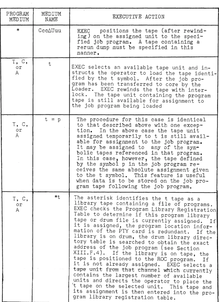
PROGRAM MEDIUM: This field defines the type of input medium on which the job program resides. It contains:
a) The symbol "T" to denote UNISERVO* IlIA, or
b) the symbol "A" to denote UN ISERVO IIA, or
c) the symbol "C" to denote UN ISERVO IIIC,
d) The symbol "*" to denote that the MEDIUM NAME field which follows contains an
absolute assignment.
MEDIUM NAME: This field contains the name or location of the medium contain-ing the job program. It con-tains ei ther :
a) the symbol "Ccc.6Uuu" where cc and uu specify the abso-lute channel and unit loca-tion of the job program, or b) the symbo 1 II *t
=
p/rr"where * defines the tape symbol t as denoting a libra-ry of programs. This desig-nation is optional. The tape symbol t ,is the alphanumerio
3This is the tag which appears in the PRO line of a SLEUTH
source program. It is expanded to 12 characters by the Assem-bly System with the right-most 6 characters filled with spaces.
*Tradernark of Sperry Rand Corporation.
UP 2577 Rev. 1 7
RUN TYPE:
8
name (one to six characters) of the tape containing the
job program. This is the only subfield which must be pre-sent if this form of the MEDIUM NAME field is used.
The = symbol equates the tape symbol to the program symbol p. The latter is the alphanumeric name (one to six characters) used in the
job program to refer to a tape. The presence of the symbol p in this field causes all job program references to this symbol to be replaced at load time by the absolute channel and unit assignment of the tape containing the
job program. The logical channel associated with this tape is defined with an asterisk on the FAC Card (see below).
rr consists of two decimal digits representing the
rela-tive location of this job program on the program libra-ry tape named in the t sub-field. This subfield is used only when the asterisk
(*)
subfield is present.
The MEDIUM NAME field is further discussed in Section
v.
This field may contain
a) the symbol
"s"
to indicate that this job must run serially.b) the symbol Ifpn to indicate
that this job may run con-currently with other jobs.
c) the symbol "E" to indicate that this job is an exter-nal rerun (See Section XIII).
d)
e)
PRIORITY:
MIX TYPE:
ESTIMATED TIME:
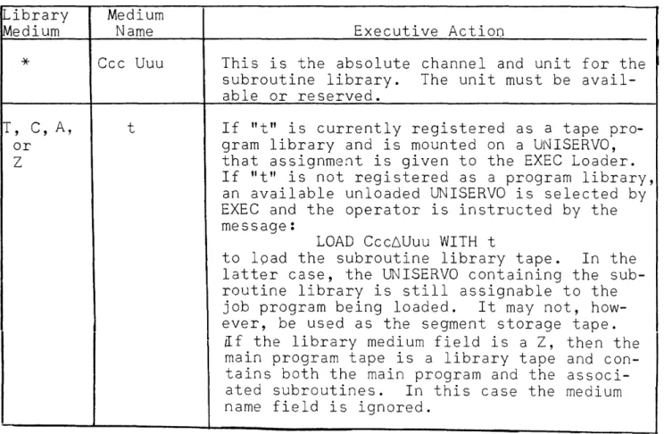
LIBRARY MEDIUM:
UP 2577 Rev.l
the symbol "I" to indicate that this program must run independently.
the symbol
"RU
to indicate that this job is a real~time program. From 1 to 5 charact~rscontain-ing the sequence, priority, and precedence assignments for the job request. The first two decimal digits are sequence numbers which specify the order of execution of jobs with ident-ical priorities and precedences other than Z63. The third char-acter in this field is the alpha-numeric priority, with
"A"
signi-fying the highest priority. The last two characters are decimal digits representing the precedence value. The minimum requirement for this field is the alphabetic priority. If the precedence is omitted, it is given a value of 63. For this case the priority must riot be l. (l 63 is reserved for permanent jobs.) The pre-cedence values range from 0 to 63, while the sequence values may vary from 1 to 63.This field assigns the job to either the compute-limited class or to the I/O limited class of programs. It is used as a basis for distributing control
to the operating job ·programs (see Section VIII). This field may contain.
a) the symbol IIp'' to denote an
110 limited program, or
b) the symbo 1
"e"
to deno te a compute-limited program.Up to four decimal digits giving an estimate, to the nearest min-ute, of the central computer time needed for the operation of the program. This estimate should be above the maximum and will be used to detect an infinite loop in ~
program.
This field defines the type of input tape which contains the subroutines to be included with
... o
...
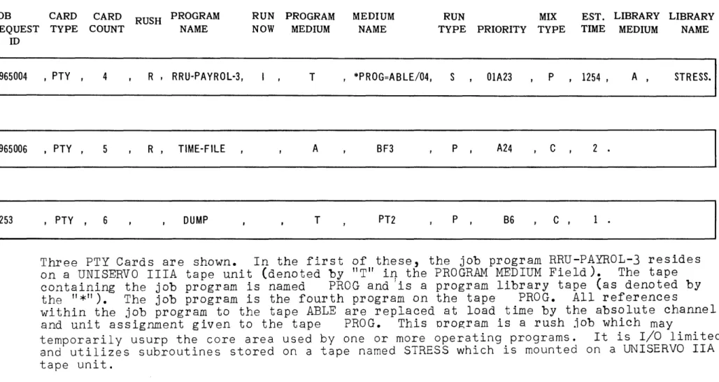
JOB CARD CARD RUSH PROGRAM RUN PROGRAM MEDIUM RUN MIX EST. LIBRARY LIBRARY
REQUEST TYPE COUNT NAME NOW MEDIUM NAME TYPE PRIORITY TYPE TIME MEDIUM NAME
ID
965004 , PTY, 4 R , RRU-PAYROL-3, T ,*PROG=ABLE/04, S 01A23 P , 1254, A , STRESS.
965006 ,PTY, 5 R, TIME-FILE A BF3 P , A24
c
2 .I 253 , PTY , 6 DUMP T PT2 P , B6
c ,
1 .Three PTY Cards are shown. In the first of these, the job program RRU-PAYROL-3 resides on a UNISERVO IlIA tape unit (denoted by "T" iI1- the PROGRAM MEDIUM Field). The tape containing the job program is named PROG and 'is a program library tape (as denoted by the
"*").
The job program is the fourth program on the tape PROG. All referenceswithin the job program to the tape ABLE are replaced at load time by the absolute channel and unit assignment given to the tape PROG. This program is a rush job wbich may
temporarily usurp the core area used by one or more operating programs. It is I/O limited and utilizes subroutines stored on a tape named STRESS which is mounted on a UNISERVO IIA tape unit.
~
I'\)
lJl
-.] -.]
~
CD <
.
... ...
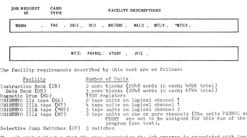
JOB REQUEST
10
965004
CARD TYPE
FAC , 08/3
FACILITY DESCRIPTIONS
IB/2 , MD/1500, MAI/2, MTl/4, *MT2/3,
MT/2: PAYROL: VTORY JP/3 •
The f~cility requirements described by this card are as follows:
Facility
Instruction Bank (IB) Da ta Bank (DB)
Hagnetic Drum (MD)
~NISEEVO IIA tape (MA)
UNISEEVO IlIA tape (MT) UNISERVO IIIAl. tape (*MT) UNISERvO IlIA tape (MT)
Selective Jump Switches (Jp)
Number of Units
2 core blocks
(2048
words in each;4096
total)3
core blocks(2048
words in each;6144
total)1500
r'egisters2 tape units on logical channel 1
4
tape units on logical channel 13 tape units on logical channel 2
2 tape units on one or more channels (The units PAYROL and VTORY are not to be assigned for this run of the
program (see text).
3
switchesThe asterisk indicates that the tape containing the job program is associated with logical channel 2 and, if not already assigned, w~ll be assigned to the same physical channel to which logical channel 2 is assigned.
LIBRAHY NAME:
the job program at load time (see manual on CLAMP). It may contain
a) the symbol "T" to denote UNISERVO IlIA, or
b) the symbol "A" to denote UNISERVO IIA, or
c) the symbol "C" to denote IIIC, or
d) the symbol "*" to denote that the LIBRARY NAME field which follows con-tains an absolute assign-ment.
e) the symbol Z to denote that the library medium is the same as the program medium.
This field contains the name of the library tape referred to above (see manual on 1107 LIBRARIAN).
Thp last field is followed by a period to indicate end-of-record. The PROGRAM NAME field may contain a hyphen ("_") character except as the first char-acter in that field. When the request is for an external rerun, the PROGRAM NAME field identifies the rerun dump (of which more than one may exist). Figure 2 contains three PTY cards for three differ-ent Job Requests. These cards follow the form des-cr ibed above.
2. Facility Description Card (FAC)
This card must be present for all jobs which are to be executed under EXEC control. The card con-tains a JOB REQUEST 10 field which is identical to the one described above for the PTY card, a CARD TYPE field with the symbol "FAC" to identify the card, and a number of FACILITY DESCRIPTION fields. These latter fields will be described in detail in Section IV on Facility Assignment. All required facilities other than those that are being transferred internally to the job program from another program must be listed on this card. The FAC Card is illustrated in Figure 3.
3.
Table Length Card (TAL)symbol "TAL" to identify the card, and a number of TABLE LENGTH INCREMENT fields. These latter fields are described in Section IV on Facility Assignment. The TAL card is illustrated in Figure
4.
4.
Transfer Card (TRN)This card is included in the Job Request for a program which uses facilities which are to be transferred to the environment of a following program or which are to be received from other programs. The following program requires a TRN card with a RECEIVING COUNT field to accept the facilities. (Section XIII describes some limitations.)4 The card contains a JOB REQUEST ID field, a CARD TYPE field with the symbol "TRN", a RECEIVING COUNT field, and a number of TRANSFER fields.
The RECEIVING COUNT field contains one or tWD de-cimal digits denoting the number of facilities to be received by this program from one or more pre-vious jobs in this sequence of jobs.
Each TRANSFER field consists of four subfields separated by "slash" (/) characters. These sub-fields are:
SUCCESSOR ID:
FACILITY TYPE:
the JOB REQUEST ID of the pro-gram to which the facility
transfer is directed.
If this subfield is preceded by an
*,
then EXEC itself is the recipient and the remainder of the subfield specifies one of tw'O possible types of transfer: REQ Facility contains one ormore Job Requests
PLB Facility contains a Program Library
Hence, Job Requests or a Program Library may be transferred to the Executive System.
the type of facility involved in the transfer as denoted by
4Facilities that are being transferred to this program are not reflected in the FAC Card requirements.
14
a) the symbol "0" for drum storage.
b) the symbol "T" for a magnetic tape to be transferred after rewinding. c) the symbol "N" for a magnetic tape
to be transferred without rewinding, or for the transfer of all facility types excluding core, drum, and jump switches.
If the "T" or "N" is preceded by an asterisk, the facilitY'will be given a reserved assignment upon release by the job program or by one of the succes-sive job programs to which it may have been transferred.
FACILITY NAME 1': the symbol by which this job pro-gram refers to the facility to be transferred.
FACILITY NAME 2: the name by which the program to which the facility is being
transferred, i.
e.,
the receiv ing program, refers to the facility. If the receiving program isEXEC and the facility contains a Program Library, then this sub-field contains the library iden-tity.
The subfields are written in the order
Facility Name 1/Facility Type/Successor ID/ Facility Name 2
on the TRN card. The card is illustrated in Figure
5.
If more than one TRN Card is necessary, they must be grouped together. The order of grouping may be random and the RECEIVING COUNT field may be on any card of the group.
5.
Parameter Card (PMn)A job program may require a set of input parameters to determine or select options of execution. These parameters are entered via the PMn Card. The card contains a JOB REQUEST ID field, a CARD TYPE field with the symbol IPMn" where n is a decimal digit from 0 to
9,
and a PARAMETERS field of up to66
characters. This card is illustrated in Figure 6 and discussed in detail in Section V.
I\) (J1 -...] -...]
:::0
(1)
<:
.
...
01
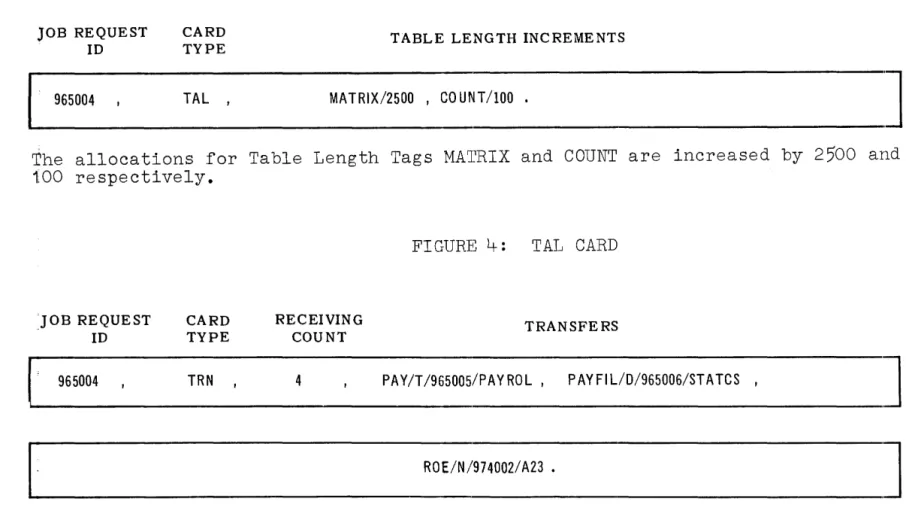
JOB REQUEST ID
CARD
TYPE TABLE LENGTH INCREMENTS
965004 TAL , MATRIX/2500 , COUNT/IOO •
I . . . - - - -_ _ _ _ _ _ _
'J
The allocations for Table Length Tags MATRIX and COUNT are increased by 2~0 and 100 respectively.
:JOB REQUEST ID
CARD TYPE
RECEIVING COUNT
FIGURE 4: TAL CARD
TRANSFERS
1~·
__
9_6_50_04 _________ T_R_N ________ 4 _______ P_A_Y_/T_I_96_5_00_51_P_A_Y_RO_L __ , __ P_A_Y_FI_L_/D_I_96_5_00_6/_S_T_AT_C_S __ , ___________~
I
~
___________________________________
R_O_E_/N_/_'97_4_00_2/_A_2_3_. _____________________________J
Four facilities are to be received by this program from previous jobs in the se-quence. The magnetic tape PAY is to be 'transferred after rewinding to job number 965005 and is to be referred to therein as PAYROL. (PAY might represent the up-dated master payroll file which is to beeome the input to the next payroll main-tenance run.)
JOB REQUEST
ID
CARD
TYPE PARAMETERS
965004 PMl , (required parameters - up to 66 characters)
The parameters are transferred to the $PARAM table of the job program. Since EXEC does not edit these parameters, "blank" characters are also transferred.
FIGURE 6: PMn CARD
Note 1: Information placed in the $PARAM table at assembly time is not superseded by the parameter card information.
C. General Schedule Information
1. Entering Requests
Job requests may be entered into the system at any time. Each job request identity in the schedule at anyone time must be unique. Any job request with a nonunique identity will be rejected at time of entry into the schedule. The only exception to the rule occurs when a job request in the schedule is in a suspended state. Here entry of a new job request with the same identity results in the new job request replacing the old one.
The last job request of a sequence of requests must be followed by a job request termination card. The contents of the TERM card are:
a) Right parenthesis in columns 1 through 8 and 73 through 80.
b) Plus sign in columns 10 through 22. c) All other columns are blank.
2. Indication of Schedule Completion
The completion of the schedule function is signalled by the message:
*jrid*6SCH6ACK or INT*jrid*6SCH6ACK
The job request
ID
displayed in the message is that of the last good job request processed. When the job request tables are filled, all job request cards following the last goodcard are passed over until the termination card is encountered.
3. Job request card errors will result in error typeouts on the console printer. Any error detected will cause the job re-quest in re-question to be bypass~d. The error message format is either:
SPb*jrid*6ERnn or INT6SP6*jrid*6ERnn
where
SP indicates schedule processor
INT indicates request schedule came to EXEC via an internal transfer
jrid is job request ID
nn is error code
The error codes and their description are listed below:
ERI Job request ID of current job too long. Message shows previous job request ID.
ER2
ER3
UP 2577 Rev. 1
Card type field too long.
Illegal card type.
ER4 Cards out of order - PM
ER5 TAL name too long or illegal character on the TAL card
ER6 TAL number too long
ER7 Illegal character on TRN
ER8 TRN field too long
ER9 FAG name too long
ERIO Reserve on more than one card
ERII Illegal facility requested
ER12 Illegal character on FAC.
ER13 Illegal sequence on FAC
ER14 FAG asked for too large a core block
ER15 Two FAG have
*
ER16 Job program name too long.
ER17 Illegal character or sequence on PTY
ER18 Illegal number of characters in some field on PTY
ER19 Rerun but no absolute units on PTY
ER20
ER2I
ER22
ER23
ER24
ER25
ER26
ER27
ER28
ER29 ER30
ER3I
ER32
ER33
ER34
Card count on PTY and cards in job do not match
PTY cards not grouped together
FAG cards not grouped together
TAL cards not grouped together
TRN cards not grouped together
First card of new jrid is not a PTY card
Duplicate request I.D.
No IBANK specified on facility card
Illegal RUSH field on the PTY card or FAC card is not the second card of the job request.
Job request core storage table filled. PM number is not numeric
Matched priority and precedence of a job in schedule but no sequence number on new job.
Matched priority and precedence of a nonsequence job.
Priority and precedence of ~63 but not a permanent job. FAC card ended with colon but next card is not FAC card starting with a tag field~
D. Schedule by Paper Tape
1. General
a) The paper-tape header may be any length up to three feet. If something other than master spaces (blank tape) has not been read after three feet of tape, an error message will be produced.
b) The trailer may be any length greater than one inch.
c) Each equivalent of a "card" is terminated by a period (.).
d) The first "card" on tape must start with a carriage return followed by the word SCHEDULE. Any number of characters up to 70 may follow this word. The first "card" is term-inated by a period.
e) The formates for the PTY, FAC, TAL and TRN are the same as defined for cards. The format for the PM card includes another field to define the number of characters which follow. The format is as follows.
jrid, PMn, x, (parameter characters)
if x = a period (.) the parameter characters will be read until a period is encountered
if x
=
special character (Fieldata code 76, Flex code upper case S), the 66 characters after the comma will betaken as parameter informationif the x field is missing, reading will stop.
f) The stop code (Fieldata code 57, Flex Code 43) is used to define end-of-data, except in the parameter characters on the PMn "card".
g) Ten consecutive master spaces (one inch of blank tape) after any legal character and before the stop code will cause termination of reading with an error message.
h) A backspace code (Fieldata 77, Flex Code 61) may be used at any time to cancel the characters typed so far for a particular "card". (Except in the parameter characters of the PMn card.)
2. Fieldata Code
All Fieldata codes are legal on the PMn "card". The following characters are legal for the PTY, FAC, TAL, and TRN "cards":
05 through 37 (A-Z). 60 through 71 (0-9).
41 (~J ~50 (* },53,(:J ,56
l,},.7
4 (I.} ,75, ( .), and 44 (=).All other characters will be ignored on these "cards".
3. Flex Code
20
All the rules that apply to Fieldata code apply to Flex code.
The fullowing are the characteis allowed and their Fieldata
equivalents (note that upper and lower case punches are necessary in some cases). Unless noted otherwise, all characters are
lower case.
a. PTY, FAC, TAL, and TRN cards
Alphabetics - lower case letters a - z Numberics - lower case numbers 0 - 9
Flex character Flex code
Upper case - (dash) 56
+ 54
- (dash) 56
46 (vert. slash) 50 42
=
44back space 61
stop code 43
tape feed
00
space ¢4
b. PM Card
All characters as shown above plus:
Flex character Flex code
upper case S 24
upper case U 34
upper case L 11
tab 51
carriage return 45
upper case ) 42
upper case P 15
upper case H 05
Flex character Flex code
upper case G 13
upper case N 06
upper case D 22
upper case ( 46
upper case T 01
upper case Q 35
upper case E 20
upper case A 30
upper case C 16
Fieldata equivalent
*
/
=
back space stop code master space
space
Fieldata equivalent
special upper case lower case tab
carriaJe return
+
<
Fieldata equivalent
>
"$
(underline) ("
?
(apostrophe)
Code delete 77 is ignored on any card type.
E. Deletion of Job Requests
It may be necessary to delete a job from the schedule before or after it has been initiated. To accomplish this, the operator types in a request of the form:
DEL jrid or DEL*jrid
where DEL identifies it as a request to delete a job request from schedule
jrid represents the alphanumeric JOB REQUEST ID which was associated with this job on all of the job request cards.
* is optional and causes the remaining jobs in the sequence, if any, to be deleted.
The EXEC response to this message will be one of the following:
DEL ACK DEL RUN
DEL
06
IN ERRORUP 2577 Rev. 1
- job has been deleted
- the job request cannot be deleted be-cause it is operating (the operator must use the "TER" message to
termin-ate the running program.)
- job request ID not in schedule.
III. SELECTION
There are two phases to the Selection function of the Exe-cutive System. The first phase involves selecting, accord-ing to priority and precedence relationships, a candidate for initiation from the job schedule. The second phase is an allocation check to determine if the facilities required by the candidate are available. If they are available, the job program is loaded and initiated. If they are not avail-able, then another candidate is selected. This process is continued until all jobs in the current priority class have been checked for possible initiation. When this occurs,
the Selection function terminates its operation.
A. Operation
The Selection function operates whenever one of the following changes occur:
1. Job Requests have been added to the schedule
2. A job program, or EXEC itself, has released a facility from its operating environment.
3.
The operator has made a facility available.4.
A job program has terminated and all of its faci-lities have been released and made available for reassignment.5.
A job program has just been initiated.Following selection of a job, control is given to the Loading function of EXEC to load and initiate the program. When the job has been initiated, control reverts back to Selection which attempts to select another job.
B. Method of Selection
Seven factors are used to select the next candidate from the job schedule. They are: RUSH designator;
priority assignment, in the order A to Z from highest to lowest; precedence within a priority, in the order from 0 to 63; sequence assignment, in the order 1 to
q3; Run Type; and Mix Type.
All of this information is made available in the Job Request PTY Card as described in Section II.
1. Permanent
UP 2577 Rev. 1
If the permanent indicator is set as a result of a P in the RUSH field of the PTY card, the job is skipped regardless of other information.
24
The permanent job may be selected by the use of the second version of the
SEL
unsolicited message (see table 11). Thus resulting in assignment of a running jrid, priority, precedence, and sequence to the per-manent job. The original permanent job remains in the schedule and can be removed only by use of aDEL
unsolicited message.
2. RUSH
When a RUSH job is detected, all currently operat-ing jobs usoperat-ing the needed core facilities.a~e.in terrupted and the RUSH job is loaded and lnltlated.
3. Priority
All jobs receive a priority from A to Z, A being the highest. If prorities are omitted from the job request,
EXEC
assumes a "Z" priority. All jobs, or sequences o£ jobs, in given priority class must be initiated before a job from the next lower class will be con-sidered as a candidate. This scheme of stepping within priority class may be altered by operator intervention. A type-in of the form:TPR
will cause the Executive to "terminate priority restriction." The priorities 'will then be ex-amined sequentially until a candidate is selected or until the end of the job schedule is reached. To return to the scheme of initiating all jobs within a given priority class before examining the next class, the operator may "initiate pri-ority restrictiod'by means of the type-in
IPR
4. Precedence
Precedence assignment ranges from 0 to
63.
If precedence is not assigned in the Job Request, EXEC will assume a value of63.
The jobs in apriority class will be examined sequentially ac-cording to precedence value until a candidate for initiation is selected. When the precedence values are equal, candidates are examined in the order in which the job requests were submitted.
5. Sequence
The sequence assignment serves to specify the order in which a set of associated jobs are to be run.
The jobs are associated by assigning the same priority and precedence values to each of them. This associa-tion can be used for a set of jobs where the output of one job is used as input for the next job, or for a set of jobs which are to be tested.
Sequence numbers range from 1 to
63.
All jobs with identical priorities and procedence values are run serially with respect to each other inthe order specified by their sequence numbers. The sequence numbers do not .. however, have to be consecutive. If the sequence numbers of two or more associated jobs are identical, these jobs will be run concurrently if facili ties permi t.
Following completion of a job (or jobs, if two or more ran concurrently) in sequence, the
follow-ing job in sequence is initiated if facilities permit. If the following job in the sequence does not pass the facility availability check this fact is remembered and the job is always the first candida te for selection follow"ing any release of facilities. After the first job program in a sequence has been initiated, the following j~b requests are given top priority regardless of the current priority level.
This concept of scheduling permits the definition of more than one set of jobs to be run in sequence at the same priority level. The facilities as-signed to one job may be transferred to a succeed-ing job in the sequence. The ROC program output tape from SLEUTH or from an 1107 compiler may be used as the input tape.to EXEC for tes~
ing the assembled programs. (See Section XIII).
Although jobs in sequence are run serially with respect to each other, they still may be defined for parallel, serial, or external rerun types of operation, with respect to all jobs not in this sequence. There is, however, one restriction; external reruns may only be initiated at the beginning of a sequence and are always initiated serially.
When a job program in sequence is terminated~ with or without error prior to its normal completion, the operator has the option of deleting the remain-ing jobs in the sequence. (See Section
XII.)
6. Serial Selection
UP 2577 Rev. 1
For a given priority, jobs to be run in serial will be selected as candidates for initiation when no job programs are currently operating, or after all jobs to be run concurrently have been
.~p'i tia ... t.~d .. " .... "._ .. ~1
...
.t.h.i,s .... ,.tJrn~...
th~._.ppetgt.p:r .... is ... .llpt.J:ri,ed to load the program tape on an assigned tape unit if it is not already loaded. The serial job will not be loaded, however, until all currently oper-ating programs have terminated.5
7. Mix Type
All job programs that are I/O limited in their op-eration will be initiated into a mix of concurrent-ly operating programs before more than one compute-limited job program is initiated. This check ap-plies to all programs run under EXEC control
ex-cept for succeeding job programs in a sequence of jobs.
C. Facility Check
Once a candidate for initiation has been selected, a check is made of the Facility Availability Table to determine if the facilities required by this program are available. (The required facilities are sub-mitted in the Job Request FAC card.)
In order to determine the availability of the requi-site facilities, the following questions are asked~
1. Are there enough channels available for each type of facility?
2. Are there enough units available for each channel?
3.
Are there enough consecutive locations on each requested drum channel?4. Does the core bank with the largest group of con-secutive 2048-word blocks have enough to satisfy the larger of the two core requirements (IBANK or DBANK) .5
5.
Is there a block of locations in the other core memory bank large enough to satisfy the smaller of the two requirements? If not, is there enough left in the assigned block of the first core bank checked.5If the answer to any of these question is no and at least one job program is currently running, the job request will be temporarily bypassed as a candidate for initiation. If the answer to any of these ques-tions is no, and no job programs are currently running, the job request will be suspended and the typeout:
*jrid* FAIL FAC SUS.
will occur:
D. Selection Interruption
In order to provide the computer operator with some measure of control over Executive System operation, EXEC will accept the type-in:
HSL
which causes it to halt the process of selecting jobs for initiation. In order to cancel this order and to direct
EXEC
to resume the selection of jobs for initiation, the type-inSEL
is given. This type-in has meaning only when it follows an "HSL" message.
A more exacting degree of control is allowed by specifying a job request ID with the HSL type-in. This causes the specified job request to be suspended as a candidate for selection until the computer opera-tor reactivates the job request with the type-in
SEL jrid (See Table 10)
Job requests suspended by EXEC after passing the facility check will not be eligible as candidates for selection until the operator reactivates them with the SEL jrid message.
E. EXEC Message Relating to Job Selection
When all unsuspended jobs in the schedule have been selected, the following message is typed:
SCH SELECTED
When the schedule is selected and no jobs are running, the following message is typed:
SCH COMPLETE
When a job which meets the requirements of the facility check has been selected but there is no available UNISERVO from which to load the job program, the following message is typed out:
*jrid*NO AVAIL INPUT TAPE
IV. FACILITY ASSIGNMENT
Object programs require a certain environment in which to ooerate. This environment is some subset of the total
f~cilities comprising the 1107 system. Since one or more
programs may be operating and using some facilities when a new program is being initiated, all facilities will have to be referred to by the programs in a symbolic manner. The Executive System will assiqn an available facility to every symbolic facility referenced by the program and listed as a required facility on the FAC card. Available facilities are those not used by EXEC or by any other program.
The various facilities to be assigned by EXEC may be grouped into three major classes:
1. Core memory which includes:
a~ an instruction storage block
b. a data storage block
2. Drum memory for each program segment storage and data storage.
3. I/O equipment which includes:
a) magnetic tape b) paper tape reader c) paper tape punch d) card reader
e) card punch
f) High-Speed Printer
g) console selective jump switches
These facilities are uniquely assigned to a job program for its use. They are returned to an available status when the job program terminates its operation or when it releases a facility (see IV. E. below).
The 1107 Assembly System produces two outputs which are signi-ficant for facility assignment by the Executive. One of these, the facility description data which appears on the listing output of the assembly of the job program, is used to prepare the FAC card of the job request. The Executive System checks the information on the FAC card to determine if the required facilities are available. If they are, the second of the two outputs, the modification record of the assembled program, is used to assign the required facilities. Limited changes in the facilities required in the job program may be made via the job request'. The 'mod:i:ficat±Ofl' reeord'is'parto-f"the ROC program output of the assembly.
The FAC Job Request cards are discussed below. The Modi-fication Record is described in Section V.
A. Facility Descriptions (FAC Card)
The form of the FAC card w'as illustrated in Figure
3.
The card is identified by the symbol "FACti in the second field. The first field contains the alphanumeric identity of the job request.
The remaining columns of the card are divided lnto fields separated by commas. These fields contain the facility requirments organized by unit tape, channel, and number of units. The last field may be followed by a period, comma, or blanks. Additional FAC cards with the same format may be included. If all unit tapes of facilities to be deleted will not fit on the current FAC card, the card can be terminated by a colon in which case the remaining tag subfields must be in-cluded as the first entries on the next FAC card.
The FACILITY REQUIREMENT fields take the general form
where
*ff cc/uuuuuuu : s:s,
* identifies the logical channel with which the tape containing the job
program is to be associated.
ff is a 2 let ter code defining the type of facility (see below).
cc are two decimal digits in the range 0-15 denoting the logical channel number. When cc=O or is omitted, it implies that no specific channel associations are necessary for the units specified in the corresponding
u~its field. This channel designation should be used only when the number of units specified is greater than one. 6 When cciO, logical channel
numbers 1 to 15 serve to associate those units which will operate efficiently with each other on a common channel.?
uuuuuuu is a one to seven decimal digit sub-field specifying the number of peri-pheral units, registers, or the num-ber of 2048 word core-memory blocks required for the corresponding faci-lity.
e This concept does not apply to drum channel requirements.
'Note that these channel assignments are logical and do not necessarily correspond to physical 1107 I/O channels.
s is the symbol for a facility that is normally required by the job program, but which is not to be assigned for
this run. This unit is not included in the count of units required on this logical channel. This subfield is not applicable to core or drum facilities.
The FAC cards describe the required facilities in terms of numbers and logical channels. The same information together with the symbol for each facility is contained in the Modification Record of the job program. The two descriptions must match. The symbol "MT 1/2" on the Job Request FAC card conditions EXEC to expect a mini-mum of two symbolic tape references to be defined in
the Modification Record for logical channel 1.
The asterisk
(*)
identifies the logical tape channel with which the magnetic tape containing the job program should be associated for efficient operation. This specification will be honored if the job program tape is not already loaded. If it is already loaded, then an attempt is made to allocate the logical channel re-quirement to the channel containing the job program tape. The count of the number of units required for a channel marked with an asterisk must include the tape containing the job program.The possible values of the ff, cc, and uuuuuuu sub-fields are indicated in Table 1.
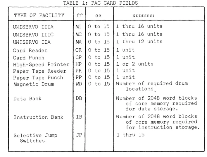
TABLE 1: FAC CARD FIELDS
TYPE OF FACILITY ff cc uuuuuuu
UNISERVO IlIA MT 0 to 15 1 thru 16 units UN ISERVO IIIC MC 0 to 15 1 thru 16 units UN ISERVO IIA MA 0 to 15 1 thru 12 units Card Reader CR 0 to 15 1 unit
Card Punch CP 0 to 15 1 unit
High-Speed Printer HP 0 to 15 1 or 2 units Paper Tape Reader PR 0 to 15 1 unit
Paper Tape Punch PP 0 to 15 1 unit
Magnetic Drum i\ID 0 to 15 Number of required drum locations
.
Data Bank DB Number of 2048 word blocks of core memory required for data storage.
Instruction Bank IB Number of 2048 word blocks of core memory required for instruction storage. Selective Jump JP 1 thru 15
Switches
NOTE: All values of uuuuuuu are given for one required channel. Additional Card Readers, etc., may be assigned to other
logical channels.
The repeated FACILITY REQUIREMENT fields must be organized according to the following rules:
1) Fields must be grouped according to facility type.
2) The fields of a given type must be listed according to the amount of units or memory locations required, with the largest requirement listed first.
3) The logical channel zero requirement, if present, must be listed as the last requirement for that facility type.
The efficiency of the facility availability check performed by EXEC will be increased if the facility requirements most apt to be unavailable are listed first on the job request FAC cards. This is left to the discretion of the user.
B. Changes in Facility Requirements
1. Peripheral Equipment (excluding drum)
UP 2577 Rev. 1
Certain types of programs (the 1107 SLEUTH Assem-bly System, the 1107 SORT/MERGE Program) have fa-cility requirements which vary according to the type of operation and other factors. To accommo-date programs of this type, EXEC will recognize certain variations in the requirements definition fields of the FAC Card. These variations may specify modifications which are to be made to the program's facility requirements as was established at assembly time. The modifications to be made fall into three categories: partial deletion, complete deletion, and minimum requirements.
a. Partial Deletion: This is accomplished by identifying those units (tape, printer, card reader, etc.) which are not to be assigned to this job for this particular operation. As an example, consider the requirement defined by the field
b.
c.
MT 2/5
This states that logical tape channel 2, as defined in the Modification Record of the job
program, must contain exactly
5
units assigned to the program. If tWD units are not needed for this run of the program, then the field can be chpnged to readMT 2/3 : LIST : NOLIST,
where "LIST" and "NOLIST" are the symbolic unit tags for the units which are not to be assigned. Console selective jump switches can be deleted only in this manner. The comments i~ the follow-ing two paragraphs (b. and c.) do not apply to jump switches.
Complete Deletion: This is accomplished by omitting the complete field from the FAC Card. For example, if all tapes on logical channel
2 in the above example are not to be assigned to this job program for this run, then the field MT 2/5 would not be listed on the FAC card. This is legal only if none of the five tapes on logical channel 2 are listed in the Modification Record of the program as part of
th~ m~nimum ~9.u~p'ment conf~gura tion.
Minimum Requirement: Each unit symbol listed in the Modification Record of the job program may be defined in the source code as part 0f the
minimum operating requirements of the program.
Suppose that
3
of the tape units assigned to logical channel 2 in the above example were defined as belonging to the minimum configu-ration. Then the field "MT2/5"
could be written as "MT 2/3" on the FAC Card if onlythe minimum configuration for logical channel 2 is required.
If, after the deletions have been made, a logical channel requires more units than were requested in the job request, the loader attempts to make the additional assignments. This does not apply when complete deletion was requested by omitting the field from the FAC card. If the additional facilities can be assigned, the operator is noti-fied that some type of I/O equipment was updated and loading is continued. When the required number of units are not available, loading is terminated with a message on the typewriter indicating insufficient I/O available. The job request is suspended, if part of a sequence, or deleted by the EXEC and a new job may be initiated.
2. Core and Drum (TAL Card)
The fields of the FAC card which define the number of drum and core table locations may be changed as required within the limits set by the program. The minimum number of required locations for each drum channel and for core table storage is calculated by SLEUTH. This number may be increased but never de-creased. This number is used to determine in advance of program loading if there are enough drum and core locations available for use by the program. If on loading it is found that the program demands more drum registers than the number specified in the job request, an attempt will be made to allocate that amount. If the attempt is successful, the operator will be notified that the drum requirement in the
job request has been updated and loading will be
continued; if the additional amount is not available, the job request will be suspended, if part of a
sequence, or deleted with an appropriate message on the typewriter and a new job will be considered for initiation. The drum requirements for a particular logical channel need not appear on the FAC card if all drum tables on the channel are assigned via ex-ternal transfers to the program.
The TAL card is illustrated in Figure
4.
The TABLE LENGTH INCREMENT fields are of the forml/iiiiiii
where 1 is a core or drum Table Length Tag as defined in the source code and consists of from 1 to 6 alphanumeric characters; iiiiiii is a 7 digit decimal number which is the increment to
the length of the table.
When the TAL Card is used to increase the length of se lected core and drum tables, the overall core and drum requirements will be changed. This change must be reflected in the FAC Card.
C. Allocation of Facilities
Facilities will be allocated to job programs according to the following rules. The word "channels", as used in these rules, is limited to those channels which con-tain the same type of peripheral equipment. Note that
card reader and card punch are different types.
All channel assignments are made on the basis of the facility requirements indicated on the FAC cards. Unit assignments within the assigned channel are made at load time on the basis of the information contained in the Modification Record of the program.
1. Peripheral Facilities (excluding drum)
UP 2577 Rev. 1
a. Channel Assignment: The channel assignment procedure takes into consideration the MIX TYPE of the program. Channel assignments for I/O limited programs are taken entirely, if possible, from channels that currently do not contain units assigned to I/O limited programs. If this is not possible, or if the program is compute-limited, then this check is not made and the units are assigned normally.
The logical channel with the largest unit re-quirement will be assigned first to the chan-nel with the largest number of available units. Then the logical channel with the se-cond largest unit requirement will be as-signed to the channel that, prior to the first assignment, had the second largest num-ber of units available. This process is con-tinued until all logical channels have been assigned to physical channels.
Units not associated by channel will be as-signed to available channels in a manner de-signed to leave, if possible, an equal number Qf .a,v.ai,lable ... uni ts. ouea.ch .. .,cbanuel ...
b. Unit Assignment: The symbolic unit definitions contained in the Modification Record of the job program are assigned in order of definition to available units, in ascending sequence, on the previously assigned channel.
8
When assigning tape units, those that have been defined at assembly as input units are
assigned to the lowest numbered available
units that are currently rewound with interlock.
2. Magnetic Drum Facilities
a. Channel Assignment: Drum register requirements are treated as one conse