IJEDR1601036
International Journal of Engineering Development and Research (www.ijedr.org)1
Increasing the Charging Efficiency of Solar Panel and
Improving the Performance by Using PIC Controller
and Gear Motor Based Cleaning Method on Voltage
Drop
Sitanshu Tiwari1, Kartik Parolia2
MBA Oil and Gas B.Tech electronics and communication
1 Professor, Hemangi Pujara M.Tech Electronics and Communication Engineering, RK University, Rajkot, Gujarat, India 2 Dr Ratna Banarjee, Assistent Professor, UPES College of Management and Economics studies, Dehradun Uttarakhand, India ________________________________________________________________________________________________________
Abstract- Solar energy sources play an Vital role in Generation of electricity (Energy). There are various renewable energy
resources like wind, solar, geothermal, ocean thermal, tidal and biomass can be used for generation of energy or else we can say electricity for meeting our daily energy needs. The best option for electricity generation can be Sun (solar energy) as it is available in abundance and is free to harness. On an average the sun shines for about 6hrs annually in India also the sunshine shines in India for about 9 months in a year. Electricity (Energy) from the sun can be generated through the solar photo voltaic modules (SPV).
The Photo voltaic cells comes in various power output to meet the load requirement. Maximization of power from a solar photo voltaic module (SPV) is of special interest as the efficiency of the SPV module is very low. A peak power tracker is used for extracting the maximum power from the photo voltaic module. The present work describes the controlling the peak power (SPPC) for the SPV module connected to a battery which is used as a load. A Microcontroller is used for control of the algorithm. The peak power controller is developed and tested successfully in the laboratory.
Solar peak power controller is used in photovoltaic systems to maximize the photovoltaic array output power, irrespective of the temperature and irradiation conditions and of the load electrical characteristics .The main difference between the method used in the proposed SPPC system and other techniques used in the past is that the PV array output power is used to directly control the dc/dc converter, thus reducing the complexity of the system. The resulting system has high-efficiency, lower-cost and can be easily modified to handle more energy sources (e.g., wind-generators).The efficiency of the panel decreases as time passes due to the accumulation of dust particle on the panel ,which is hampering and an big hindrance for charging the battery or else we can say load which is connected to the set up ,for this we would use an geared motor which would be connected with the wiper and it would help in cleaning the panel on daily basis as the voltage drop would be there the current study has been done on the basis of LDR sensor which is not so appropriate for the industrial application.
________________________________________________________________________________________________________
I.INTRODUCTION
Photo voltaic (Solar Electric)
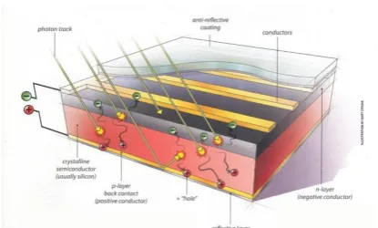
Photovoltaic Cells or devices can generate electricity directly from sunlight by using electronic circuit. Electrons in these materials are charged by solar energy and can be induced to travel through an electrical circuit, powering electrical devices or sending electricity to the grid. PV devices can be used to power anything from small electronics such as calculators and road signs up to homes and large commercial businesses.
How does PV technology work?
IJEDR1601036
International Journal of Engineering Development and Research (www.ijedr.org)208
Fig 1. A typical crystalline silicon solar cellSolar Panels
Fig 2. Solar Panel Each solar cell has a current of 3 amps and a voltage of 6 volts
The output of a solar panel is usually stated in watts, and the wattage is determined by multiplying the rated voltage by the rated amperage. The formula for wattage is VOLTS times AMPS equals WATTS. So for example, a 12 volt 60 watt solar panel measuring about 20 X 44 inches has a rated voltage of 17.1 and a rated 3.5 ampere.
V x A = W 17.1 volts times 3.5 amps equals 60 watts
If an average of 6 hours of peak sun per day is available in an area, then the above solar panel can produce an average 360 watt hours of power per day; 60w times 6 hrs. = 360 watt-hours. Since the intensity of sunlight contacting the solar panel varies throughout the day, we use the term "peak sun hours" as a method to smooth out the variations into a daily average. Early morning and late-in-the-day sunlight produces less power than the mid-day sun. Naturally, cloudy days will produce less power than bright sunny days as well. When planning a system your geographical area is rated in average peak sun hours per day based on yearly sun data. Average peak sun hours for various geographical areas is listed in the above section.
Solar panels can be wired in series or in parallel to increase voltage or amperage respectively, and they can be wired both in series and in parallel to increase both volts and amps. Series wiring refers to connecting the positive terminal of one panel to the negative terminal of another. The resulting outer positive and negative terminals will produce voltage the sum of the two panels, but the amperage stays the same as one panel. So two 12 volt/3.5 amp panels wired in series produces 24 volts at 3.5 amps. Four of these wired in series would produce 48 volts at 3.5 amps.
Parallelwiring refers to connecting positive terminals to positive terminals and negative to negative. The result is that voltage stays the same, but amperage becomes the sum of the number of panels. So two 12 volt/3.5 amp panels wired in parallel would produce 12 volts at 7 amps. Four panels would produce 12 volts at 14 amps.
+
+ +
+
+
+ +
- - -
- - -
- Series
IJEDR1601036
International Journal of Engineering Development and Research (www.ijedr.org)209
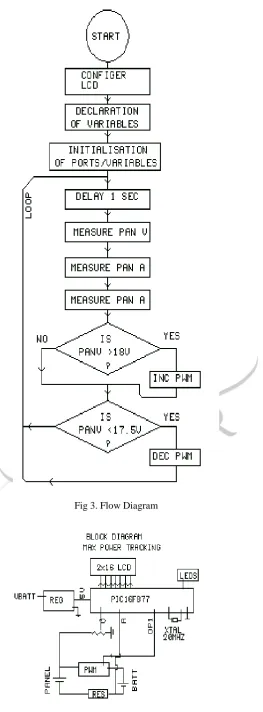
II.FLOW DIAGRAMIJEDR1601036
International Journal of Engineering Development and Research (www.ijedr.org)210
Fig 4. Block DiagramSystem is based on PIC 16F877 Controller. Power supply gives regulated 5V DC from 12V DC Battery Voltage input. 2X16 LCD is there to display system parameters on the display panel voltage and panel current is displayed on the LCD. 2 PWM Controller regulates the power going to the battery from panel. Resistance senses the current which is fed to the microcontroller for measurement; 20 MHz crystal provides clock frequency to the microcontroller. If panel voltage is less than 17.5 charging power is decreased and when more than 18v charging power is increased, thus peak power charging is always maintained as voltage goes down below 4.2 v the wiper of the panel starts to move in order to clean the panel and keep it ready for charging.
III.CONCEPT OF PWM
PWM - Pulse Width Modulation can generate signals of varying frequency and duty cycle. The PIC16F887 microcontroller has two such modules. Both of them are identical in normal mode, with the exception of the Enhanced PWM features available on only Proposed Charge Controller
The main parts of a solar system are PV cell, solar charge controller, storage battery and load the proposed charge controller consists of four parts.
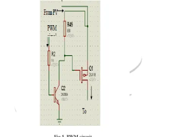
Voltage scaling stage: It is used to scale the voltage measured form the battery or PV cell to the level that can be measured by the microcontroller (from 18V to 5V).The voltage scaling stage can be implemented by using a voltage divider circuit as shown in the figure below(R1=130kΩ,R2=50kΩ).
It is used in order to drive the correct charging voltage to the battery by using the PWM tech knowledge. The MOSFET transistor is a specialized type of transistor that is used for high current applications.
Fig 5. PWM circuit
IJEDR1601036
International Journal of Engineering Development and Research (www.ijedr.org)211
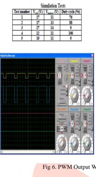
Fig 6. PWM Output WaveformIV.CONCLUSION
The overall cost of a stand-alone PV system can be reduced with proper battery-charging control techniques, which achieve high battery state of charge and lifetime, under continuously varying atmospheric conditions, which give rise to intermittent PV energy production. In this paper, a novel battery charging regulation system has been presented, consisting of a DC/DC converter controlled by a low-cost microcontroller unit. Advantages of the proposed method are:
(a)The PWM technique employed in the control algorithm assures maximization of the energy transferred to thebattery bank, and thus a better exploitation of the PV source is achieved.
(b)The battery lifetime is increased because the battery is operating at a higher state of charge.
(c)The battery-charging algorithm does not depend on accurate battery current measurements, thus reducing the current sensor accuracy required and subsequently the cost of the circuitry.
If we connect the battery to solar cell through switch, power received from the solar energy is about 60 to 70% of peak power, thus about 30% power goes unutilized. Instead we charge the battery through solar peak power controller, most of the power available is utilized in charging of battery, and so unutilized power loss is almost nil.
The biggest benefit of this circuit is its low cost, complexity compared to the circuit present in the market. This circuit is very useful during rainy season, or low line area where still electricity is not available. The charging efficiency also decreases due to the accumulation of dust particles as the day passes away which results into reduced charging efficiency by using this proposed circuit with automatic cleaner would clean the panel on voltage drop and would also increase the charging frequency by using PWM technique which would enhance charging as well as the battery life.
V.REFERENCES
[1] Dunlop, J. P., “Batteries and Charge Control in Stand-alone Photovoltaic Systems. Fundamentals and Application”, Working
Paper, Sandia National Laboratories, Photovoltaic Systems Applications Dept., Florida Solar Energy Center, Cocoa/Florida -. USA, 1997
[2]Ross, J., Markvart, T., and He, W.: „Modelling Battery Charge
Regulation for a Stand-alone Photovoltaic System‟, Sol. Energy, 2000, 69, (3), pp. 181 190 [3] M. H. Rashid, Power Electronics Handbook, Academic Press, 2001.
[4] Frede Blaabjerg, Florin Iov, Remus Teodorescue, Zhe Chen, „‟Power Electronics in Renewable Energy Systems‟‟, Aalborg University, Institute of Energy, IEEE transaction, 2006.
[5]Harprit Sandhu, "Making PIC Microcontroller Instruments and Controllers ",2008.