R E S E A R C H
Open Access
Multiple-access relaying with network coding:
iterative network/channel decoding with
imperfect CSI
Xuan-Thang Vu
*, Marco Di Renzo and Pierre Duhamel
Abstract
In this paper, we study the performance of the four-node multiple-access relay channel with binary Network Coding (NC) in various Rayleigh fading scenarios. In particular, two relay protocols, decode-and-forward (DF) and
demodulate-and-forward (DMF) are considered. In the first case, channel decoding is performed at the relay before NC and forwarding. In the second case, only demodulation is performed at the relay. The contributions of the paper are as follows: (1) two joint network/channel decoding (JNCD) algorithms, which take into account possible decoding error at the relay, are developed in both DF and DMF relay protocols; (2) both perfect channel state information (CSI) and imperfect CSI at receivers are studied. In addition, we propose a practical method to forward the relays error characterization to the destination (quantization of the BER). This results in a fully practical scheme. (3) We show by simulation that the number of pilot symbols only affects the coding gain but not the diversity order, and that
quantization accuracy affects both coding gain and diversity order. Moreover, when compared with the recent results using DMF protocol, our proposed DF protocol algorithm shows an improvement of 4 dB in fully interleaved Rayleigh fading channels and 0.7 dB in block Rayleigh fading channels.
Keywords: Network coding; Cooperative relaying; Joint network/channel decoding; Imperfect channel state information
1 Introduction
In cooperative communications systems, idle nodes have the capability to relay information from other active nodes. Hence multiple copies of the same signal can reach a given destination through independent fading channels, which result in potential spatial diversity gains. However, diversity gains are usually achieved with some loss in system throughput [1,2].
Network Coding (NC) has recently been introduced as a capacity–achieving routing scheme where intermedi-ate network nodes are allowed to combine several input packets into one output packet [3]. Recent results have shown that NC can also provide improved performance and energy efficiency compared with conventional net-work routing techniques [4]. However, besides the many
*Correspondence: [email protected]
Laboratory of Signals and Systems (LSS), French National Center for Scientific Research (CNRS) – École Supérieure d’Électricité (SUPÉLEC) – University of Paris–Sud 11, 3 rue Joliot–Curie, 91192 Gif–sur–Yvette (Paris), France
potential advantages and applications of NC over clas-sical routing, the NC principle is not without limita-tions. A fundamental problem that NC needs to take into account over lossy (e.g., wireless) networks is the so-called error propagation problem: corrupted packets injected by some intermediate nodes may propagate through the net-work until the destination, and might render impossible to decode the original information [5,6]. It is shown in [5,6] that error propagation can dramatically degrade per-formance and reduce the diversity order of cooperative networks.
Among the solutions that are currently being investi-gated to counteract the error propagation problem [4], joint network channel decoding (JNCD) is gaining a grow-ing interest [7]. The idea behind JNCD is the exploitation of the inherent redundancy of network and channel codes. In [7,8], it has been shown that, compared to conven-tional distributed turbo coding and separate network and channel decoding, JNCD can improve the performance of canonical two-way and multiple-access relay channels.
However, these results assume that only correct packets are forwarded from the relay to the destination. Recently, various relaying protocols have addressed the error propagation problem in cooperative communications. In [9-11], the authors propose soft relaying protocols. In soft-relaying, the relay does not take any hard decision of the input signals. Instead, the relay computes log-likelihood ratios (LLR) of network-coded bits and re-encodes them using a soft encoder. The relay then forwards encoded soft bits to the receiver. The disadvantage of this method is that it requires higher computational complexity at the relay, as well as larger bandwidth since soft values are transmitted to the destination instead of binary esti-mates. Another strategy is the so-called threshold-based relaying [12,13] where only decoded bits with reliability above a given threshold are forwarded to the destination. Opportunistic relaying is also useful to combat the error propagation [14]. Opportunistic relaying takes advantage of the many potential relay nodes in the network. The relay with the best end-to-end link is chosen to forward the received data to the destination. It is well-known that error-aware relaying provides better performance than error-unaware relaying protocols. Other solutions foresee that the destination takes care of error propagation. The idea is that, if the destination has access to the channel state information (CSI) of the source-relay links, it can exploit it to counteract the error propagation problem. In [15], the authors show that channel-aware receivers can significantly improve the performance of NC. However, no channel coding is considered in [15]. In [16], a turbo-like decoding is proposed. In [17], the authors propose a cooperative communication scheme for multiple-input multiple-output (MIMO) systems. A similar approach is available in [18] without performing channel decoding at the relay.
All these papers assume that CSI and decoding error probability at the relay are available at the destination, which is not always true in practical wireless systems. It is shown in [19,20] that imperfect CSI can significantly degrade the performance of cooperative systems. In this paper, we study the impact of both CSI and decoding error probability at the relay in the multiple access relay chan-nel. It is assumed that CSI at the receivers is acquired via the transmission of pilot symbols. The decoding error probability at the relay is not assumed to be available for free at the destination but we propose a practical way of transmitting a quantized version of it. We study the performance of two notable relaying protocols: Decode-and-Forward (DF) relaying and Demodulate-Decode-and-Forward (DMF) relaying. Behind, Compute-and-Forward has been recently introduced as a new relaying protocol which achieves a higher rate than existing relaying techniques and relies on lattice decoding structure [21]. However, this relaying technique is far different from our work in
decoding aspects, hence is out of scope of this paper. In DF relaying, channel decoding is performed at the relay before NC and forwarding. On the other hand, in the DMF case, only demodulation is performed at the relay. As such, DMF has less computational complexity than DF but it is more prone to decoding errors at the relay. For each protocol, we develop two new channel-aware JNCD algorithms. To summarize, the contributions of the paper are as follows: we show that JNCD provides better perfor-mance than separate network channel decoding only if the destination has enough knowledge of the decoding error probability at the relay; in addition, this gain will be larger as the number of fading blocks per codeword increases. Also, it is shown that the number of pilot symbols mostly affects the coding gain of the system with a negligible impact on the diversity order, at least for the signal-to-noise ratio (SNR) range of interest. Finally, it is shown that CSI quantization errors affect both coding gain and diversity order. Additionally, it is shown that, in general, 3-bit quantization is sufficient for DMF relaying and 6-bit quantization is needed for DF relaying.
The remainder of this paper is organized as follows: section 2 describes system model and notation. Section 3 describes demodulation metrics and channel estimation for imperfect CSI. Section 4 describes the proposed JNCD algorithms. Section 5 describes how to compute the decoding error probability at the relay for various fading situations. Sections 6 and 7 show numerical examples with perfect and imperfect CSIs, respectively. Finally, section 8 concludes this paper.
2 System model
The system model under analysis is given by the canoni-cal multiple-access relay channel, where two sources, MS1 and MS2, communicate to a base station (BS) with the help of a relay R [7]. We study the realistic situation where all the channels are subject to Rayleigh fading and addi-tive white Gaussian noise (AWGN). The relay is located between the sources and the base station. We note that in practice, when the relay is very close to the sources, source-relay channels might be subject to different fad-ing models, e.g., rice fadfad-ing. In this paper, we consider Rayleigh fading assumption for all links for convenience. In order to avoid mutual interference, we consider that transmissions are scheduled in orthogonal time-slots [4]. We study both perfect CSI and imperfect CSI at the receiver. Three fading scenarios are investigated: fully interleaved, block fading withFblocks per codeword, and quasi-static fading, i.e.,F=1.
codewordcj, withN=K/Rbeing the length of the code-word andRbeing the code rate; (2) then,cjis interleaved and mapped into a 2M constellation point using Gray mapping. This operation provides the modulated signal xj. The modulated signalxj, of lengthN/Mis transmitted to the relay and destination over a Rayleigh fading chan-nel [22] with AWGN. Note that this description involves only the data part. In the imperfect CSI case, we consider that channel estimates are obtained via the use of pilot symbols, and the description will be refined accordingly. These details are provided in the next sections.
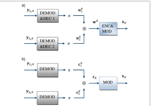
We study two relaying protocols: DMF relaying and DF relaying as shown in Figure 1. In DMF relaying, two receivers first demodulate the corresponding sig-nalsy1r,y2r to get the estimated codewordscr1,cr2. Then the estimated codewords are interleaved before being network-encoded to get cr = π(cr1) ⊕ π(cr2), where
π(.) denotes interleaving operations and⊕denotes bit-wise XOR operations. In DF relaying, two soft-input hard-output (SIHO) decoders decode y1r,y2r to get the estimated information messagesur1,ur2. Note that errors may occur during the decoding process at the relay, i.e.,
the estimated messages are different from the messages transmitted from the sources. Unlike [12], which only forwards estimated bits with reliability above a certain threshold, we always forward the estimated bits with or without decoding errors (error channel model). How-ever, the receiver will make use of the knowledge of the error probability at the relay. A network encoder encodes the interleaved estimated bitsπ(ur1),π(ur2)to get the network-coded information messageswr = π(ur1)⊕
π(ur
2). Then, a channel encoder encodes wr to get the codewordcr, which is then mapped into the modulated signalxr. The signal received at BS from the sources, at R from the sources, and at BS from R are given, respectively, as follows:
⎧ ⎨ ⎩
yjd =EsjdHjdxj+n, j=1, 2
yjr =EsjrHjrxj+n, j=1, 2
yrd =√EsrHrdxr+n,
(1)
where Esjd is the energy of the signal received at the destination from MSj, Esjr is the energy of the signal received at the relay from the MSj,Esr is the energy of the signal received at the destination from the relay. These
DEMOD
&DEC 1
DEMOD
&DEC 2
⊕
ENC&
MOD
a)
DEMOD
DEMOD
⊕
MOD
b)
quantities include the path loss effect;Hjd, Hjr, andHrd are Rayleigh fading coefficient matrices of source-to-relay channels and relay-to-destination channels, respectively, withE[||H(.)||2]= 1. For the sake of simplicity, we use matrix notation H(.) for all fading scenarios considered in this paper. Therefore, the structure of the matrixH(.) depends on the fading scenario. Three fading channel sce-narios are investigated: (1) fully interleaved fading, where H(.)=diag(h0,. . .,hN), withN =N/M, is the length of
x(.); (2)F-block fading, where the number of channel gains in one codeword is equal to F, the channel coefficient matrix is of the formH(.)=diag(h1,h2,. . .,hF)⊗I(N/F), with ⊗ denoting the Kronecker product, I(n) being an identity matrix; and (3) quasi-static fading, where we have H(.) = h0×I(N). Furthermore,n(index is ignored for simplicity) is the noise vector whose components are cir-cularly symmetric zero-mean complex Gaussian random variables with power spectrum density equal toσn2,nk ∼
CN(0,σn2).
3 Channel estimation and modulation metric computation
This section describes the computation of modulation metrics for both perfect and imperfect CSI as well as how channel estimation for imperfect CSI is performed. These metrics will be used in the next subsections to implement the proposed decoders.
3.1 Perfect CSI
For simplicity, we drop the channel indexes in our nota-tion. Letxandy=Hx + nbe transmitted and received signals of a generic channel link. The demodulation met-ric of thekth symbol is computed, given the channel gain
hk(corresponding to thekth symbol), as follows:
DFCSI(xk,yk|hk)=log(σn2)+
where Es(.) is the energy at the destination of the signal received from the sources or from the relay.
Let Ck = {ck1,ck2,. . .,ckM} be the kth data symbol, which contains M coded bits, associated to symbol xk, belonging to the constellation set. The cardinality of is equal to 2M. The a posteriori probability (APP) of the
lth bit,l=1,. . .,Min thekth symbol after demodulating
whereλis a normalization factor that satisfies the condi-tionPFCSI(ckl =1)+PFCSI(ckl=0)=1. Then, the LLR of
Lckl is sent to the JNCD decoder and is processed as described in the next sections.
3.2 Imperfect CSI
As far as the imperfect CSI case is concerned, we restrict our attention to only block fading channels withFblocks and quasi-static fading withF = 1. The reason is that channel estimation is assumed to be obtained via a pilot-based approach for [23], which is clearly not compatible with fully interleaved Rayleigh fading. The channel gain is assumed to be constant over one block and is assumed to change independently from block to block. In our set-ting, a codeword coversFblocks, and the relay estimates the error probability of the whole codeword based on the knowledge of the channel gains of all blocks (see section 5 below). These channel gains are estimated via a pilot mes-sage, which is inserted at the beginning of each block, and transmitted via BPSK modulation.
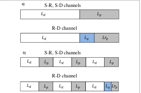
LetLdbe the length in bits of the coded data part and
Lp the length of the overhead. As far as the source-relay links and the source-destination links are concerned, each block consists ofLd/M data symbols andLp pilot sym-bols. As far as the relay-destination link is concerned, the relay also transmits to the destination a quantized version of its decoding error probability which is transmitted in the same way as the pilot bits. In this case, the overhead of lengthLp consists in the number of symbolsLq used for transmitting this error probability (quantization pre-cision), plus the pilot sequence which is thus reduced to
Lrp =Lp−Lq. In block fading environment withF >1, the error probability is concerned with the whole code-word, thus only one block of the R-BS channel is used to transmit this quantized error probability. The packet structure is sketched in Figure 2. Note that pilot and quan-tization bits are assumed to be binary modulated in order to make the decoding process more robust.
We define a channel rate Rcas the ratio of the infor-mation bits over the packet length in one channel use (in contrast with standard definition, we include the overhead bits). IfF=1 andLd =N, we have
S-R, S-D channels
R-D channel
a)
S-R, S-D channels
R-D channel
b)
Figure 2Packet structure for imperfect CSI case: (a)F=1block fading channel, (b)F=3block fading channel.
The difference of the channel rates forF =1 andF >1 is negligible and can be ignored in practice. For exam-ple, for the parameters used in the simulation section, the actual rates forF=1 andF=4 are respectively 0.476 and 0.417. In this paper, block fading channels withF >4 are not considered.
For simplicity, we drop MS and R indexes in our nota-tion. The channel estimation of the generic link works as follows. Each transmission block first consists in the pilot messagexpfollowed by the data messagexd. The power of pilot symbols and data symbols are equal. The corre-sponding received signalsypandydare of a form as in (1) with only one difference that the channel coefficienthin this case is a scale instead of a vector as in (1).
Note that the use of pilot message and its placement can be optimized via a cross-layer pilot design [24]. In this paper, since we just focus on the impact of imperfect CSI on performance of iterative decoding algorithms, a ran-dom sequence is used for pilot message, which obviously is a sub-optimal solution.
A maximum likelihood (ML) estimator is employed. The estimated channel gain is given as [23] hˆ = x∗
pyp(x∗pxp)−1, where(.)∗denotes the transpose conjugate operator,(.)−1, denotes the matrix inverse operator. The
channel estimation error ish˜=h− ˆh. Employing the mis-match demodulator, the estimated channel coefficienthˆis used as the correct oneh. The modulation metric is then computed as follows:
DPCSI(xk,yk|ˆh)=log(σn2)+
|yk−
Es(.)hxˆ k|2
σ2
n
.
LetCk = {ck1,ck2,. . .,ckM}be thekth data symbol asso-ciated to symbolxk. Thea posterioriprobability of thelth bit,l=1,. . .,Min thekth symbol,ckl, after demodulation can be computed as follows:
PPCSI(ckl =1)=λ
xk∈,ckl=1 exp
−DPCSI(xk,yk|ˆh) ,
whereλ is a normalization factor such thatPPCSI(ckl = 1) +PPCSI(ckl = 0) = 1. The LLR demodulation out-put of the coded bitckl, Lckl is computed as in (2) with DPCSI(xk,yk|ˆh)is used instead ofDFCSI(xk,yk|h).
These LLR are then used by the JNCD decoder for further processing as described in the next sections.
error of the information bits, while the second algorithm works on possible decoding error of coded bits. The error probability of information and coded bits are denoted by Pebitand Pecode, respectively.
4.1 Proposed JNCD: Algorithm 1
The first algorithm is developed based on turbo-like decoding methods. To fully exploit the potential dis-tributed diversity provided by the relay, the destination needs to know the decoding error probability at the relay, which is estimated and transmitted by the relay as described in the previous section. After receiving three channel observations from the two sources and from the relay, along with the decoding error probability at the relay, the destination runs the algorithm as follows:
First, maximuma posterioriprobability (MAP) decod-ing is applied. Let c1ˆ ,c2ˆ , and cˆr be the soft outputs of the demodulators associated to MS1, MS2, and R, respectively. At the destination, the maximuma posteriori
probability decision rule is
u1k,u2k=arg max u1k,u2k
P[u1k,u2k|ˆc1,c2ˆ ,cˆr] , (3)
whereP[.] denotes probability andP[a|b] denotes proba-bility ofaconditioned onb.
The probability in (3) is the marginal probability of the whole codeword. With some algebra, (3) can be rewritten as follows: given the information messages, the received signals are independent. Thus, the righthand side of (4) simplifies to:
u2∼{u2k} u1∼{u2k},wr
P[c1ˆ |u1]P[c2ˆ |u2]P[cˆr|wr]P[wr|u1,u2] . (5)
The last term in (5) accounts for possible decoding errors at the relay. We note that this decoding error is on the information bits. The related error probability is denoted by Pebit and it is computed in the next section. We assume, for tractability, that the network-coded infor-mation bits are independent (a reasonable assumptions when interleavers at the relay are used). Thus, we have
P[wr]= Kk=1P[wrk]. This assumption leads to a subop-timal JNCD algorithm. In addition, since the transmitted information bits are independent, we haveP[wr|u1,u2]=
K
k=1P[wrk|u1k,u2k]. Letwk = u1k ⊕u2k be the correct network-coded bit. We note thatwis based on the code-book whilewris based on the actual estimate at the relay. As a result, the decoding error at the relay is determined byPr[wrk|wk]. The decision rule in (5) becomes
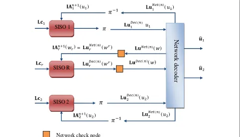
The block diagram of the proposed JNCD algorithm is illustrated in Figure 3. The algorithm consists of three SISO decoders for the two sources and the single relay, as well as one network decoder. There is also a decod-ing check node between the SISO decoder for the relay and the network decoder, which controls the uncertainty of the decoding process at the relay. LetLuNet1 (.),LuNet2 (.), andLuNet(.)be the extrinsic LLRs of the information bits sent by the network decoder to SISO decoder 1, SISO decoder 2, and SISO decoder R, respectively. Also, let LuDec
1 (.),LuDec2 (.), and LuDec(.)be the extrinsic LLRs of the information bits that reach the network decoder from SISO decoder 1, SISO decoder 2, and SISO decoder R, respectively. Furthermore, let LuDecr (.) be the extrinsic LLRs of the information bits sent from SISO decoder R to the decoding check node, andLuNetr (.)be the extrinsic LLRs of the information bits that reach the SISO decoder R from the decoding check node.
The proposed iterative decoding algorithm works by exchanging extrinsic information between the SISO decoders and the network decoder. It consists in the following steps:
Step 0. (Setup) LetLc1,Lc2, andLcrbe the LLRs of code-wordsc1ˆ ,c2ˆ , andcˆr, respectively, which are the outputs of the demodulators described in section 2. Thekth element ofLcj, j=1, 2,ris computed as in section 3.
Step 1. (Channel decoding) At thenth iteration, the SISO decoder j, j = 1, 2, and SISO decoder R run the BCJR algorithm [25], as follows:Input: extrinsic information of coded bitsLcj, j = 1, 2,randa prioriinformationIAnj,
Output: extrinsic of information bitsLuDec(j n)(uj), j = 1, 2, andLuDec(r n)(wr). The upper index(n)indicates the index iteration. In the first iteration, there is no a priori
(
)
(
)
( )
( )
(
)
( )
( )
( )(
)
(
) =
( )(
)
( )
(
)
( )
( )
( )(
)
Network decoder
Network check node
SISO 1
SISO R
SISO 2
Figure 3Diagram of the proposed JNCD algorithm 1.
Step 2. (Decoding errors are taken into account). The decoding check node updates the extrinsic of the esti-mated network-coded information bitsLuDec(r n)(wr)to get the extrinsic of correct network-coded information bits LuDec(n)(w) by taking into account the decoding error probabilityPebit. Let LuDec(n)r (wrk)and LuDec(n)(wk)be the
kth elements of LuDec(r n)(wr) and LuDec(n)(w), respec-tively, then
LuDec(n)(wk)=log
(1−Pebit)exp
LuDecr (n)(wrk) +Pebit
Pebitexp
LuDecr (n)(wrk) +1−Pebit .
(7)
Step 3. (Network decoding) The extrinsic of information bits LuDec(1 n)(u1), Lu2Dec(n)(u2), LuDec(n)(w) are input to the network decoder to outputLuNet(1 n)(u1),LuDec(2 n)(u2), LuNet(n)(w). Let LuNet(n)
1 (u1k), LuNet(2 n)(u2k), LuNet(n)(wk) be the kth element of LuNet(1 n)(u1), LuDec(2 n)(u2), LuNet(n)(w), respectively. The outputs of the network decoder are computed as follows:
LuNet1 (n)(u1k)=log
1+expLuDec2 (n)(u2k)+LuDec(n)(wk)
expLuDec2 (n)(u2k) +exp
LuDec(n)(w k)
,
LuNet2 (n)(u2k)=log
1+expLuDec1 (n)(u1k)+LuDec(n)(wk)
exp
LuDec1 (n)(u1k) +exp
LuDec(n)(wk) ,
LuNet(n)(wk)=log
1+expLuDec1 (n)(u1k)+LuDec2 (n)(u2k)
expLuDec1 (n)(u1k) +exp
LuDec2 (n)(u2k)
.
(8)
Step 4. (Decoding errors are taken into account) The decoding check node update LuNet(n)(w) to get LuNet(n)
r (wr) by taking into account the decoding error probability:
LuNet(r n)(wrk)=log(1−Pebit)exp
LuNet(n)(wk)
+Pebit Pebitexp
LuNet(n)(w k)
+1−Pebit .
(9)
Step 5. (Feedback) The extrinsic of information bits LuNet(n)
1 (u1), LuNet(2 n)(u2), and LuNet(n)(w) are feedback to SISO decoders 1,2, and R as a prioriinformation for the next iteration, as follows:IAn+1 1(u1) = LuNet(1 n)(u1); IAn+1
2 (u2)=LuNet(2 n)(u2);IArn+1(wr)=LuNet(r n)(wr).
Step 6. Repeat from Step 1.
4.2 Proposed JNCD: Algorithm 2
Pebit. On the other hand, the second proposed JNCD algo-rithm exploits the decoding error probability of the coded bits Pecode and performs network decoding first. After receiving three channel observations from the two sources and the single relay, along with the decoding error prob-ability Pecode, the destination applies the MAP decoding rule as follows [26]:
u1,u2=arg max u1,u2
P[u1,u2|ˆc1,c2ˆ ,cˆr]
∼arg max u1,u2
c1,c2
P[u1|c1]P[u2|c2]
×P[c1ˆ ,ˆc2,cˆr|c1,c2]
∼arg max u1,u2
c1,c2
P[u1|c1]P[u2|c2]
×P[c1ˆ |c1]P[c2ˆ |c2]× cr
P[cˆr|cr]P[cr|cr
c1⊕c2] ,
(10)
where cj, j = 1, 2 is the codeword generated from the information message uj; cr is the network-coded code-word;cr c1⊕c2 is thecorrect network-coded code-word;c1,2,ˆ r is the soft output of the demodulator related to sources 1, 2, and relay R. We note that the correct network-coded codewordcr is computed from the code-book, while the network-coded codewordcr = π(cr1)⊕
π(cr
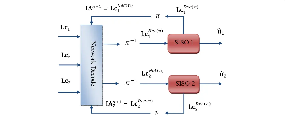
2)is computed from the estimated codewordcr1,cr2at the relay. The two first factors in (10) account for two channel decoders, and the other terms account for the network decoder. The last factor in (10) shows how error decoding on the coded bits at the relay, whose probabil-ity is Pecode, is taken into account by the decoder. The block diagram of this algorithm is sketched in Figure 4. The main difference between algorithm 1 and algorithm
2 is that in the latter case, network decoding is per-formed first. As a result, one channel decoder can be avoided in algorithm 2, which makes the receiver simpler to implement.
LetLc1,Lc2, andLcrbe LLR inputs for sources 1, 2, and relay R, respectively. Let LcNet1 andLcNet2 be the extrin-sic information outputs of the network decoder, andLcDec1 andLcDec2 be extrinsic information outputs of the coded bits of SISO decoder 1 and SISO decoder 2. Finally, letIA1 andIA2be thea prioriinformation (on coded bits) of the network decoder.
Algorithm 2 consists of following steps:
Step 0. (Setup) The three demodulators process the received signal to outputLc1,Lc2,Lcr. The kthelement of
Lcj, j=1, 2,ris computed as in Section 3.
A decoding check node updates Lcr by taking into account the decoding error probability at the relay, Pecode, to getLcr:
Lcrk=log(
1−Pecode)exp(Lcrk)+Pecode Pecode exp(Lcrk)+1−Pecode
, (11)
whereLcrkandLcrkare thekth elements ofLcr andLcr, respectively.
Step 1. (Network decoding) At thenth iteration, the net-work decoder decodesLc1,Lc2,Lcr, witha priori infor-mationIAn1andIAn2to output the extrinsic information of coded bitsLcNet(1 n)andLcNet(2 n). LetLc1k,Lc2k, andLcrkbe thekth elements ofLc1,Lc2, andLcr, respectively;LcNet(1k n) andLcNet(2k n) be thekth element ofLc1Net(n) andLcNet(2 n), respectively; and IAn1kand IAn2kbe thekth elements ofIAn1 andIAn2, respectively. Then
( ) ( )
Networ
k Decoder
( )
( )
=
( )=
( )SISO 1
SISO 2
LcNet(1k n))=Lc1k+log run the BCJR algorithm [25] as follows:Input: extrinsic information of coded bits LcNet(j n); the a priori extrin-sic of information bits is equal to 0. Output: extrinsic information of coded bitsLcDec(j n).
Step 3. (Feedback) The extrinsic information of coded bitsLcDec1 , LcDec2 is feedback to the network decoder as
a priori(of coded bits) information for the next iteration: IAn+1
j =LcDec(j n), j=1, 2.
Step 4. Repeat from Step 1.
5 Error probability estimation and quantization In order to apply the algorithms described in the previ-ous section, the destination must estimate Pebit=P[wr = u1⊕u2] and Pecode = P[cr = c1⊕c2]. In this section, we compute these probabilities. Let Pebit(j)=P[urj =uj] and Pecode(j) = P[crj = cj] , j = 1, 2 be the decod-ing error probability of information bits and coded bits, respectively, of the link from source MSj to the relay. We assume, for simplicity, that the network-encoded informa-tion bits and network-encoded coded bits are independent (a reasonable assumption if interleavers are used at the relay).
The decoding error probability at the relay, Pebit, can be computed as follows:
The first factor can be computed as follows:
P[wr=1|u1⊕u2=0]
where the expression in (13) is given by the definition of XOR network coding. The decoding error probability at the relay, Pecode, can be computed using similar steps as follows:
Pecode=P[cr =c1⊕c2] The first factor in (16) can be computed in the same manner as in (13) as follows:
respectively. For simplicity, we focus our attention on 16-QAM modulation, as used in our numerical examples.
5.1 Error estimation with perfect CSI: computation of PeF1,F4,code Full
5.1.1 Block Rayleigh fading F=1
In this case, the channels MSj-Rj = 1, 2 are Gaussian-distributed conditioned onhj. The symbol error probabil-ity of theMSj−Rlink for M-QAM modulation is ([27],
where Q(.) denotes the Q-function,hjis the channel gain, and Es is the symbol energy. Because each symbol error causes one coded bit error (Gray mapping and nearest neighbor approximation), then the error probability of coded bits of, for example, 16-QAM modulation can be estimated as follows:
where erfc(·)is related to the Q-function.
5.1.2 Block Rayleigh fading F=4
Lethj = [hh1, hj2, hj3, hj4] be the channel gain vector of link MSj-Rj= 1, 2. Because the components ofhjare independent, the error probability PeFcode4 (j) of 16-QAM modulation is estimated as the average over the vectorhj:
PeFcode4 (j)= 1
5.1.3 Fully-interleaved Rayleigh fading
The error probability of coded bits of link MSj-R over fully interleaved Rayleigh fading channel is computed by inte-grating over the distribution of the channel gains. Lethjbe channel gain, thenγ = |hj|2is exponentially distributed with mean equal to E[|hj|2]= 1. Therefore, the symbol error rate of link MSj-R with M-QAM modulation is:
PsymFull
The coded bit error probability of 16-QAM modulation is thus equal to:
PeFullcode(j)=PsymFullM(j)/√M
5.2 Error estimation with perfect CSI: computation of PeF1,F4,bit Full
The information bit error probability of convolutional codes conditioned on the channel vector can be computed as follows ([28], Equation 3.175):
Pebit≈
∞
d=df
β(d)Pc(d), (24)
where df is the minimum distance,β(d) is the distance spectrum of the convolutional code, andPc(d)is the prob-ability of choosing a wrong path in the trellis with distance
dfrom the correct path (usually the all-zero path).Pc(d) depends on the channel gains and is computed as follows.
5.2.1 Block Rayleigh fading channel withF=1
Let Pjc(d) be the conditional pairwise error probability related to the MSj-R channel. Since Gray mapping is used and the nearest neighbor approximation is assumed, each symbol error only causes one error on the coded bits. In addition, the coded bits are interleaved before being mapped into the constellation. Thus, the conditional pairwise error probability of the MSj-R link is
Pjc(d)=
By substituting (25) in (24), the bit error probability of the MSj-R link is estimated as follows:
PeFbit1(j)≈ 3
In our simulation results, df = 6 for the RSC code [1 15/13] and only two values ofdare used.
5.2.2 Block Rayleigh fading channel withF=4
Pcj(d)=
D
Pjc(d|D)p(D), (27)
where the pairwise error probability given the weight patternDis computed as [22]:
Pjc(d|D)= 3
and the distribution of the patternD is computed using combinatorial analysis:
whereCkndenotes a combination ofkelements of a set ofn
elements;Ns= N/log2(M)is the length of a signal;m= Ns/Fis the block’s length.
From (24), (27), and (28), the error probability reduces to:
5.2.3 Fully interleaved Rayleigh fading
The error probability of coded bits does not depend on the instantaneous channel gain but on the noise variance only. The pairwise error probability in fully interleaved fading channel can be obtained by integrating over the distribution of channel gains. Using [28], we get:
PeFullbit(j)= 3β(df)
5.3 Error estimation with imperfect perfect CSI
In the imperfect CSI case, we considerF =1 andF = 4. The error probabilities at the relay can be computed as in the perfect CSI case, except that the estimated channel gainhˆj, j=1, 2 is used instead of correct onehj.
5.4 Error quantization
To inform the destination about the decoding error prob-ability at the relay, the relay quantizes and sends it to the destination. Let v¯ be a q-bit quantized value ofv using uniform quantization functionQq(.):
¯ mitted over fading plus Gaussian noise to the destination. At the end of the channel estimation phase, the destina-tion recovers the decoding error probability at the relay from the noisy version of the transmitted quantized signal.
6 Numerical results: perfect CSI case
In this section, we study the performance of the pro-posed JNCD algorithms in various fading scenarios. For this perfect CSI case, assume that the receivers have per-fect knowledge of the one-hop links CSI. In addition, the destination is assumed to have full knowledge of the decoding error probability at the relay, Pebit and Pecode, which are estimated as described in the previous sections. We assume a symmetric network topology in which the distance from the sources to the destination is the same. The relay is located between sources and destination. The path loss has been chosen equal to 3.5 [29]. Unless stated for specific cases, the recursive convolutional code (RSC) [1 15/3] with rate 1/2 is used. 16-QAM is used as the modulation scheme. The number of iterations used to obtain our results is four since we have observed that the algorithms converge to the best performance in four iterations.
Both DF and DMF relaying protocols are studied. In par-ticular, three schemes are studied: (1) DF relaying with the proposed algorithm 1, namedDF Algo 1in the figure; (2) DF relaying with the proposed algorithm 2, namedDF Algo 2in the figure; (3) DMF relaying with the proposed algorithm 2, named DMF Algo 2in the figure. We note that algorithm 1 cannot be used with the DMF protocol because it performs network coding on the information bits. We also compare our algorithms with [18], which is denoted byRef. [Yune]in the figure. In addition, we denote byBlindthe scenario where the receiver has no informa-tion about the decoding error probability at the relay (it assumes perfect decoding at the relay) and byNon Coop-eration the conventional point-to-point communication scenario.
6.1 Effects of iterations
0 1 2 3 4 5 6 10−7
10−6 10−5 10−4 10−3 10−2 10−1 100
Fully−interleaved Rayleigh fading channels
EbNo (dB)
BER
DF, Algo 1, Blind DF, Algo 1, 1 iter DF, Algo 1, 4 iters DF, Algo 2, Blind DF, Algo 2, 1 iter DF, Algo 2, 4 iters DMF, Algo 2, Blind DMF, Algo 2, 1 iter Ref. [Yune] DMF, Algo 2, 4 iters
a)
0 2 4 6 8 10 12
10−7 10−6 10−5 10−4 10−3 10−2 10−1 100
Block Rayleigh fading channels: F = 4
EbNo (dB)
BER
SNR−4 curve DF, Algo 1, Blind DF, Algo 1, 1 iter DF, Algo 1, 4 iters DF, Algo 2, Blind DF, Algo 2, 1 iter DF, Algo 2, 4 iters DMF, Algo 2, Blind DMF, Algo 2, 1 iter Ref. [Yune] DMF, Algo 2, 4 iters
b)
5 10 15 20 25
10−7 10−6 10−5 10−4 10−3 10−2 10−1
Quasi−static block Rayleigh fading channels: F = 1
EbNo (dB)
BER
SNR−2 curve DF, Algo 1, Blind DF, Algo 1, 1 iter DF, Algo 1, 4 iters DF, Algo 2, Blind DF, Algo 2, 1 iter DF, Algo 2, 4 iters DMF, Algo 2, Blind DMF, Algo 2, 1 iter Ref. [Yune] DMF, Algo 2, 4 iters
c)
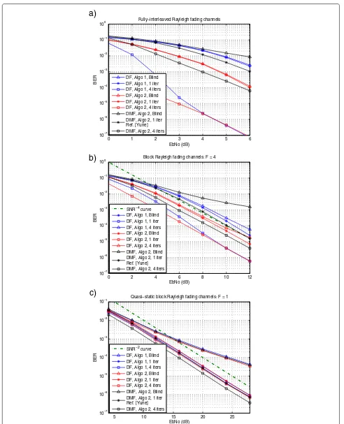
2 dB better than the algorithm 1 after one iteration. After four iterations, the two algorithms tend to have almost the same performance as SNR increases. (3) Compared to [18], the two proposed algorithms with four iterations and DF protocol significantly outperform.
Figure 5b shows the simulation results for block fading channel with F = 4. In addition, the theoretical curve SNR−4is plotted to provide some information about the achievable diversity order: (1) iterative decoding improves performance for both DF and DMF relaying. With four iterations, DF relaying with the proposed algorithm 1 gains about 3 dB and with the proposed algorithm 2, it gains about 2 dB at a BER equal to 10−4compared to the single iteration case. DMF relaying with algorithm 2 gains about 1 dB. (2) Compared to [18], after four iterations, algorithm 1 and algorithm 2 with DF relaying both gain about 3 dB at a BER equal to 10−4. With DMF relaying, the algorithm 2 with four iterations gains about 1 dB at a BER equal to 10−4. (3) For both DF and DMF relaying, the receiver loses the diversity order if it has no information about the decoding error probability.
We note that in Figure 5b, the proposed algorithms have diversity order equal to 4 ifF =4. The reason is that the diversity gaindHof a convolutional code in aF-block fad-ing channel withM-QAM modulation is upper bound by [22]:
dH ≤ F(1− R
M +1,
wherexdenotes the largest integer no greater thanx,R
is the code rate in bits/symbol. In our setup, we haveR=2
bits/symbol and 16-QAM. Thus, we get dH ≤ 3. It is shown from the simulation that the actual diversity order of the code [1 15/13] is 2 in the SNR range of interest. Therefore, it is reasonable that in the MARC, the relay provides a better diversity gain.
Figure 5c shows simulation results for the quasi-static fading channel with F = 1. In addition, the theoreti-cal curve SNR−2 is plotted as a diversity reference. It is shown in the figure that (1) if the receiver is not informed about the decoding error probability at the relay, the per-formance is dramatically decreased and it loses diversity order; (2) iterative decoding brings a little gain in both algorithms. Algorithm 2 with four iterations gains about 0.8 dB over the one-iteration case, while algorithm 1 with four iterations gains about 0.5 dB over the one-iteration case; and (3) DMF with algorithm 2 is slightly better than DF with both algorithms.
Consider three fading channels, algorithm 2 is recom-mended because of its low complexity compared with algorithm 1. With quasi-static block fading scenario, DMF relaying is recommended. In this case, channel decoding at the relay does not improve the system performance. In generalF-block fading channels, DF relaying should be used.
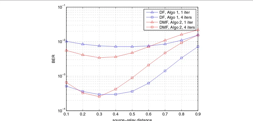
6.2 Effects of location of the relay
Figure 6 shows the effects of relay’s position on the perfor-mance of the proposed algorithms inF=4 block Rayleigh fading channels. The horizonal axis presents the normal-ized source-relay distance when source-destination dis-tance is 1. The system operates at EbNo = 6 dB. It is shown
0.1 0.2 0.3 0.4 0.5 0.6 0.7 0.8 0.9 10−4
10−3 10−2 10−1
source−relay distance
BER
DF, Algo 1, 1 iter DF, Algo 1, 4 iters DMF, Algo 2, 1 iter DMF, Algo 2, 4 iters
that the system performance is degraded when the relay move close to the destination. It is because in this case, the possible errors at the relay are so high. The system achieves the best performance when the relay is close to the source. In addition, the optimal location for DMF is closer to the source than that for DF. Since DMF does not perform channel decoding, it needs the source-relay links to be good enough for effective cooperation.
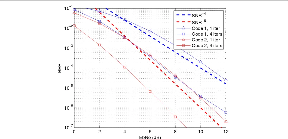
6.3 Effects of the channel code
Figure 7 presents the performance of the proposed algorithm 1 with DF in F = 4 block Rayleigh fading scenario and the relay locates at the middle between the sources and the relay. The destination has full knowledge of the decoding error at the relay. Two channel codes are compared. Code 1: RSC [1 15/13] with rate 1/2 and Code 2: RSC [1 15/13 17/13] with rate 1/3. Obviously, the Code 2 with higher error-correction capability provides better performance than the Code 1. In addition, the MARC with Code 2 achieves diversity order 6 while the MARC with Code 1 achieves diversity order 4 in the SNR region of interest. This is because in F = 4 block fading, the Code 1 can only achieve diversity order 2 while the Code 2 provides diversity order 3.
7 Numerical results: imperfect CSI case
This section evaluates the impact of imperfect CSI and quantization error on the performance of the proposed algorithms. The two case studies withF=1 andF =4 are investigated. The relay is located at the middle between
the sources and the destination. The RSC [1 15/13] is cho-sen as in the previous section and 16-QAM is used. The ML estimator is used for channel estimation. Because the performance of algorithm 2 with DF and DMF relaying is almost the same, we only study algorithm 2 with DMF relaying in this section. Then, in this section, algorithm 1 is linked to DF relaying and algorithm 2 is linked to DMF relaying. In the figures,Full CSI denotes the case when the receivers (relay and destination) have perfect chan-nel state information of the one-hop links. On the other hand,Full Pedenotes the case when the destination has full knowledge of the decoding error probability at the relay.
Intensive simulations show that iterative decoding only provides coding gain if the receivers have enough accurate CSI and possible decoding errors. However, concerning realistic imperfect CSI systems where the total number of overhead symbols is not too large, we focus on only sepa-rate decoding (one iteration) for block fadings (F =1 and
F=4) in what follows.
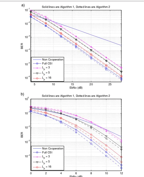
7.1 Effects of pilot length
Figure 8 shows the effect of pilot length assuming Full-Pe for both quasi-static andF =4 block fading channels. Both algorithms have the same performance trend as a function of number of pilot symbols. It is shown that pilot length only affects the coding gain, and it does not change the diversity order of the system in the SNR range of inter-est. In addition, 16-symbol pilot curve is about 1-dB worse than the full CSI curve (at a BER equal to 10−4).
0 2 4 6 8 10 12 10−7
10−6 10−5 10−4 10−3 10−2 10−1
EbNo (dB)
BER
SNR−4 SNR−6 Code 1, 1 iter Code 1, 4 iters Code 2, 1 iter Code 2, 4 iters
5 10 15 20 25 10−6
10−5 10−4 10−3 10−2 10−1
Solid lines are Algorithm 1, Dotted lines are Algorithm 2
EbNo (dB)
BER
Non Cooperation Full CSI
L p = 3 L
p = 5
L p = 16
a)
0 2 4 6 8 10 12
10−4 10−3 10−2 10−1 100
Solid lines are Algorithm 1, Dotted lines are Algorithm 2
EbNo (dB)
BER
Non Cooperation Full CSI
L p = 3
L p = 5
Lp = 16
b)
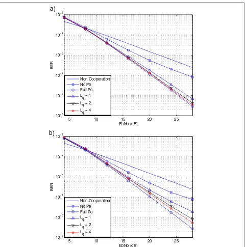
7.2 Effects of quantization
Figure 9 illustrates the effect of quantization by assum-ing five pilot symbols andF = 1. We note that the total overhead symbols (pilot symbols and quantization sym-bols) are five, the pilot symbols on relay-destination link is less than five. It is observed that if the BER at the relay is not taken into account by the decoder at des-tination, it loses both coding gain and diversity order. Furthermore, the quantization level,Lq, affects both per-formance and diversity order. In both algorithms,Lq = 4
bits quantization ( Lp = 1 symbol for relay-destination link) can achieve almost same performance as the full Pe case. It implies that the system BER is more sensitive to the quantization accuracy than the pilot length.
Figure 10 shows the effect of quantization with per-fect CSI and F = 4. Similar conclusions as above are derived. The quantization level affects both diversity order and coding gain. The quantization level has small effect to the algorithm 1 and it achieves almost same perfor-mance as full Pe case in the observing SNR range. This
5 10 15 20 25 10−6
10−5 10−4 10−3 10−2 10−1
EbNo (dB)
BER
Non Cooperation No Pe
Full Pe L
q = 1 Lq = 2
Lq = 4
a)
5 10 15 20 25 10−6
10−5 10−4 10−3 10−2 10−1
EbNo (dB)
BER
Non Cooperation No Pe
Full Pe Lq = 1
L q = 2 Lq = 4
b)
0 2 4 6 8 10 12 10−4
10−3 10−2 10−1 100
EbNo (dB)
BER
Non Cooperation Full Pe
L q = 1 Lq = 3
Lq = 6
a)
0 2 4 6 8 10 12 10−4
10−3 10−2 10−1 100
EbNo (dB)
BER
Non Cooperation Full Pe
L q = 1 L
q = 3 Lq = 6
b)
Figure 10Effects of quantization levelLqon performance of proposed algorithms in block fadingF=4with perfect CSI.a)The proposed algorithm 1.b)The proposed algorithm 2.
is because the algorithm 1 performs channel decoding at the relay and the possible decoding errors are negligible in this situation. Unlike algorithm 1, the performance of the algorithm 2 significantly degrades with quantized errors, even whenLq = 6 bits are used. This is because of two following reasons: (1) the algorithm 2 employs DMF relay-ing, which results in high errors at the relay and (2) the decoding errors at the relay is computed as the average over four channels, which is not accurate for individual independent channels.
8 Conclusion
In this paper, we have studied the performance of the multiple access relay channel with binary Network Coding and JNCD at the destination in practical situa-tions. Decode and Forward and Demodulate and Forward relaying strategies are investigated. Our results show that iterative Joint Network and Channel Decoding provides better performance than separate network channel decod-ing only if the destination has enough CSI and knowledge of the decoding error probability at the relay. This gain increases with the number of fading blocks per codeword. It is also shown that the number of pilot symbols mostly affects the coding gain of the system with a negligible impact on the diversity order, at least for the SNR range of interest. Finally, it is shown that CSI quantization errors affect both coding gain and diversity order. In general, representing the BER at the relay using 6-bit quantiza-tion is sufficient for both DMF relaying and DF relaying. The proposed iterative decoding algorithms can be eas-ily extended to frequency selective fading scenarios, e.g., OFDM systems.
Competing interests
The authors declare that they have no competing interests.
Acknowledgements
The research work is supported in part by the European Commission under the auspices of the FP7-PEOPLE MITN-CROSS FIRE project (Grant 317126) and in part by the European Commission in the framework of the FP7 Network of Excellence in Wireless COMmunications NEWCOM# (Grant agreement no. 318306).
Received: 8 April 2013 Accepted: 23 October 2013 Published: 11 November 2013
References
1. A Sendonaris, E Erkip, B Aazhang, User cooperation diversity - Part I: system description. IEEE Trans. Commun.51(11), 1927–1938 (2003) 2. JN Laneman, DNC Tse, GW Wornell, Cooperative diversity in wireless
networks: Efficient protocols and outage behavior. Inform. Theory, IEEE Trans.50(12), 3062–3080 (2004)
3. R Ahlswede, C Ning, SYR Li, RW Yeung, Network information flow. Inform. Theory, IEEE Trans.46(4), 1204–1216 (2000)
4. M Renzo, L Iwaza, M Kieffer, P Duhamel, K Agha, Robust wireless network coding–an overview, inLecture Notes of the Institute for Computer Sciences. Social Informatics and Telecommunications Engineering,Vol. 45 (Springer, Berlin Heidelberg, 2010), pp. 685–698
5. Y Sichao, R Koetter, Network coding over a noisy relay : a belief propagation approach. in theIEEE International Symposium on Information Theory, ISIT 2007. Nice, 24–29 June 2007
6. DH Woldegebreal, H Karl, Multiple-access relay channel with network coding and non-ideal source-relay channels in the4th International Symposium on Wireless Communication Systems, ISWCS 2007. Trondheim, 17–19 October 2007
7. C Hausl, P Dupraz,Joint network-channel coding for the multiple-access relay channel in the 2006 3rd Annual IEEE Communications Society on Sensor and Ad Hoc Communications and Networks, SECON ’06.Reston, 25–28 September Vol. 3 (IEEE Piscataway 2006), pp. 817–822
8. ZA Polgar, MP Stef, V Bota, Network and channel coded cooperation algorithms for cellular networks in theIEEE 69th Vehicular Technology Conference 2009, VTC Spring. Barcelona, 26–29 April, 2009
9. L Yonghui, B Vucetic, TF Wong, M Dohler, Distributed turbo coding with soft information relaying in multihop relay networks. Select. Areas Commun., IEEE J.24(11), 2040–2050 (2006)
10. P Weitkemper, D Wuebben, V Kuehn, KD Kammeyer, Soft information relaying for wireless networks with error- prone source-relay link, in the 7th International ITG Conference on Source and Channel Coding (SCC). Ulm, 14–16 January 2008
11. HH Sneesens, L Vandendorpe, Soft decode and forward improves cooperative communications, in the1st IEEE International Workshop on Computational Advances in Multi-Sensor Adaptive Processing. Puerto Vallarta, 13–15 December, 2005
12. Al-G Habian, A Ghrayeb, M Hasna, Controlling error propagation in network-coded cooperative wireless systems, in theIEEE International Conference on Communications, ICC ‘09.Dresden, 14-16 June 2009, pp. 1–6 13. N Sinh Le Hong, A Ghrayeb, Al-G Habian, M Hasna, Mitigating error
propagation in two-way relay channels with network coding. Wireless Commun. IEEE Trans.9(11), 3380–3390 (2010)
14. A Bletsas, A Khisti, DP Reed, A Lippman, A simple cooperative diversity method based on network path selection. IEEE J. Select Areas Commun.
24(3), 659–672 (2006)
15. X Ming, T Aulin, Optimal decoding and performance analysis of a noisy channel network with network coding. Commun, IEEE Trans.57(5), 1402–1412 (2009)
16. HH Sneessens, J Louveaux, L Vandendorpe, Turbo-coded decode-and-forward strategy resilient to relay errors, in theIEEE International Conference on Acoustics, Speech and Signal Processing, ICASSP 2008. Las Vegas, 30 March - 4 April 2008
17. K Lee, L Hanzo, MIMO-assisted hard versus soft decoding-and-forwarding for network coding aided relaying systems. Wireless Commun. IEEE Trans.
8, 376–385 (2009)
18. T Yune, D Kim, G Im, Opportunistic network-coded cooperative transmission with demodulate-and-forward protocol in wireless channels. Commun, IEEE Trans.PP(99), 1–5 (2011)
19. TT Kim, G Caire, M Skoglund, Decode-and-forward relaying with quantized channel state feedback: an outage exponent analysis. Inform. Theory, IEEE Trans.54(10), 4548–4564 (2008)
20. D Zhiguo, KK Leung, Impact of imperfect channel state information on bi-directional communications with relay selection. Signal Process IEEE Trans.59(11), 5657–5662 (2011)
21. B Nazer, M Gastpar, Compute-and-forward: Harnessing interference with structured codes, inIEEE International Symposium on Information Theory, 2008. ISIT 2008. Toronto, 6–11 July 2008
22. R Knopp, PA Humblet, On coding for block fading channels. Inform. Theory IEEE Trans.46, 189–205 (2000)
23. JK Cavers, An analysis of pilot symbol assisted modulation for Rayleigh fading channels [mobile radio]. Vehicular Technol. IEEE Trans.40(4), 686–693 (1991)
24. T Lang, BM Sadler, M Dong, Pilot-assisted wireless transmissions: general model, design criteria, and signal processing. Signal Process Mag. IEEE.
21(6), 12–25 (2004)
25. L Bahl, J Cocke, F Jelinek, J Raviv, Optimal decoding of linear codes for minimizing symbol error rate (Corresp.) Inform. Theory IEEE Trans.20(2), 284–287 (1974)
26. XT Vu, M Di Renzo, P Duhamel, Optimal and low-complexity iterative joint network/channel decoding for the multiple-access relay channel. in the 2011 IEEE International Conference on Acoustics Speech and Signal Processing (ICASSP 2011). Prague, 22–27 May 2011
27. JG Proakis,Digit Communications.McGraw-Hill series in electrical and computer engineering, 4th edition (McGraw-Hill, Boston, 2001). [00025305 John G. Proakis. ill.]
28. A Glavieux,Channel Coding in Communication Networks: From Theory to Turbo Codes(Wiley, New York, 2007)
29. Z Ren, G Wang, Q Chen, H Li, Modelling and simulation of Rayleigh fading, path loss, and shadowing fading for wireless mobile networks. Simulation Modell. Pract. Theory.19(2), 626–637 (2011)
doi:10.1186/1687-6180-2013-170
Cite this article as:Vuet al.:Multiple-access relaying with network coding: