F U L L P A P E R
Open Access
Seismic moment and volume change of a
spherical source
Hiroyuki Kumagai
1*, Yuta Maeda
1, Mie Ichihara
2, Nobuki Kame
2and Tetsuya Kusakabe
2Abstract
A spherical source, one of the simplest seismic sources, has been represented in various ways in the literature. These representations include a spherical source with outward radial expansion (S1), a spherical crack source with outward and inward crack wall motions along the spherical surface (S2), an isotropic source represented by three mutually perpendicular vector dipoles (S3) or three mutually perpendicular tensile cracks (S4), and a spherical source undergoing a transformational expansion (S5). We systematically examined these sources and their static displacement fields to clarify how these representations are mutually related. We also considered the sources in a bimaterial medium, in which the source material is different from the surrounding medium, as a model of a magma or hydrothermal reservoir. Our examinations show that the source volume change of a spherical source (S1) (actual volume) can be uniquely determined from the seismic moment of an isotropic source (S3) regardless of our assumption of the source medium and that the actual volume of S1 is related to the seismic moment of S3 through the equivalence of the displacement fields due to these two sources. The seismic moment of S3 is also related through another equation to the source volume change of three tensile cracks (S4), which is equal to the source volume changes defined in S2 and S5. This relation has different forms, depending on the source medium and source process. This study provides a unified view for quantifying a spherical source using the seismic moment of an isotropic source determined from waveform inversion analysis.
Keywords: Volume source; Isotropic source; Source representation; Volcano seismology; Waveform inversion
Background
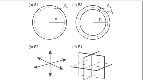
Spherical and cylindrical volume changes have been considered as sources of volcano seismic signals (e.g., Kanamori et al. 1980; Fukuyama and Takeo 1987; Uhira and Takeo 1994; Dreger et al. 2000; Legrand et al. 2000; Tameguri et al. 2002; Ohminato et al. 2006; Maeda and Takeo 2011; Kumagai et al. 2011). Although a spherical source is one of the simplest seismic sources, there are var-ious ways to represent it. These representations include a spherical source with outward radial expansion (e.g., Mogi 1958) (S1, Figure 1a), a spherical crack source of Müller (2001) (S2, Figure 1b), an isotropic source repre-sented by three mutually perpendicular vector dipoles (S3, Figure 1c) or three mutually perpendicular tensile cracks (S4, Figure 1d), and a spherical source undergoing a
trans-*Correspondence: [email protected]
1Graduate School of Environmental Studies, Nagoya University, Furo-cho, Chikusa-ku, Nagoya 464-8601, Japan
Full list of author information is available at the end of the article
formational expansion based on the concept of imagi-nary cutting, straining, and welding operations of Eshelby (1957) as introduced by Aki and richards (2002), which we call an Eshelby spherical source (S5, Figure 2a).
Using these representations, the seismic moment of a spherical source has been defined in two different ways (Müller 2001; Richards and Kim 2005). The two defini-tions are
M0=(λ+2μ)Vs, (1)
M0=(λ+2μ/3)Vf, (2)
where λand μare Lamé’s constants and Vs andVf are two different definitions of source volume changes (see below). The recent volcano seismology literature has used Equation 1 (e.g., Kawakatsu and Yamamoto 2007; Kumagai 2009; Chouet 2013), whereas earlier studies gen-erally used Equation 2 (e.g., Chouet 1996; Julian et al. 1998; Dreger et al. 2000; Nishimura and Iguchi 2011).
According to Kawakatsu and Yamamoto (2007), the volume change in Equation 2 (Vf) corresponds to the
d
sΔ
sR
R
Δ
s(a) S1
(b) S2
(c) S3
(d) S4
Figure 1Source representations.(a)A spherical source with purely outward radial expansion ofs(S1),(b)a spherical crack source with outward and inward displacements (sandds, respectively) along the spherical surface (S2),(c)an isotropic source with three mutually perpendicular vector dipoles (S3), and(d)a superposition of three mutually perpendicular tensile cracks (S4).
stress-free volume, introduced by Eshelby (1957), whereas the actual volume in Equation 1 (Vs) may be smaller than the stress-free volume because of the confining pressure of the surrounding medium. Kawakatsu and Yamamoto (2007) also noted that the actual volume cor-responds to the volume change used in the Mogi model (e.g., Mogi 1958).
Müller (2001) noted that the discrepancy between Equations 1 and 2 could not be resolved, and he inter-preted these two forms to correspond to the limits of the actual volume of the source. Wielandt (2003) discussed the discrepancy and noted that the source volume change depends on the source geometry. Richards and Kim (2005) argued that each relationship is based on a different defi-nition of volume changes at the source and that Equation 1 is preferred for characterizing underground explosions.
It is not clear why a spherical source has been repre-sented in different ways and how these representations, including the two seismic moment equations, are mutu-ally related. In Eshelby’s operations and Müller’s spherical crack, the source material is assumed to be the same as the surrounding medium. In volcanic regions, sources
may be filled with magmatic or hydrothermal fluids. No examinations have been made on a spherical source in such bimaterial media, although the source representation of fault slip on a bimaterial interface has been discussed in various studies (e.g., Ampuero and Dahlen 2005).
In this paper, we first review the spherical source rep-resentations mentioned above and then derive the static displacement fields due to these sources in an infinite medium and in a half-space. We compare the analytical forms of these displacements to clarify the relation-ships among these representations. We further exam-ine a spherical source in a bimaterial medium, which is of fundamental importance as a model of a magma or hydrothermal reservoir.
Methods
Source representations
Müller (2001) proposed to define a spherical source in terms of the outward crack wall motion of a spherical crack. Let us first define a spherical crack source (S2). We consider the moment density tensor of a tensile crack with normal direction(θ,φ)(Figure 3a):
m(θ,φ)=Ds ⎛ ⎜ ⎝
λ+2μsin2θcos2φ 2μsin2θsinφcosφ 2μsinθcosθcosφ
2μsin2θsinφcosφ λ+2μsin2θsin2φ 2μsinθcosθsinφ
2μsinθcosθcosφ 2μsinθcosθsinφ λ+2μcos2θ ⎞ ⎟
Δ
a
P
(a) S5
(b) S6
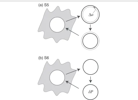
Figure 2Spherical source with stress-free strain and strain-free stress.(a)Schematic view of a spherical source undergoing a transformational expansion (S5) based on imaginary cutting, straining, and welding operations of Eshelby (1957).(b)A spherical source in which a strain-free stress or pressure (δP) is applied to the removed source volume (S6) (see text for details).
where Ds is the displacement discontinuity of a tensile crack (e.g., Chouet 1996). We consider a spherical crack surface with radiusRwhere a constant radial displacement discontinuityDs = (ds +s) occurs (Figure 1b). Here, the inner wall of the crack moves inward byds, and the outer wall moves outward bys. The moment tensor of the spherical crack source can be obtained by integrating the moment density tensor of the tensile crack over the surface with radiusR(Figure 1b):
M =
2π
0 π
0
m(θ,φ)R2sinθdθdφ,
= VD ⎛
⎝λ+20μ/3 λ+02μ/3 00
0 0 λ+2μ/3
⎞ ⎠, (4)
whereVDis the volume given as
VD=4πR2Ds=4πR2(ds+s). (5)
By solving the elastostatic boundary-value problem (see Subsection ‘Displacement fields’), we obtain
Vs
VD =
λ+2μ/3
λ+2μ , (6)
whereVs=4πR2s.
An isotropic source is defined as three mutually per-pendicular vector dipoles (S3, Figure 1c), of which the moment tensor is given as
M=MIso0 ⎛ ⎜ ⎝
1 0 0
0 1 0
0 0 1
⎞ ⎟
⎠, (7)
whereMIso0 is the seismic moment for an isotropic source. The three mutually perpendicular vector dipoles can be represented as the superposition of three mutually per-pendicular tensile cracks (S4, Figure 1d). In such a case, M0Isocan be defined as
x
2x
3θ
φ
(a)
x
1R
r
θ
(b)
x
3x
1-c
d
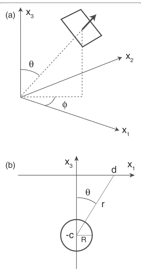
Figure 3Source coordinates for(a)a crack and(b)a spherical source in a half-space.
Here,Vi=3Vc, whereVcis the incremental change in the volume of each crack.
Finally, we consider an Eshelby spherical source follow-ing Aki and richards (2002) (S5, Figure 2a). A spherical volume with radius R removed from its surroundings expands toR+awith stress-free volumetric strain. We apply the surface traction that will restore the volume source to its original radius R, put the volume back in its hole, and weld the material across the cut. We release the applied traction, which results in the source volume expanding to R+ s. The volume defined as Vf = 4πR2ais the stress-free volume, and the volume defined
as Vs = 4πR2s is the actual volume or Mogi vol-ume. We define the seismic moment using the stress-free volume as
M0=(λ+2μ/3)Vf, (9)
and the seismic moment using the Mogi volume may be given as
M0=(λ+2μ)Vs. (10)
Displacement fields
Let us consider the static displacement fields due to each of the described sources. For the spherical source (S1), spherical crack source (S2), and Eshelby spherical source (S5), the displacement fields in an infinite medium are described by the following static equilibrium equation:
∂2ur ∂r2 +
2 r
∂ur ∂r −
2
r2ur=0, (11)
whereuris the radial displacement. We denote the regions inside and outside the sphere with radiusRas regions 1 and 2, respectively. Equation 11 has two solutions:ur=Ar andur = B/r2, whereAandBare constants. The former is the interior solution for region 1(r≤R), and the latter is the exterior solution for region 2(r≥R).
Spherical source
We first consider the spherical source (S1). If the pres-sure in the spherical source increases byP, the spherical source surface moves outward bysatr= R. Then, the boundary conditions atr=Rare given as
uer=s (12)
σrre = −P, (13)
where uer andσrre are the radial displacement and radial stress in region 2, respectively. Using these boundary con-ditions and the exterior solutionur = B/r2, we find that
P=4μs
R, (14)
and
uer= Vs
4πr2, (15)
whereVs=4πR2s.
Following Sezawa (1931), we consider the spherical source in a half-space (Figure 3b). The radial displacement on the free surface at distanceris given as
uer= (λ+2μ) 2μ(λ+μ)
R3P
r2 , (16)
= (λ+2μ) 2π(λ+μ)
Vs
If we assumeλ = μ, the vertical and radial components foruerin cylindrical coordinates are given as
uercosθ = 3R
respectively, where c is the source depth and d is the horizontal source distance (Figure 3b). Equations 18 and 19 represent the displacement field of the Mogi model (Mogi 1958).
Comparing Equation 17 for a half-space with
Equation 15 for an infinite medium, we find that these two equations differ by a factor of 2(λ+2μ)/(λ+μ)(Figure 4a). For this consideration, we usedVs =4πR2s, in which neither the stress-free volume nor Eshelby’s operations are introduced.
Spherical crack source
Next, we consider the spherical crack source (S2) of Müller (2001) in an infinite medium. The boundary condi-tions atr=Rare
r andσrri are the radial displacement and radial stress in region 1, respectively. Then, Müller (2001) obtained
We next consider the displacement field due to an isotropic source represented by three vector dipoles (S3). The static displacement field due to the moment tensor Mpqis given as
whereγiis the directional cosine andδijis the Kronecker delta (Aki and richards 2002). Using the moment tensor for the isotropic source in Equation 7, we obtain the radial displacement due to the isotropic source in spherical coordinates as follows:
ur=
MIso0
4π(λ+2μ)r2. (27)
For an isotropic source represented by three tensile cracks (S4), Equations 8 and 27 yield
ur=
Following Okada (1992), we find that the radial dis-placement on the free surface at the distancerfrom the isotropic source in a half-space is given as
ur=
(λ+2μ/3) 2π(λ+μ)
Vi
r2 . (29)
Comparing Equation 28 with Equation 29, we find, as in the spherical source or Mogi model (Equations 15 and 17), that they differ by a factor of 2(λ+2μ)/(λ+μ)(Figure 4b).
Eshelby spherical source
We finally consider the displacement field due to an Eshelby spherical source (S5). Before the release of the applied traction, the radial stress in region 1 is given as
σrri = −(λ+2μ/3)3a
R . (30)
In the equilibrium state after the traction release, the displacements and stresses atr=Rare given as
uir=uer=s, (31)
σrri =σrre = −P. (32)
Using these boundary conditions, we find that
uer= Vs
Instead of applying the stress-free strain, we may apply a stress or pressure (δP) to the removed source volume without deforming it (strain-free stress) (S6, Figure 2b). We put the stressed volume back in the hole, weld the material across the cut, and release the stress, which results in the volume source expanding toR+s. Before the release of the stress, the radial stress in region 1 is given as
σrri = −δP. (35)
The boundary conditions after the stress release are the same as those for the stress-free strain (Equations 31 and 32), and so we find that the displacement field due to this source is
We note thatδPis the applied pressure, which may corre-spond to the stress glut (Backus and Mulcahy 1976), and Pis the pressure after the equilibrium state.
Sources in a bimaterial medium
We consider a bimaterial medium, in which Lamé’s con-stants areλandμin region 1 andλandμin region 2. This medium may be viewed as a model of a magma or hydrothermal reservoir, and its source representations are critically important to understand volcanic processes.
For a spherical source (S1), no assumption is made on region 1, and the boundary conditions at r = R in a bimaterial medium are given as those in a homogeneous medium (Equations 12 and 13). Therefore, the displace-ment field is the same as in a homogeneous medium given in Equation 15.
For an isotropic source, three vector dipoles (S3) can be represented as three tensile cracks (S4). For the moment tensor of each tensile crack, no assumption is made for the material inside a tensile crack, and we may not able to define an isotropic source in a bimaterial medium.
For a spherical crack source (S2), the boundary con-ditions at r = Rin a bimaterial medium may be given as displacement in region 1. We then obtain
uer= Vs
For an Eshelby spherical source with stress-free strain (S5), the source volume of region 1 expands toR+a, and the radial stress in region 1 before the release of the applied traction may be given as
σrri = −(λ+2μ/3)3a
R . (42)
For an Eshelby spherical source with strain-free stress
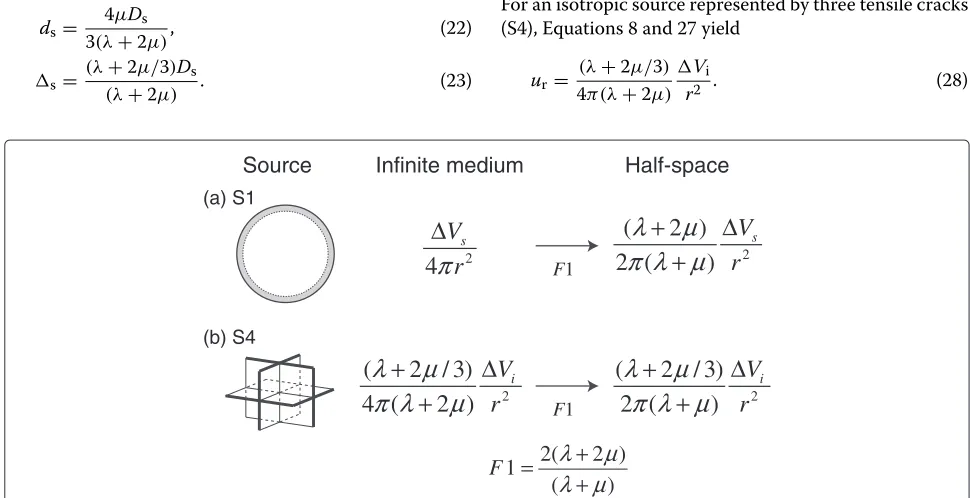
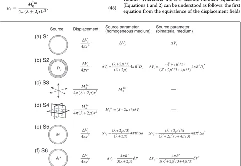
We summarize the radial displacement fields due to the sources examined above in Figure 5. Except for an isotropic source (Figure 5c,d), the displacement fields are given as Vs/(4πr2). Let us first consider the relation-ship between a spherical source (S1, Figure 5a) and an isotropic source represented by three vector dipoles (S3, Figure 5c). The displacement fields of the spherical source and isotropic source are given as
uer= Vs
4πr2, (47)
ur=
M0Iso
4π(λ+2μ)r2, (48)
respectively. The equivalence of these displacements at r>Rprovides the following relation:
Vs=
MIso0
(λ+2μ). (49)
For an isotropic source represented by three tensile cracks (S4), we obtain Equation 8, i.e.,
MIso0 =(λ+2μ/3)Vi. (50)
The relation of Equation 49 is also held between a spherical crack source (S2) and an isotropic source (S3) and between an Eshelby spherical source (S5 and S6) and an isotropic source (S3) (see Figure 5). Then, using Equations 25 and 34, we find that the following relation is held for a spherical crack source (S2) and an Eshelby spherical source with stress-free strain (S5):
MIso0 =(λ+2μ/3)Vf, (51)
whereVf=4πR2a=4πR2Ds. We see from Equations 50 and 51 thatVi=Vf: the sum of three tensile crack volumes is equal to a spherical crack volume or stress-free volume. Therefore, the two seismic moment equations (Equations 1 and 2) can be understood as follows: the first equation from the equivalence of the displacement fields
Source
due to a spherical source (S1) and an isotropic source (S3) (Equation 49) and the second equation from the equiva-lence of three tensile crack volumes and a spherical crack volume or stress-free volume (Equations 50 and 51). The first equation can be used to estimate the actual volume from the seismic moment of an isotropic source (S3).
As shown in Subsection ‘Sources in a bimaterial medium’, no assumption is made on region 1 for a spher-ical source (S1), and its source parameter is given asVs in both homogeneous and bimaterial media (Figure 5a). Thus, we may use Equation 49 with M0Iso in a homoge-neous medium to estimateVs, regardless of the assump-tion on the medium.
It is interesting to note that we may be able to esti-mate a spherical crack volume or stress-free volume (Equation 51) that cannot be observed. This estimation, however, is based on our interpretation of the source pro-cess in region 1. For example, if we consider an Eshelby spherical source with strain-free stress (S6, Figure 5f ), we obtain
MIso0 = 4πR 3
3 δP, (52)
which gives an estimation ofδPin region 1. If we assume a bimaterial medium for a spherical crack source (S2) and consider an Eshelby spherical source with stress-free strain (S5), we have
MIso0 = (λ+2μ)(λ
+2μ/3)
(λ+2μ/3+4μ/3)V
f, (53)
where Vf = 4πR2Ds = 4πR2a. For an Eshelby spherical source with strain-free stress (S6) in a bimaterial medium, we obtain
MIso0 = 4π(λ+2μ)R 3
3(λ+2μ/3+4μ/3)δP
. (54)
These results suggest that the source estimation in region 1 depends on our interpretation, whereas we can uniquely estimate the source parameter of Vs in region 2 from MIso0 .
In volcano seismological studies, waveform inversions have been performed to determine moment tensor solu-tions. If one interprets the isotropic source determined by waveform inversion to be spherical, then Equation 49 can be used to estimate the actual volumeVs. In vol-cano geodetic studies, the Mogi model has been used to interpret volcano deformations. Because the Mogi model is based on a spherical source,Vs is estimated directly. On the other hand, Okada (1992) model uses an isotropic source. Thus, if one estimates the seismic moment of an isotropic source by using Okada’s model, the rela-tion given in Equarela-tion 49 should be used to estimate the
volume change due to the corresponding spherical source or Mogi model.
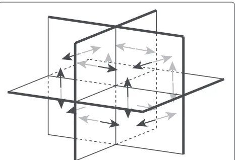
We see that the displacement fields due to the described sources in an infinite medium are all expressed as a func-tion ofr−2(Figure 5). The divergence of such a function is zero, which means that a source volume change must be conserved everywhere in an infinite medium. For all the sources except for an isotropic source, we obtain the following relation in an infinite medium:
4πr2ur=Vs. (55)
The left-hand side represents the volume change of a sphere with an arbitrary radius rcentered at the source, which is equal to Vs. The source volume change in this displacement field is, thus, conserved in an arbitrary subspace enclosing the source. For an isotropic source represented by three tensile cracks (S4), we obtain the following relation:
4πr2ur=
(λ+2μ/3)
(λ+2μ) Vi. (56)
This relation indicates that the source volume change is not conserved. The non-conserved volume may be attributed to compressed volumes in regions close to the cracks (Figure 6). The non-conserved volume is equal to the spherical crack volume or stress-free volume, although the reason why these volumes are equal is not clear. We note that the conservation of a source volume does not hold for displacement fields in a half-space because of the effect of the free surface.
Let us further consider a spherical crack source in a homogeneous medium with the following boundary con-ditions atr=R:
These boundary conditions represent the displacement discontinuitys +ds and the stress or traction discon-tinuity −(P+ P)¯ along the spherical surface. Using Equations 61 and 62, we obtain
uer=
This equation represents the displacement field due to a generalized spherical crack source having both displace-ment and traction discontinuities. Using Equations 59 and 60, we obtain
P¯ = −(3λ+2μ)ds
R. (64)
Substituting Equation 64 into Equation 63, we obtain
uer=
From Equations 57 and 58, we see that Equation 65 becomes Equation 15 for the displacement field due to a spherical source. Therefore, Equation 65 may be regarded as the general form of the equation for the displacement field due to a spherical source represented byPands.
Conclusions
We systematically examined the following seismic sources and their static displacement fields: a spherical source (radiusR) with outward radial expansion (R+s) (S1), a spherical crack source with outward and inward crack wall motions along the spherical surface with displacement discontinuityDs (S2), an isotropic source represented by three mutually perpendicular vector dipoles (S3) or three tensile cracks (S4), and an Eshelby spherical source under-going a transformational expansion (R+a) (S5) or strain-free stress (δP) (S6). Our examinations show that the static radial displacement fields due to these sources except for an isotropic source are given as Vs/(4πr2), where
Vs = 4πR2s is the actual volume. The equivalence of these fields and that due to an isotropic source (S3) gives Vs = MIso0 /(λ + 2μ), where MIso0 is the seis-mic moment of an isotropic source. The actual volume Vs may be uniquely determined from M0Iso in homo-geneous and bimaterial media. We see that the source volume change for an isotropic source defined by three tensile cracks (S4) is equal to the spherical crack vol-ume (4πR2Ds) and stress-free volume (4πR2a). We then obtainMIso0 = (λ+2μ/3)Vf, whereVf is the spheri-cal crack or stress-free volume. This relation depends on our interpretation of the source process. If we consider an Eshelby spherical source with strain-free stress (S6),MIso0 is related toδP. We obtain a different estimation ofVfor δPin a bimaterial medium. This study provides a unified view for quantifying a spherical source using the seismic moment of an isotropic source determined from wave-form inversion analysis in volcano seismological studies.
Competing interests
The authors declare that they have no competing interests.
Authors’ contributions
HK developed the main framework of the study and drafted the manuscript. All authors carried out the theoretical considerations and read and approved the final manuscript.
Acknowledgements
We thank Mare Yamamoto, Minoru Takeo, and Shiro Hirano for their useful discussions. This work was supported by the Japan Science and Technology Agency (JST).
Author details
1Graduate School of Environmental Studies, Nagoya University, Furo-cho,
Chikusa-ku, Nagoya 464-8601, Japan.2Earthquake Research Institute, The
University of Tokyo, 1-1-1 Yayoi, Bunkyo-ku, Tokyo 113-0032, Japan.
Received: 14 December 2013 Accepted: 25 March 2014 Published: 7 April 2014
References
Aki K, Richards PG (2002) Quantitative seismology, 2nd edn. University Science Books, Sausalito
Ampuero JP, FA Dahlen (2005) Ambiguity of the moment tensor. Bull Seism Soc Am 95: 390–400
Backus G, Mulcahy M (1976) Moment tensors and other phenomenological descriptions of seismic sources–I. Continuous displacements. Geophys J R Astr Soc 46: 341–361
Chouet B (1996) A seismic model for the source of long-period events and harmonic tremor. In: Gasparini P, Scarpa R, Aki K (eds) Volcanic seismology. Springer, Berlin, pp 133–156
Chouet B (2013) Introduction to quantitative volcano seismology: fluid-driven sources. In: Fragents SA, Gregg, TKP, Lopes, RMC (eds) Modeling volcanic processes the physics and mathematics of volcanism. Cambridge University Press, Cambridge, pp 331–358
Dreger D, Tkalˇci´c H, Johnston M (2000) Dilational processes accompanying earthquakes in the Long Valley Caldera. Science 288: 122–125 Eshelby JD (1957) The determination of the elastic field of an ellipsoidal
inclusion, and related problems. Proc Roy Soc Ser A 241: 376–396 Fukuyama E, Takeo M (1987) Analysis of the near-field seismogram observed
during the eruption of Izu-Oshima Volcano on November 16. Bull Volcanol Soc Jpn 35: 283–297
Kanamori H, Given J, Lay T (1980) Analysis of seismic body waves excited by the Mount St. Helens eruption of May 18, J Geophys Res 89: 1856–1866 Kawakatsu H, Yamamoto M (2007) Volcano seismology In: Kamanori H (ed)
Treatise on geophysics volume 4—earthquake seismology. Elsevier, Amsterdam, pp 389–420
Kumagai H (2009) Source quantification of volcano seismic signals. In: Mayers RA (ed) Encyclopedia of complexity and systems science. Springer, New York
Kumagai H, Placios P, Ruiz M, Yepes H, Kozono T (2011) Ascending seismic source during an explosive eruption at Tungurahua volcano. Ecuador Geophys Res Lett 38. L01306 doi:10.1029/2010GL045944
Legrand D, Kaneshima S, Kawakatsu H (2000) Moment tensor analysis of near-field broadband waveforms observed at Aso volcano, Japan. J Volcanol Geotherm Res 101: 155–169
Maeda M, Takeo M (2011) Take very-long-period pulses at Asama volcano, central Japan, inferred from dense seismic observations. Geophys J Int 185: 265–282
Mogi K (1958) Relation between the eruptions of various volcanoes and the deformations of the ground surfaces around them. Bull Earthq Res Inst Univ Tokyo 36: 99–134
Müller G (2001) Volume change of seismic. Bull Seism Soc Am 91: 880–884 Nishimura T, Iguchi M (2011) Volcanic earthquakes and tremor in Japan. Kyoto
University Press, Kyoto
Ohminato T, Takeo M, Kumagai H, Yamashina T, Oikawa J, Koyama E, Tsuji H, Urabe T (2006) Vulcanian eruptions with dominant single force components observed during the Asama 2004. volcanic activity in Japan Earth Planets Space 58: 583–593
Okada Y (1992) Internal deformation due to shear and tensile faults in a half-space. Bull Seism Soc Am 82: 1018–1040
Richards PG, Kim WY (2005) Equivalent volume sources for explosions at depth: theory and observations 95: 401–407
Sezawa K (1931) The plastico-elastic deformation of a semi-infinite solid body due to an internal force 9: 398–406
Tameguri T, Iguchi M, Ishihara K (2002) Mechanism of explosive eruptions from moment tensor analyses of explosion earthquakes at Sakurajima volcano, Japan. Bull Volcanol Soc Jpn 47: 197–216
Uhira K, Takeo M (1994) The source of explosive eruptions of Sakurajima volcano, Japan. J Geophys Res 99: 17775–17789
Wielandt E (2003) On the relationship between seismic moment and source volume. http://www.geophys.uni-stuttgart.de/~erhard/skripte/ew/ isomoment/ Accessed May 30 2003
doi:10.1186/1880-5981-66-7
Cite this article as:Kumagaiet al.:Seismic moment and volume change of a spherical source.Earth, Planets and Space201466:7.
Submit your manuscript to a
journal and benefi t from:
7Convenient online submission
7Rigorous peer review
7Immediate publication on acceptance
7Open access: articles freely available online
7High visibility within the fi eld
7Retaining the copyright to your article