Efficient Channel Shortening Equalizer Design
Richard K. Martin
School of Electrical and Computer Engineering, Cornell University, Ithaca, NY 14853, USA Email:[email protected]
Ming Ding
Department of Electrical and Computer Engineering, The University of Texas at Austin, Austin, TX 78712-1084, USA Email:[email protected]
Brian L. Evans
Department of Electrical and Computer Engineering, The University of Texas at Austin, Austin, TX 78712-1084, USA Email:[email protected]
C. Richard Johnson Jr.
School of Electrical and Computer Engineering, Cornell University, Ithaca, NY 14853, USA Email:[email protected]
Received 6 February 2003 and in revised form 9 June 2003
Time-domain equalization is crucial in reducing channel state dimension in maximum likelihood sequence estimation and inter-carrier and intersymbol interference in multiinter-carrier systems. A time-domain equalizer (TEQ) placed in cascade with the channel produces an effective impulse response that is shorter than the channel impulse response. This paper analyzes two TEQ design methods amenable to cost-effective real-time implementation: minimum mean square error (MMSE) and maximum shortening SNR (MSSNR) methods. We reduce the complexity of computing the matrices in the MSSNR and MMSE designs by a factor of 140 and a factor of 16 (respectively) relative to existing approaches, without degrading performance. We prove that an infinite-length MSSNR TEQ with unit norm TEQ constraint is symmetric. A symmetric TEQ halves FIR implementation complexity, enables parallel training of the frequency-domain equalizer and TEQ, reduces TEQ training complexity by a factor of 4, and doubles the length of the TEQ that can be designed using fixed-point arithmetic, with only a small loss in bit rate. Simulations are presented for designs with a symmetric TEQ or target impulse response.
Keywords and phrases:multicarrier modulation, channel shortening, time-domain equalization, efficient computation, symme-try.
1. INTRODUCTION
Channel shortening, a generalization of equalization, has re-cently become necessary in receivers employing multicarrier modulation (MCM) [1]. MCM techniques like orthogonal frequency division multiplexing (OFDM) and discrete mul-titone (DMT) have been deployed in applications such as the wireless LAN standards IEEE 802.11a and HIPERLAN/2, digital audio broadcast (DAB) and digital video broadcast (DVB) in Europe, and asymmetric and very-high-speed dig-ital subscriber loops (ADSL, VDSL). MCM is attractive due to the ease with which it can combat channel dispersion, pro-vided that the channel delay spread is not greater than the length of the cyclic prefix (CP). However, if CP is not long enough, the orthogonality of the subcarriers is lost, causing intercarrier interference (ICI) and intersymbol interference (ISI).
residual ISI to be shaped in the frequency domain. A blind, adaptive algorithm that searches for the TEQ maximizing the SSNR cost function was proposed in [10].
Channel shortening has also applications in MLSE [13] and multiuser detection [14]. For MLSE, for an alphabet of sizeᏭand an effective channel length ofLc+ 1, the complex-ity of MLSE grows as ᏭLc grows. One method of reducing
this enormous complexity is to employ a prefilter to shorten the channel to a manageable length [2,3]. Similarly, in a mul-tiuser system with a flat fading channel for each user, the op-timum detector is the MLSE, yet complexity grows exponen-tially with the number of users. “Channel shortening” can be implemented to suppress a specified number of the scalar channels, effectively reducing the number of users to be de-tected by the MLSE [14]. In this context, “channel shorten-ing” means reducing the number of scalar channels rather than reducing the number of channel taps. In this paper, we focus on channel shortening for ADSL systems, but the same designs can be applied to channel shortening for the MLSE and for multiuser detectors.
This paper examines the MSSNR and MMSE methods of channel shortening. The structure of each solution is ex-ploited to dramatically reduce the complexity of computing the TEQ. Previous work on reducing the complexity of the MSSNR design was presented in [8]. This work exploited the fact that the matrices involved are almost Toeplitz, so the (i+ 1, j+ 1) element can be computed efficiently from the (i, j) element. Our proposed method makes use of this, but focuses rather on determining the matrices and eigenvector for a given delay based on the matrices and eigenvector com-puted for the previous delay.
In addition, we examine exploiting symmetry in the TEQ and in the target impulse response (TIR). In [15], it was shown that the MSSNR TEQ and the MMSE TIR were ap-proximately symmetric. In [16,17], simulations were pre-sented for algorithms that forced the MSSNR TEQ to be perfectly symmetric or skew-symmetric. This paper proves that the infinite-length MSSNR TEQ with a unit norm con-straint on the TEQ is perfectly symmetric. We show how to exploit this symmetry in computing the MMSE TIR, adaptively computing the MSSNR TEQ, and in computing the frequency-domain equalizer (FEQ) in parallel with the TEQ.
The remainder of this paper is organized as follows.
Section 2presents the system model and notation.Section 3
reviews the MSSNR and MMSE designs.Section 4discusses methods of reducing the computation of each design with-out performance loss.Section 5examines symmetry in the impulse response and Section 6 shows how to exploit this symmetry to further reduce the complexity, though with a possible small performance loss.Section 7provides simula-tion results andSection 8concludes the paper.
2. SYSTEM MODEL AND NOTATION
The multicarrier system model is shown inFigure 1and the notation is summarized inTable 1. Each block of bits is di-vided up into N bins and each bin is viewed as a QAM
Table1: Channel shortening notation.
Notation Meaning
x(k) Transmitted signal (IFFT output)
n(k) Channel noise
r(k) Received signal
y(k) Signal after TEQ
N,ν Sizes of FFT and CP
∆ Desired delay (design parameter)
N∆ Number of possible values of∆
h=h0, . . . , hLh
Channel impulse response
w=w0, . . . , wLw
TEQ impulse response
c=c0, . . . , cLc
Effective channel (c=hw)
b=b0, . . . , bν
Target impulse response ˜
Lh=Lh+ 1 Channel length
˜
Lw=Lw+ 1 TEQ length
˜
Lc=Lc+ 1 Length of the effective channel
H L˜cטLwchannel convolution matrix
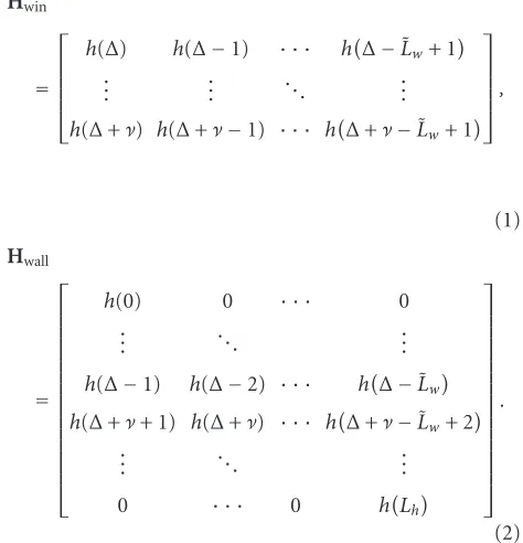
Hwin(∆) Rows∆through∆+νofH
Hwall(∆) Hwith rows∆through∆+νremoved
IN N×Nidentity matrix
[A](i, j) Elementi, jof matrixA
A∗,AT,AH Conjugate, transpose, and Hermitian
signal that will be modulated by a different carrier. An ef-ficient means of implementing the multicarrier modulation in discrete time is to use an inverse fast Fourier transform (IFFT). The IFFT converts each bin (which acts as one of the frequency components) into a time-domain signal. After transmission, the receiver can use an FFT to recover the data within a bit error rate tolerance, provided that equalization has been performed properly.
In order for the subcarriers to be independent, the volution of the signal and the channel must be a circular con-volution. It is actually a linear convolution, so it is made to appear circular by adding a CP to the start of each data block. The CP is obtained by prepending the lastνsamples of each block to the beginning of the block. If the CP is at least as long as the channel, then the output of each subchannel is equal to the input times a scalar complex gain factor. The signals in the bins can then be equalized by a bank of complex gains, referred to as FEQ [18].
The above discussion assumes that CP length +1 is greater than or equal to the channel length. However, mitting the CP wastes time slots that could be used to trans-mit data. Thus, the CP is usually set to a reasonably small value, and a TEQ is employed to shorten the channel to this length. In ADSL and VDSL, the CP length is 1/16 of the block (symbol) length. As discussed in Section 1, TEQ de-sign methods have been well explored [2,3,4,5,6,7,8,9,10,
IFFT
Figure1: Traditional multicarrier system model. (I)FFT: (inverse) fast Fourier transform, P/S: parallel to serial, S/P: serial to parallel, CP: add cyclic prefix, and crossed CP: remove cyclic prefix.
One of the TEQ’s main burdens, in terms of computa-tional complexity, is due to the parameter∆, which is the de-sired delay of the effective channel. The performance of most TEQ designs does not vary smoothly with delay [19], hence a global search over delay is required in order to compute an optimal design. Since the effective channel hasLc+ 1 taps, there areLc+ 1−νlocations in which one can place a win-dow of lengthν+1 of nonzero taps, hence 0≤∆≤Lc−ν. For typical downstream ADSL parameters, this means there are about 500 delay values to examine, and an optimal solution must be computed for each one. One of the goals of this pa-per is to show how to reuse computations from each value of
∆to reduce the computational cost for the following value of
∆, which greatly reduces the overall computational burden.
3. REVIEW OF THE MSSNR AND MMSE DESIGNS
This section reviews the MSSNR and MMSE designs for channel shortening.
3.1. The MSSNR solution
Consider MSSNR TEQ design [5]. This technique attempts to maximize the ratio of the energy in a window of the eff ec-tive channel over the energy in the remainder of the effective channel. Following [5], we define
Hwin the effective channel, andcwall =Hwallw yields the remain-der of the effective channel. The MSSNR design problem can be stated as “minimize cwallsubject to the constraint cwin =1,” as in [5]. This reduces to ever, Ais invertible, butB may not be [20]. An alternative formulation that addresses this is to “maximizecwin sub-ject to the constraintcwall =1,” [20] which works well even whenBis not invertible. The alternative formulation reduces to that satisfies the generalized eigenvector problem
Aw=λ˜Bw, (6)
and the alternative formulation in (5) leads to a related gen-eralized eigenvector problem
Bw=λAw. (7)
The solution for wwill be the generalized eigenvector cor-responding to the smallest (largest) generalized eigenvalue ˜
λ (λ), respectively. Section 4shows how to obtain most of B(∆+ 1) from B(∆), how to obtain A(∆) from B(∆), and how to initialize the eigensolver for w(∆+ 1) based on the solution forw(∆).
3.2. The MMSE solution
The system model for the MMSE solution [3] is shown in
Target impulse response (TIR) impulse responses of the channel, the TEQ, and the target, respec-tively. Here,∆represents transmission delay. The dashed lines indi-cate a virtual path, which is used only for analysis.
The MMSE design uses a TIRbthat must satisfy [2]
is the channel input-output cross-correlation matrix and
Rr=E
is the channel output autocorrelation matrix. Typically,bis computed first, and then (8) is used to determinew. The goal is thathw, the convolution ofhandw, approximates a de-layed version ofb. The TIR is the eigenvector corresponding to the minimum eigenvalue of [3,4,7]
R(∆)=Rx−RxrR−r1Rrx. (11)
Section 4addresses how to determine most ofR(∆+ 1) from R(∆), and how to use the solution forb(∆) to initialize the eigensolver forb(∆+ 1).
4. EFFICIENT COMPUTATION
There is a tremendous amount of redundancy involved in the brute force calculation of the MSSNR design. This has been addressed in [8]. This section discusses methods of reusing even more of the computations to dramatically decrease the required complexity. Specifically, for a given delay∆,
(1) A(∆) can be computed fromB(∆) almost for free, (2) B(∆+ 1) can be computed fromB(∆) almost for free,
(3) a shifted version of the optimal MSSNR TEQw(∆) can be used to initialize the generalized eigenvector solu-tion forw(∆+ 1) to decrease the number of iterations needed for the eigenvector computation,
(4) R(∆+ 1) can be computed fromR(∆) almost for free, (5) a shifted version of the optimal MMSE TIRb(∆) can
be used to initialize the generalized eigenvector solu-tion forb(∆+ 1) to decrease the number of iterations needed for the eigenvector computation.
We now discuss each of these points in turn.
4.1. ComputingA(∆)fromB(∆)
To emphasize the dependence on the delay∆, we write
C=A(∆) +B(∆). (14)
SinceCis symmetric and Toeplitz, it is fully determined by its first row or column:
C(0:Lw,0)=HT
Thus,Ccan be computed using less than ˜L2
h multiply-adds
and its first column can be stored using ˜Lwmemory words. SinceCis independent of∆, we only need to compute it once. Then each time∆is incremented and the newB(∆) is com-puted, A(∆) can be computed fromA(∆) = C−B(∆) us-ing only ˜L2
wadditions and no multiplications. In contrast, the
“brute force” method requires ˜L2
w(Lh−ν) multiply-adds per
The key observation is that
so most ofB(∆+ 1) can be obtained without requiring any computations. Now, partitionB(∆+ 1) as
B(∆+ 1)= α gT
g Bˆ
, (18)
where ˆB is obtained from (17). Since B(∆+ 1) is almost Toeplitz, αand all of the elements ofgsave the last can be efficiently determined from the first column of ˆB[8]. Com-puting each of theseLwelements requires two multiply-adds. Finally, to compute the last element ofg,
gLw =
Hwin
(0:ν,Lw)
T Hwin
(0:ν,0), (19) ν+ 1 multiply-adds are required.
4.3. ComputingR(∆+ 1)fromR(∆)
Recall that for the MMSE design, we must compute
R(∆)=Rx−RxrR−r1Rrx, (20)
where
Rx=ExkxT k
, Rrx=E
rkxTk
,
xk=
x(k−∆), . . . , x(k−∆−ν) T
,
rk=
r(k), . . . , xk−LwT.
(21)
Note thatRxdoes not depend on∆and is Toeplitz. Thus,
Rx(∆+ 1)
(0:ν−1,0:ν−1)=
Rx(∆)
(0:ν−1,0:ν−1)
=Rx(∆)
(1:ν,1:ν).
(22)
LetP(∆)=RxrRr−1Rrx. Observing that
Rrx(∆+ 1)
(0:Lw,0:ν−1)=
Rrx(∆)
(0:Lw,1:ν), (23)
we see that
P(∆+ 1)(0:ν−1,0:ν−1)=P(∆)(1:ν,1:ν). (24)
Combining (22) and (24),
R(∆+ 1)(0:ν−1,0:ν−1)=R(∆)(1:ν,1:ν). (25)
The matrixRr is symmetric and Toeplitz. However, the
in-verse of a Toeplitz matrix is, in general, not Toeplitz [21]. This means thatR(∆) has no further structure that can be easily exploited, so the first row and column of R(∆+ 1) cannot be obtained from the rest ofR(∆+ 1) using the tricks in [8]. Even so, (25) allows us to obtain most of the ele-ments of each R(∆) for free, so onlyν+ 1 elements must be computed rather than (ν+ 1)(ν+ 2)/2 elements. In ADSL,
ν = 32; in VDSL,ν can range up to 512; and in DVB, ν can range up to 2048. Thus, the proposed method reduces
the complexity of calculatingR(∆) by factors of 17, 257, and 1025 (respectively) for these standards.
4.4. Intelligent eigensolver initialization
Letw(∆) be the MSSNR solution for a given delay. If we were to increase the allowable filter length by 1, then it follows that
ˆ
w(∆+ 1)=z−1w(∆)=0,wT(∆)T
(26)
should be a near-optimum solution, since it produces the same value of the shortening SNR as for the previous de-lay. From experience, we suggest that the TEQ coefficients are small near the edges, so the last tap can be removed without drastically affecting the performance. Therefore,
ˆ
w(∆+ 1)=0,wT(∆)(0:L
w−1)
T
(27)
is a fairly good solution for the delay ∆+ 1, so this should be the initialization for the generalized eigenvector solver for the next delay. Similarly, for the MMSE TIR,
ˆ
b(∆+ 1)=0,bT(∆)
(0:ν−1) T
(28)
should be the initialization for the eigenvector solver for the next delay.
4.5. Complexity comparison
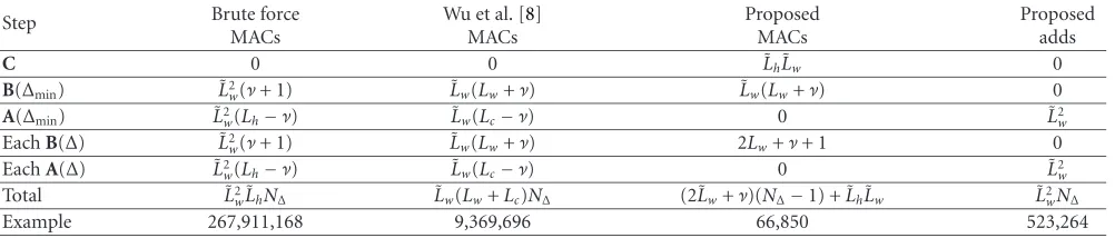
Table 2 shows the (approximate) number of computations for each step of the MSSNR method, using the “brute force” approach, the method in [8], and the proposed approach. Note thatN∆refers to the number of values of the delay that are possible (usually equal to the length of the effective chan-nel minus the CP length). For a typical downstream ADSL system, the parameters are ˜Lw =Lw+ 1=32, ˜Lh=Lh+ 1= 512,Lc =Lw+Lh =542,ν=32, andN∆ =˜Lc−ν=511. The “example” lines inTable 2show the required complex-ity for computing all of theA’s andB’s for these parameters using each approach. Observe that [8] beats the brute force method by a factor of 29, the proposed method beats [8] by a factor of 140, and the proposed method beats the brute force method by a factor of 4008.
Table 3 shows the (approximate) computational re-quirements of the “brute force” approach and the pro-posed approach for computing the matrices R(∆), ∆ ∈ {∆min, . . . ,∆max}. The “example” line shows the required complexity for computing the R(∆) matrices using each method for the same parameter values as the example in
Table 2. The proposed method yields a decrease in complex-ity by a factor of the channel shortener length over two, which in this case is a factor of 16.
Table2: Computational complexity of various MSSNR implementations. MACs are real multiply-and-accumulates and adds are real addi-tions (or subtracaddi-tions).
Step Brute force
MACs
Wu et al. [8] MACs
Proposed MACs
Proposed adds
C 0 0 ˜LhL˜w 0
B(∆min) ˜L2w(ν+ 1) ˜Lw(Lw+ν) L˜w(Lw+ν) 0
A(∆min) L˜2w(Lh−ν) ˜Lw(Lc−ν) 0 ˜L2w
EachB(∆) ˜L2
w(ν+ 1) ˜Lw(Lw+ν) 2Lw+ν+ 1 0
EachA(∆) L˜2
w(Lh−ν) ˜Lw(Lc−ν) 0 ˜L2w
Total ˜L2
w˜LhN∆ L˜w(Lw+Lc)N∆ (2˜Lw+ν)(N∆−1) + ˜LhL˜w ˜L2wN∆
Example 267,911,168 9,369,696 66,850 523,264
Table3: Computational complexity of various MMSE implemen-tations. MACs are real multiply-and-accumulates.
Step Brute force
MACs
Proposed MACs
R(∆min) ˜L3w ˜L3w
EachR(∆) ˜L3
w 2˜L2w
Total N∆˜L3w ˜L2w(2(N∆−1) + ˜Lw)
Example 16,744,448 1,077,248
designs are used, then the computation of the MSSNR ma-trices costsLh/˜Lw times more than the computation of the MMSE matrices, or 16 times more in the example; and if the proposed methods are used, then the computation of the MSSNR matrices costs roughly (2˜Lw+ν)/2˜L2
wtimes as much
as the computation of the MMSE matrices, or 16 timeslessin the example. However, both solutions also require the com-putation of an eigenvector for each delay, and the cost of this step depends heavily on both the type of eigensolver used and the values of the matrices involved, so an explicit comparison cannot be made.
5. SYMMETRY IN THE IMPULSE RESPONSE
This section discusses symmetry in the TEQ impulse re-sponse. It is shown that the MSSNR TEQ with a unit-norm constraint on the TEQ will become symmetric as the TEQ length goes to infinity, and that in the finite length case, the asymptotic result is approached quite rapidly.
5.1. Finite-length symmetry trends
Consider the MSSNR problem of (3), in which the all-zero solution was avoided by using the constraint cwin = 1. However, some MSSNR designs use the alternative constraint w = 1. For example, in [22], an iterative algorithm is proposed which performs a gradient descent ofcwall2. Al-though it is not mentioned in [22], this algorithm needs a constraint to prevent the trivial solution w = 0. A natu-ral constraint is to maintainw =1, which can be imple-mented by renormalizingwafter each iteration. Similarly, a blind, adaptive algorithm was proposed in [10], which is a stochastic gradient descent oncwall2, although it leads to
a window of sizeνinstead ofν+ 1. (In this case,Astill has the same size, but the elements may be slightly different.) For these two algorithms, the solution must satisfy
min
w
wTAwsubject towTw=1. (29)
This leads to a TEQ that must satisfy a traditional eigenvector problem
Aw=λw. (30)
In this case, the solution is the eigenvector corresponding to the smallest eigenvalue. Henceforth, we will refer to the solu-tion of (30) as the MSSNR unit norm TEQ (MSSNR-UNT) solution.
A centrosymmetric matrix has the property that when rotated 180◦(i.e., flip each element over the center of the ma-trix), it is unchanged. If a matrix is symmetric and Toeplitz (constant along each diagonal), then it is also centrosymmet-ric [21]. By inspecting the structure of A, it is easy to see that it is symmetric, and nearly Toeplitz. (In fact, the near-Toeplitz structure is the idea behind the fast algorithms in [8], in which Ai+1, j+1 is computed from Ai, j with a small
tweak.) Hence,Ais approximately a symmetric centrosym-metric matrix. The eigenvectors of such matrices are either symmetric or skew-symmetric, and in special cases the eigen-vector corresponding to the smallest eigenvalue is symmetric [23,24,25]. Thus, we expect the MSSNR-UNT TEQ to be approximately symmetric or skew-symmetric, since it is the eigenvector of the symmetric (nearly) centrosymmetric ma-trixAcorresponding to the smallest eigenvalue. Oddly, it ap-pears that the MSSNR-UNT TEQ is always symmetric as op-posed to skew-symmetric, and the point of symmetry is not necessarily in the center of the impulse response.
To quantify the symmetry of the finite-length MSSNR-UNT TEQ design for various parameter values, we com-puted the TEQ for carrier serving area (CSA) test loops [26] 1 through 8, using TEQ lengths 3 ≤ Lw˜ ≤ 40. For each TEQ, we decomposed w into wsym andwskew, then com-putedwskew2/wsym2. A plot of this ratio (averaged over the eight channels) for the MSSNR-UNT TEQ is shown in
0 50 100 150 200 Length of TEQ
0 0.05 0.1 0.15
wsk
ew
2/
wsy
m
2
Figure3: Energy in the skew-symmetric part of the TEQ over the energy in the symmetric part of the TEQ, forν=32. The data was delay-optimized and averaged over CSA test loops from 1 to 8.
norm of the perturbation was maximized. For example, if the TEQ werew =[1,2,4,2.2], thenwsym =[0,2.1,4,2.1] and
wskew =[1,−0.1,0,0.1]. The value of∆was the delay which maximized the shortening SNR. The point ofFigure 3is not to prove that the infinite-length MSSNR-UNT TEQ is sym-metric (that will be addressed inSection 5.2), but rather to give an idea of how quickly the finite-length design becomes symmetric.
Observe that the MSSNR-UNT TEQ (Figure 3) becomes increasingly symmetric for large TEQ lengths. For parame-ter values that lead to highly symmetric TEQs, the TEQ can be initialized by only computing half of the TEQ coefficients. For MSSNR, MSSNR-UNT, and MMSE solutions, this eff ec-tively reduces the problem from finding an eigenvector (or generalized eigenvector) of an ˆN×Nˆ matrix to finding an eigenvector (or generalized eigenvector) of aN/ˆ 2 × N/ˆ 2 matrix, as shown in [23], where we use ˆNto mean ˜Lwfor the MSSNR TEQ computation and to meanνfor the MMSE TIR computation. This leads to a significant reduction in com-plexity, at the expense of throwing away the skew-symmetric portion of the filter. Reduced complexity algorithms are dis-cussed inSection 6.
5.2. Infinite-length symmetry results
This section examines the limiting behavior ofAandB, and the resulting limiting behavior of the eigenvectors ofA(i.e., the MSSNR-UNT solution). We will show that
lim
Lw→∞
HTH−A F
AF =
0, (31)
where ·F denotes the Frobenius norm [27]. Since HTH
is symmetric and Toeplitz (and thus centrosymmetric), its eigenvectors are symmetric or skew-symmetric. Thus, as
Lw→ ∞, we can expect the eigenvectors ofAto become
sym-metric or skew-symsym-metric. Although this is a heuristic argu-ment, the more rigorous sin(θ) theorem1[28] is difficult to apply.
First, consider a TEQ that is finite, but very long. Specif-ically, we make the following assumptions:
A1: ∆> Lh>ν, A2: Lw>∆+ν.
Such a large∆in A1 is reasonable when the TEQ length is large. Now, we can partitionHas
H=
H1 HL2 HL1 0 0
0 HU3 HM HL3 0
0 0 HU1 HU2 H2
. (32)
The row blocks have heights∆, (ν+ 1), and (Lh+Lw−ν−∆); and the column blocks have widths (∆−Lh), (ν+ 1), (Lh− ν−1), (ν+ 1), and (Lw−ν−∆). The sections [HL2,HL1] and
HL3are both lower triangular and contain the “head” of the channel, [HU1,HU2] andHU3are both upper triangular and contain the “tail” of the channel, H1 andH2 are tall chan-nel convolution matrices, andHM is Toeplitz. ThenHwinis simply the middle row (of blocks) ofH, andHwallis the con-catenation of the top and bottom rows.
Under the two assumptions above, HU3,HM, and HL3 will be constant for all values of∆andLw. As such, the limit-ing behavior ofB=HTwinHwinis
B=0,HU3,HM,HL3,0 T
0,HU3,HM,HL3,0
0,HT3,0T0,HT3,0,
(33)
where H3 is a size (ν+ ˜Lh)×(ν+ 1) channel convolution matrix formed fromJh, the time-reversed channel. SinceB is a zero-padded version ofH3HT3, it has the same Frobenius norm. Also, the values ofLwand∆affect the size of the zero matrices in (33) but notH3(assuming that our assumptions hold), soLw and∆do not affect the Frobenius norm ofB. Therefore,
B2
F=constantBF (34)
whenever our two initial assumptions A1 and A2 are met. The limiting behavior forAis determined by noting that
A=
HT
1H1 · · · 0
HTL2H1 · · · 0
HTL1H1 · · · HTU1H2
0 · · · HTU2H2
0 · · · HT2H2
. (35)
1The sin(θ) theorem is a commonly used bound on the angle between
(Only the top-left and bottom-right blocks are of interest for the proof.) Thus, a lower bound on the Frobenius norm ofA can be found as follows:
A2
F≥HT1H1F2+HT2H22F
≥ h4
2·
∆−Lh+Lw−ν−∆
= h42·
Lw−Lh−ν,
(36)
which goes to infinity as Lw → ∞. In the second inequal-ity, we have dropped all of the terms in the Frobenius norms except for those due to the diagonal elements ofHT1H1and
HT
2H2.
Now, letCHTH, and recall from (14) thatC=A+B.
Thus,
C−A2
F
A2
F
= B2F
A2
F
≤ BF
h4
2·
Lw−Lh+ν, (37)
which goes to zero as Lw → ∞. Thus, in the limit,A ap-proachesC, which is a symmetric centrosymmetric matrix. Heuristically, this suggests that in the limit, the eigenvectors ofA(including the MSSNR-UNT solution) will be symmet-ric or skew-symmetsymmet-ric. However, for special cases (such as tridiagonal matrices), the eigenvector corresponding to the smallest eigenvalue is always symmetric as opposed to skew-symmetric [23]. Every single MSSNR TEQ that we have ob-served for ADSL channels has been nearly symmetric rather than skew-symmetric, suggesting (not proving) that the infi-nite length TEQ will be exactly symmetric. Thus, constrain-ing the finite-length solution to be symmetric is expected to entail no significant performance loss, which is supported by simulation results. Essentially, if v is an eigenvector in the eigenspace of the smallest eigenvalue, thenJv is as well (whereJis the matrix with ones on the cross diagonal and zeros elsewhere) so (1/2)(v+Jv) (which is symmetric) is as well, even if the smallest eigenvalue has multiplicity larger than 1.
Note that in the limit,Bdoes not become centrosymmet-ric (refer to (33)), although it is approximately centrosym-metric about a point offof its center. Thus, we cannot make as strong of a limiting argument for the MSSNR solution as for the MSSNR-UNT solution. Symmetry in the finite-length MSSNR solution is discussed in [15].
6. EXPLOITING SYMMETRY IN TEQ DESIGN
In [15], it was shown that the MMSE target impulse response becomes symmetric as the TEQ length goes to infinity, and inSection 5.2, it was shown that the infinite-length MSSNR-UNT TEQ is an eigenvalue of a symmetric centrosymmetric matrix, and is expected to be symmetric. In [16,17], sim-ulations were presented for forcing the MSSNR TEQ to be perfectly symmetric or skew-symmetric. This section present algorithms for forcing the MMSE TIR to be exactly symmet-ric in the case of a finite length TEQ, and for forcing the MSSNR-UNT TEQ to be symmetric when it is computed in
a blind, adaptive manner via the MERRY algorithm [10]. It is also shown that when the TEQ is symmetric, the TEQ and FEQ designs can be done independently (and thus in paral-lel).
Consider forcing the MSSNR-UNT TEQ to be symmet-ric as a means of reducing the computational complexity. The MSSNR-UNT TEQ arises, for example, in the MERRY algo-rithm [10], which is a blind, adaptive algorithm for comput-ing the TEQ; or in the algorithm in [22] (if the constraint used is a UNT TEQ), which is a trained, iterative algorithm for computing the TEQ. We focus here on extending the MERRY algorithm to the symmetric case. Briefly, the idea behind the MERRY algorithm is that the transmitted sig-nal inherently has redundancy due to the CP, so that redun-dancy should be evident at the receiver if the channel is short enough. The measure of redundancy is the MERRY cost,
JMERRY=E
y(Mk+ν+∆)−y(Mk+ν+N+∆)2,
(38)
whereM =N+νis the symbol length,kis the symbol in-dex, and∆is a user-defined synchronization delay. This cost function measures the similarity between a data sample and its copy in the CP (Nsamples earlier). The MERRY algorithm is a gradient descent of (38).
In practical applications, the TEQ length is even, due to a desired efficient use of memory. Thus, a symmetric TEQ has the formwT =[vT,(Jv)T]. (An even TEQ length is not
necessary; a similar partition can be made in the odd-length case, as will be done for the MMSE target impulse response later in this section.) The TEQ output is
y(Mk+i)=
Lw
j=0
w(j)·r(Mk+i−j), (39)
which can be rewritten for a symmetric TEQ as
y(Mk+i)
= ˜
Lw/2−1
j=0
v(j)·r(Mk+i−j) +rMk+i−Lw+j.
(40)
The Sym-MERRY update is a stochastic gradient descent of (38) with respect to the half-TEQ coefficients v, with a renormalization to avoid the trivial solution v = 0. See
Algorithm 1where
u(i)
=
r(i) +ri−Lw, . . . , r
i−˜Lw 2 + 1
+r
i−˜Lw 2
T .
(41)
For symbolk=0,1,2, . . . ,
compute ˜u. Simulations of Sym-MERRY are presented in
Section 7.
Now, consider exploiting symmetry in the MMSE target impulse response in order to reduce computational complex-ity. Recall that in the MMSE design, first, the TIRbis com-puted as the eigenvector ofR(∆) [as defined in (11)], and then the TEQwis computed from (8). The MSE (which we wish to minimize) is given by
Ee2=bTR(∆)b. (42)
Typically, the CP lengthνis a power of 2, so the TIR length (ν+ 1) is odd. This is the case, for example, in ADSL [29], IEEE 802.11a [30] and HIPERLAN/2 [31] wireless LANs, and DVB [32]. To force a symmetric TIR, partition the TIR as
bT =vT, γ,(Jv)T, (43)
all-zero solution, the nonsymmetric TIR design uses the con-straintb =1. This is equivalent to the constraintvˆ =1. Under this constraint, the TIR that minimizes the MSE must satisfy
ˆ
Rvˆ=λvˆ, (46)
whereλis the smallest eigenvalue of ˆR. Since bothRand ˆR are symmetric, solving (46) requires 1/4 as many compu-tations as solving the initial eigenvector problem. However,
the forced symmetry could, in principle, degrade the perfor-mance of the associated TEQ. Simulations of the Sym-MMSE algorithm are presented inSection 7.
Another advantage of a symmetric TEQ is that it has a linear phase with known slope, allowing the FEQ to be de-signed in parallel with the TEQ. A symmetric TEQ can be classified as either a type I or type II FIR linear phase system [33, pages 298–299]. Thus, for a TEQ withLw+ 1 taps, the transfer function has the form
Wejω=M(ω) exp ofβ. In this case, one must determine the phase response at another frequency, which is more complicated to compute. The response atω=πis fairly easy to compute and will also reveal the value ofβ.
From (47), (48), and (49), given the TEQ length, the phase response of a symmetric TEQ is known up to the fac-torejβ, even before the TEQ is designed. The phases of the
FEQs are then determined entirely by the channel phase re-sponse. Thus, if a channel estimate is available, the two pos-sible FEQ phase responses could be determined in paral-lel with the TEQ design. Similarly, if the TIR is symmet-ric and the TEQ is long enough that the TIR and eff ec-tive channel are almost identical, then the phase response of the effective channel is known, except forβ. If diff eren-tial encoding is used, then the value of βcan arbitrarily be set to either 0 orπ since a rotation of exactly 180 degrees does not affect the output of a differential detector. Further-more, if 2-PAM or 4-QAM signaling is used on a subcarrier, the magnitude of the FEQ does not matter, and the entire FEQ for that tone can be designed without knowledge of the TEQ.
0 500 1000 1500 Symbol index
Adapted Optimal MERRY 10−4
10−3
10−2
10−1
100
MERR
Y
cost
(a)
0 500 1000 1500
Symbol index Adapted
Optimal MERRY Max SSNR 0
0.5 1 1.5 2 2.5 3 3.5
×106
Bi
t
ra
te
(b
p
s)
(b)
Figure4: Performance of Sym-MERRY versus time for CSA loop 4. (a) MERRY cost. (b) Achievable bit rate.
7. SIMULATIONS
This section presents simulations of the Sym-MERRY and MMSE algorithms. The parameters used for the Sym-MERRY algorithm were an FFT of sizeN=512, a CP length ofν=32, a TEQ of length ˜Lw=16 (8 taps get updated, then mirrored), and an SNR ofσ2
xh2/σn2 = 40 dB, with white
noise. The channel was CSA loop 4 (available at [34]). The DSL performance metric is the achievable bit rate for a fixed probability of error
B=
i
log2
1 +SNRi
Γ
, (50)
where SNRi is the signal to interference and noise ratio in
frequency bini. (We assume a 6 dB margin and 4.2 dB cod-ing gain; for more details, refer to [9].)Figure 4shows per-formance versus time as the TEQ adapts. The dashed line represents the solution obtained by a nonadaptive solution to the MERRY cost (38), without imposing symmetry, and the dotted line represents the performance of the MSSNR solution [5]. Observe that Sym-MERRY rapidly obtains a near-optimal performance. The jittering around the asymp-totic portion of the curve is due to the choice of a large step size.
20 40 60 80 100 120
TEQ length Unconstrained
Symmetric TIR 5
5.5 6 6.5 7 7.5 8 8.5 9 9.5 10
Bi
t
ra
te
av
er
age
(M
b
p
s)
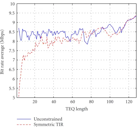
Figure5: Achievable bit rate in Mbps of MMSE (solid) and Sym-MMSE (dashed) designs versus TEQ length, averaged over eight CSA test loops.
Table4: Achievable bit rate (Mbps) for MMSE and Sym-MMSE, using 20-tap TEQs and 33-tap TIRs. The last column is the perfor-mance of the Sym-MMSE method in terms of the percentage of the bit rate of the MMSE method. The channel has an additive white Gaussian noise but no crosstalk.
Loop # MMSE Sym-MMSE Relative
CSA1 8.6323 7.9343 91.91%
CSA2 9.1396 9.1721 100.36%
CSA3 8.5877 8.3360 97.07%
CSA4 8.3157 5.6940 68.47%
CSA5 8.4821 6.3433 74.78%
CSA6 8.8515 9.0016 101.70%
CSA7 7.5244 5.8360 77.56%
CSA8 7.2037 7.4878 103.94%
The simulations for the Sym-MMSE algorithm are shown inFigure 5and inTable 4. InFigure 5, TEQs were de-signed for CSA loops from 1 to 8, then the bit rates were aver-aged. The TEQ lengths that were considered were 3≤Lw˜ ≤ 128. For TEQs with fewer than 20 taps, the bit rate perfor-mance of the symmetric MMSE method is not as good as that of the unconstrained MMSE method. However, asymp-totically, the results of the two methods agree; and for some parameters, the symmetric method achieves a higher bit rate.
the performance (at this filter length) varies significantly de-pending on the channel. Thus, it is suggested that the sym-metric MMSE design should only be used for TEQs with at least 20 taps, and preferably more than that.
8. CONCLUSIONS
The computational complexity of two popular channel shortening algorithms, the MSSNR and MMSE methods, has been addressed. A method was proposed which reduces the complexity of computing the AandB matrices in the MSSNR design by a factor of 140 (for typical ADSL param-eters) compared to the methods of Wu et al. [8], for a total reduction of a factor of 4000 compared to the brute force approach, without degrading performance. A similar tech-nique was proposed to reduce the complexity of comput-ing the R(∆) matrix used in the MMSE design by a fac-tor of 16 (for typical ADSL parameters). It was also shown that the infinite length MSSNR TEQ with a unit norm TEQ constraint has a symmetric impulse response. Algo-rithms for reducing complexity by exploiting symmetry in the TEQ and target impulse response were derived, and sim-ulations were used to show that the symmetric algorithms incur only a minor performance penalty. The Matlab code to reproduce the figures in this paper is available online at
http://bard.ece.cornell.edu/matlab/martin/index.html.
ACKNOWLEDGMENTS
The authors wish to thank Mr. Milos Milosevic of The Uni-versity of Texas at Austin and Mr. Andrew Klein and Mr. John Walsh of Cornell University for their comments. This work was supported in part by Applied Signal Technology (Sunnyvale, CA), the Olin Fellowship from Cornell Univer-sity, and The State of Texas Advanced Technology Program under Project 003658-0614-2001.
REFERENCES
[1] A. N. Akansu, P. Duhamel, X. Lin, and M. de Courville, “Or-thogonal transmultiplexers in communication—A review,”
IEEE Trans. Signal Processing, vol. 46, no. 4, pp. 979–995, 1998.
[2] N. Al-Dhahir and J. M. Cioffi, “Efficiently computed reduced-parameter input-aided MMSE equalizers for ML detection: A unified approach,” IEEE Transactions on Information Theory, vol. 42, no. 3, pp. 903–915, 1996.
[3] D. D. Falconer and F. R. Magee, “Adaptive channel memory truncation for maximum likelihood sequence estimation,”
Bell System Technical Journal, vol. 52, no. 9, pp. 1541–1562, 1973.
[4] N. Al-Dhahir and J. M. Cioffi, “Optimum finite-length equal-ization for multicarrier transceivers,” IEEE Trans. Communi-cations, vol. 44, no. 1, pp. 56–64, 1996.
[5] P. J. W. Melsa, R. C. Younce, and C. E. Rohrs, “Impulse re-sponse shortening for discrete multitone transceivers,” IEEE Trans. Communications, vol. 44, no. 12, pp. 1662–1672, 1996. [6] D. Daly, C. Heneghan, and A. D. Fagan, “A minimum mean-squared error interpretation of residual ISI channel
short-ening for discrete multitone transceivers,” in Proc. IEEE Int. Conf. Acoustics, Speech, Signal Processing (ICASSP ’01), vol. 4, pp. 2065–2068, Salt Lake City, Utah, USA, May 2001. [7] B. Farhang-Boroujeny and M. Ding, “Design methods
for time-domain equalizer in DMT transceivers,” IEEE Trans. Communications, vol. 49, no. 3, pp. 554–562, 2001. [8] J. Wu, G. Arslan, and B. L. Evans, “Efficient matrix
multipli-cation methods to implement a near-optimum channel short-ening method for discrete multitone transceivers,” inProc. 34th IEEE Asilomar Conference on Signals, Systems, and Com-puters (Asilomar ’00), vol. 1, pp. 152–157, Pacific Grove, Calif, USA, October–November 2000.
[9] G. Arslan, B. L. Evans, and S. Kiaei, “Equalization for discrete multitone receivers to maximize bit rate,” IEEE Trans. Signal Processing, vol. 49, no. 12, pp. 3123–3135, 2001.
[10] R. K. Martin, J. Balakrishnan, W. A. Sethares, and C. R. John-son Jr., “A blind, adaptive TEQ for multicarrier systems,”
IEEE Signal Processing Letters, vol. 9, no. 11, pp. 341–343, 2002.
[11] M. Milosevic, L. F. C. Pessoa, B. L. Evans, and R. Baldick, “Optimal time domain equalization design for maximizing data rate of discrete multi-tone systems,” to appear inIEEE Trans. Signal Processing.
[12] K. Vanbleu, G. Ysebaert, G. Cuypers, M. Moonen, and K. Van Acker, “Bitrate maximizing time-domain equalizer design for DMT-based systems,” submitted toIEEE Trans. Communications.
[13] G. D. Forney, “Maximum-likelihood sequence estimation of digital sequences in the presence of intersymbol interference,”
IEEE Transactions on Information Theory, vol. 18, no. 3, pp. 363–378, 1972.
[14] I. Medvedev and V. Tarokh, “A channel-shortening multiuser detector for DS-CDMA systems,” inProc. 53rd Vehicular Tech-nology Conference (VTC ’01), vol. 3, pp. 1834–1838, Rhodes, Greece, May 2001.
[15] R. K. Martin, M. Ding, B. L. Evans, and C. R. Johnson Jr., “In-finite length results and design implications for time-domain equalizers,” to appear inIEEE Trans. Signal Processing. [16] C. Ribeiro, V. Silva, and P. S. R. Diniz, “Impulse response
shortening for xDSL discrete multitone modems with linear phase filters,” inII Conferencia Internacional de Telecomuni-caciones y Electr´onica (TELEC ’02), Santiago de Cuba, Cuba, July 2002.
[17] C. Ribeiro, V. Silva, and P. S. R. Diniz, “Linear phase impulse response shortening for xDSL DMT modems,” inProc. IEEE International Telecommunications Symposium (ITS ’02), Natal, Brazil, September 2002.
[18] J. M. Cioffi, “A multicarrier primer,” ANSI TIE1.4 Commit-tee Contribution, No. 91-157, November 1991,http://www. stanford.edu/∼cioffi/.
[19] K. Van Acker, G. Leus, M. Moonen, O. van de Wiel, and T. Pollet, “Per tone equalization for DMT-based systems,”
IEEE Trans. Communications, vol. 49, no. 1, pp. 109–119, 2001.
[20] C. Yin and G. Yue, “Optimal impulse response shortening for discrete multitone transceivers,”Electronics Letters, vol. 34, no. 1, pp. 35–36, 1998.
[21] M. H. Hayes,Statistical Digital Signal Processing and Modeling, John Wiley & Sons, New York, NY, USA, 1996.
[22] M. Nafie and A. Gatherer, “Time-domain equalizer training for ADSL,” inProc. IEEE International Conference on Commu-nications (ICC ’97), vol. 2, pp. 1085–1089, Montreal, Quebec, Canada, June 1997.
[24] A. Cantoni and P. Butler, “Properties of the eigenvectors of persymmetric matrices with applications to communication theory,”IEEE Trans. Communications, vol. 24, no. 8, pp. 804– 809, 1976.
[25] J. Makhoul, “On the eigenvectors of symmetric Toeplitz ma-trices,” IEEE Trans. Acoustics, Speech, and Signal Processing, vol. 29, no. 4, pp. 868–872, 1981.
[26] K. Sistanizadeh, “Loss characteristics of the proposed canon-ical ADSL loops with 100-Ohm termination at 70, 90, and 120 F,” ANSI T1E1.4 Committee Contribution, No. 161, November, 1991.
[27] G. H. Golub and C. F. Van Loan,Matrix Computations, Johns Hopkins University Press, Baltimore, Md, USA, 3rd edition, 1996.
[28] C. Davis and W. Kahan, “The rotation of eigenvectors by a perturbation. III,” SIAM Journal on Numerical Analysis, vol. 7, no. 1, pp. 1–46, 1970.
[29] T. Starr, J. M. Cioffi, and P. T. Silverman,Understanding Digi-tal Subscriber Line Technology, Prentice-Hall PTR, Upper Sad-dle River, NJ, USA, 1999.
[30] The Institute of Electrical and Electronics Engineers, “Wire-less LAN Medium Access Control (MAC) and Physical Layer (PHY) Specifications,” IEEE Standard 802.11a, 1999. [31] The European Telecommunication Standards Institute,
“Broadband Radio Access Networks (BRAN); High Perfor-mance Radio Local Area Networks (HIPERLAN) Type 2; System Overview,” ETR101 683 114, 1999.
[32] The European Telecommunication Standards Institute, “Dig-ital Video Broadcasting (DVB); Framing Structure, Channel Coding and Modulation for Digital Terrestrial Television,” ETSI EN 300 744 V1.4.1, 2001.
[33] A. V. Oppenheim and R. W. Schafer,Discrete-Time Signal Pro-cessing, Prentice-Hall, Upper Saddle River, NJ, USA, 2nd edi-tion, 1998.
[34] G. Arslan, M. Ding, B. Lu, M. Milosevic, Z. Shen, and B. L. Evans, The University of Texas at Austin. Matlab DMT-TEQ toolbox version 3.1,http://www.ece.utexas.edu/∼bevans/ projects/adsl/dmtteq/dmtteq.html.
Richard K. Martinobtained dual B.S. de-grees in physics and electrical engineering from the University of Maryland, College Park in 1999 (Summa Cum Laude) and an M.S. in electrical engineering from Cornell University in 2001. He is pursuing his Ph.D. in electrical engineering in Cornell Univer-sity. His research interests include equaliza-tion for multicarrier systems; blind, adap-tive algorithms; reduced complexity
equal-izer design; and exploiting sparsity for performance improvement of adaptive filters. He has had five journal papers and twelve con-ference papers accepted for publication. He is a lead author of the bookTheory and Design of Adaptive Filters Answer Book, and he has three pending patents.
Ming Dingreceived his B.S. degree from the Department of Electronic Science at Nankai University in 1995 and his M.E. degree from the Department of Electrical and Computer Engineering at National University of Sin-gapore in 1999, respectively. From 1995 to 1997, Ming had been an R&D Engineer with the National Post and Telecommunications Industry Corporation (PTIC), Shanghai.
From April 1999 to August 2000, he has been working as an R&D
Engineer for the Centre for Wireless Communications at the Na-tional University of Singapore. Ming is currently a full-time Ph.D. student in electrical engineering at the University of Texas at Austin. Since 2001, he has been a Research Assistant with Em-bedded Signal Processing Laboratory at The University of Texas at Austin. During summers, he serves among the co-op student staff at DSPS R&D Center, Texas Instruments, Dallas. During Fall 2002, he was a nondegree graduate student at Cornell University. His current research interests include multicarrier modulation, channel equalization, and adaptive filtering with applications in broadband wireless and wireline communications.
Brian L. Evansreceived his BSEECS degree from the Rose-Hulman Institute of Tech-nology in May 1987, and his MSEE and Ph.D.EE degrees from Georgia Institute of Technology in December 1988 and Septem-ber 1993, respectively. From 1993 to 1996, he was a Postdoctoral Researcher in design automation for embedded systems in the Department of EECS, University of Califor-nia, Berkeley. From 1996 to 2000, he was an
Assistant Professor in the Department of Electrical and Computer Engineering (ECE) at The University of Texas at Austin. Since 2000, he has been an Associate Professor of ECE at UT Austin. In Fall 2002, he spent a revitalizing sabbatical at Cornell University with Professor Rick Johnson’s research group. His research interests in-clude the design and embedded real-time software implementa-tion of high data rate equalizers for ADSL/VDSL transceivers, high-quality halftoning for desktop printers, smart image acquisition for digital still cameras, and high-resolution 3D sonar imaging sys-tems. Professor Evans has published over 100 refereed conference and journal papers. Professor Evans is a member of the Design and Implementation of Signal Processing Systems Technical Committee of the IEEE Signal Processing Society, and a recipient of the 1997 US National Science Foundation CAREER Award.
C. Richard Johnson Jr. was born in Ma-con, GA in 1950. He is currently a Pro-fessor of electrical and computer engineer-ing at Cornell University, Ithaca, NY. Pro-fessor Johnson received the Ph.D. degree in electrical engineering with minors in engineering-economic systems and art his-tory from Stanford University in 1977. In 1989, he was elected a Fellow of the IEEE “for contributions to adaptive parameter