---- ---- ----
-
- -
-
--
-
-
-Publication Number GA26-1672-0
IBM Disk Storage
Management Guide
Error Handling
Cross-System
File Number
Any reference to an IBM program product in this docu-ment is not intended to state or imply that only IBM's program product may be used. Any functionally equiva-lent progra.m may be used'instead.
Flnt Edition (December 1982)
This is the first edition of the IBM Disk Storage Management Guide, Publication No. GBOF 1205, Error Handling, Publication No. GA26-1672.
Information in this publication is subject to change. Before using this publication in connection with the use of IBM equipment, contact the local IBM branch office for revisions.
It is possible that this material may contain reference to, or information about, IBM products (machines and programs), programming, or services that are not announced in your country. Such references or information must not be construed to mean that IBM intends to announce such IBM products, programming, or services in your country.
Copies of this and other IBM publications can be obtained through IBM branch offices. A form for reader's comments is provided at the back of this publication. If the form has been removed, send your comments to the address below.
This manual was prepared by the IBM General Prodllcts Division, Tech~ical Publishing, Department G26/HI5, 555 Bailey Ave., San J~, California, 95150.
Preface
The
IBM Disk Storage Management Guide
provides tutorial information and guidance to help you with the physical management of your disk storage. The informa-tion is intended for IBM disk storage customers. It is written especially for operations personnel, including operators and system programmers, and others who may have responsibility for disk storage management tasks.The material is in separate manuals, organized as a set. Each manual has a separate order number, but the manuals as a set have a common Bill of Form Publica-tion Number, GBOF 1205. Manuals in the
IBM Disk
Storage Management Guide
are:Background Reference Information
GA26-1675Error Handling
GA26-1672The material in the Guide applies to the following products.
Disk Storage: 3330, 3340, 3344,3350,3370, 3375, 3380
Storage Control: 3830-2, ISC, IFA, DDA, FTA, 3880-1, 2, 3, 11, 13
Operating Systems: OS jMVS, OS jVS I. Error records generated under the control of DOSjVSE and VMj370 can be processed by the System Exception reports installed under OSjVSI and OSjMVS.
IBM Disk Storage Management Guide, Error
Handling
This
Error Handling
manual discusses data and equip-ment errors that can occur in disk storage operations. The focus is on data errors because the Device SupportFacilities program enables you to handle this type of error directly. New reports produced by the Environmental Recording, Editing, and Printing (EREP) program are described. These reports help you decide when and how to use the Device Support Facilities program.
Prerequisite
You should be familiar with error definitions given in the
Disk Storage Management
manual,Background
Refer-ence Information,
Publication Number GA26-1675. Refer to the section, "Error Description."Terminology
The term
recovery
is used to encompass several functions:• Recovery from an error - meaning to overcome an error by automatic correction or retry and thus allow the operation that was in progress to
be
continued. These error recovery procedures are performed by the subsystem and system, as described inBackground
Reference Information,
Publication No. GA26-1675.• Recovery from the cause of an error at the source, which is the subject of this
Error Handling
manual.• Recovery of data, meaning to restore and reconstruct data from another source.
A
hardware service representative
is called acustomer
engineer
in IBM.Programs
Information in the
Error Handling
manual refers to:• Environmental Recording, Editing, and Printing (EREP) program release 1.3 with the System Excep-tion reports feature.
• Device Support Facilities release 6 and above.
Bibliography
IBM
4341Processor Functional
GA24-3672Characteristics and Processor
Order
Complex Configura tor
Terminology Number
IBM Vocabulary for Data Processing
GC20-I699 ProgramsTelecommunications, and Office
Data Facility Data Set Services:
SC26-3949Systems
User's Guide and Reference
describes dump and restore functions
Disk Storage for system and standalone users.
Reference Manualfor IBM 3330
GA26-I6I5Device Support Facilities
GC35-0033Series Disk Storage
describes the commands to initializeReference Manualfor IBM
GA26-I6I9 and maintain disk storage volumes3340/3344 Disk Storage
for system and standalone users.Reference Manualfor IBM 3350
GA26-I638DOS/VSE Messages
GC33-5379Direct Access Storage
lists and interprets themessages that the system
IBM 3370 Direct Access
GA26-I657 issues for DOS users.Storage Description
DOS/VSE System Utilities
GC33-5381IBM
3375Direct Access Storage
GA26-I666 describes the utility programsDescription and User's Guide
for DOS users.IBM 3380 Direct Access Storage
GA26-I664Environmental Recording, Editing,
GC28-0772Description and User's Guide
and Printing (EREP) Program
describes the functions of this
Storage Control program, and the keyword parameters
IBM 3830-2 Storage Control
GA26-I617 and control statements for the systemgives detailed descriptions of programmer. The manual includes
channel commands, and status and instructions on preparing the DASDID
sense information. and LIMIT control statements used
IBM Integrated Storage Control
GA26-I620 for the System Exception reports.gives detailed descriptions of
OS/VS Message Library:
GC38-IOOIchannel commands, and status and
VS1 System Messages
sense information.
OS/VS1 Utilities Manual
GC26-3901IBM 3880 Storage Control
describes the capabilities ofDescription
gives detailed descriptions the OS/VSI utility programs of channel commands, and status and and the control statementssense information. used with each for OS /VS 1 users.
For 3880 Models 1, 2, and 3 GA26-I66I
OS/VS2 Message Library:
GC38-IOO2For 3880 Model 11 GA32-0060
VS2 System Messages
For 3880 Model 13 GA32-0062 describes the messages
IBM Systems/370 Model 115
GA33-I5IO issued on the system operatorFunctional Characteristics
for consoles for OS /VS2 users.direct disk attachment (DDA).
OS/VS2 MVS Utilities
GC26-3902IBM System/370 Model 125
GA33-I506 describes how to use OS/VSFunctional Characteristics
for utilities under OS/VS2 MVS.direct disk attachment (DDA). It includes information on
IBM System/370 Model 135
GA33-3005 IEHMOVE, IEBGENER, IEBCOPY,Functional Characteristics
for and IEHLIST for MVS users.integrated file adapter (IF A).
VM/370 System Messages
GC20-1808Table of Contents
Introduction. . . . 1 Guidelines for Recovery Action ... 21
Error Information ... 1 Error Handling During Normal Traditional Types of Information ... 1 Production ... 21
New Types of Information- Steps in Error Handling ... 23
System Exception Reports ... 2 Considerations for Permanent and Temporary Probable Failing Unit ... 3 Errors ... 28
Resources for Recovery from Errors ... 4 Use of Device Support Facilities ... 29
Hardware - Service Representative ... 4 Security Functions ... 29
Volume - Device Support Facilities ... 4 Check Number Specification ... 29
Description of Resources ... 5
System Exception Reports Description ... 5
System Error Summary (Part 2) ... ! • • • • • • • • 5
Subsystem Exception, DASD ... 5
DASD Data Transfer Summary ... 6
System Exception Reports, Comparison Summary ... 7
Device Support Facilities Description ... 8
Error Handling Functions ... 8
Surface Checking ... 8
Bypassing Defects ... 9
Results When Surface Checking ... 29
Data Protection ... 30
Commands and Parameters for Error Handling ... 30
If-
Then-Else Statement Sequence ... 30Failure to Execute Command ... 31
Use of Other Manuals ... 31
When to Use EREP Manual ... 31
When to Use Device Support Facilities Manual ... 31
Where to Find Data Copy Information ... 31
Rewriting Home Address and Specific Guidelines for Device Types ... 32
Record Zero ... 10 Error Handling for 3330 ... 34
Hardware and Data Verification Tests ... 10 Error Handling for 3340 ... 36
Device Support Facilities Error Handling Error Handling for 3344 ... 38
Functions, Comparison Summary ... 11 Error Handling for 3350 ... 40
How to Read the EREP System Exception Reports ... 12
Error Handling for 3370 ... 44
Error Handling for 3375 and 3380 ... 47
How to Read the Title Line ... 13 Impact of Error on Data ... 52
How to Read the System Error Summary When the Source is the Hardware ... 52
(Part 2) ... 14 Validity of Data ... 52
How to Read the Subsystem Exception, Accessibility of Data ... 52
DASD ... 16 When the Source is a Volume ... 53
How to Read the DASD Data Transfer Summary ... 18
How to Quickly Find Volume Information ... 20
Glossary ... 55
Index ... 56
Introduction
Error Information
Traditional Types of Information
Reliable and effective performance of your data processing system depends on recognizing and handling errors that may occur in disk storage operations. Techniques are built into the subsystem and system to detect error conditions, and recover from most errors automatically. However, some errors cannot
be
corrected internally, and others, even though corrected at the time, continue to recur because the cause of the error persists. When this happens, you can evaluate the error situation in relation to your installation, and take appropriate action.Information and program functions are now provided to allow you to deal directly with disk storage errors. You use these resources to interpret an error situation, and in some cases, remedy the cause of the error to prevent its recurrence. You will benefit by:
• Averting the need to call for outside service for problems that previously required such service
• Maintaining control of your stored data
• Reducing the time spent in problem determination
• Improving the perfo~mance of your system
First you need information that an error has, in fact, occurred. Then, sufficient details about the error must be obtained to evaluate whether action should
be
taken, where it should be applied, and the means to be used to recover from the cause of the error.There are different ways of obtaining error information.
• Messages are displayed at a terminal or console to give immediate notification of an error.
• Lists of error messages may be printed or displayed later to allow review of events that occurred during a given time period.
• Reports based on analysis of error information may be produced to diagnose an error situation.
Traditional types of error information may not provide the information in a form you need to evaluate an error situation.
System console messages give immediate notification of an error. However, the content of the messages and the conditions that cause them to be issued varies depending on the component or program in control. Most error messages contain information on the type alld location of errors and give sense information in hexadecimal code. But the information may not receive attention because it is displayed for such a short time, and messages of disk storage equipment and data checks are not highlighted nor do they require operator action.
Messages displayed at a system console may
be
stored for later examination. When a system log is printed, all of the messages that were displayed are listed. When a job log is printed, messages applying to the particular job are listed. In both cases, messages on disk storage errors mustbe
extracted from many other messages.Besides system messages, most programs have procedures for notifying the user of
errors, and the user may alert operations personnel that an error has occurred.
The Environmental Recording, Editing, and Printing (EREP) program produces
reports based on the contents of a system's error log. Traditionally these reports have
been used mostly by service representatives.
New Types of Information - System Exception Reports
To improve the usefulness of error reporting, the EREP program now produces a set
of new reports to help you determine the nature of error incidents and make decisions
regarding possible recovery actions. These are called System Exception reports.
The System Exception reports describe the type and location of errors and give other
needed details. The reports for disk storage:
•
Cover all the systems that share the disk storage. The log records of each system
are used as a basis for a multisystem report.
•
Cover temporary as well as permanent errors. (Temporary errors are those where
the data is corrected or the operation is successfully retried automatically.)
•
Determine the probable source of the error.
The source of an error is a more reliable basis for recovery than the type of error
because a type of error may have different sources. For instance, a data check type
of error may be caused by a problem in the controller hardware or by a defect on the
disk surface. The source of an error points to where recovery action should
be
applied and the means to use for recovery.
Probable Failing Unit
The probable source of an error as defined by the EREP program is referred to as a
probable failing unit in the System Exception reports.
The categories of probable failing units for disk storage are as follows:
Channel
Refers to a channel of a processor.
Storage control
Controller
Device
Volume
Refers to a 3830, ISC, IF A, DDA, FTA, or 3880.
Ifit is a 3880,
it refers to a storage director.
Refers to the controller of a string of disk storage, usually housed
in the A unit of the string.
Refers to the drive and access mechanism physical components.
Refers to the disks associated with a volume serial number; that
is, the disks that can be accessed with a given I/O address.
If
the probable failing unit is the channel, storage control, controller, or device, the
source of the error is defined as the hardware. The error may be detected during a
write, read, or control operation.
If
the probable failing unit is defined as a volume, the source of the error is the disk
media or something associated with writing or reading data at the media. The exact
cause of an error on a volume may be a defect on the disk surface, a change in
alignment of the access mechanism, or some unknown contributor such as an
electrical interference or temperature deviation during a write or read operation.
The error is detected during a read operation and is always a data type error.
Resources for Recovery from Errors
The means used for recovery from an error depends on the source of the error.
Hardware - Service Representative
When the source of an error is a probable failing unit of hardware, a hardware
service representative (customer engineer) performs the recovery action. The service
representative uses EREP reports and other tools to further isolate the cause of the
error.
When the cause of the problem is established, it is usually possible to replace the
failing component, which may
be
a logic card, power component, or other such field
replaceable unit (FRU).
Volume - Device Support Facilities
When the source of an error is a probable failing unit of a volume, you use the Device
Support Facilities program for recovery. You control recovery actions by using
Device Support Facilities commands to perform the functions needed.
A frequent cause of a data type error is a defect on the disk surface. (The term
defect applies to anything that interferes with the precise magnetic recording on the
surface.) Although the probability is low that such a defect will result in a permanent
data error, when it does occur, there are potentially serious consequences in terms of
loss of data. You can use Device Support Facilities to treat a problem that is causing
a permanent data error or excessive temporary errors.
For error handling, Device Support Facilities checks the surface of the disks and, if
defects are confirmed, automatically makes provisions to bypass the defective area.
In addition to checking and bypassing defects in user records, Device Support
Facilities has extensive means for reconstructing a home address when data errors
occur in this area and then for rewriting home addresses and record zeros.
Checking and bypassing functions are used after it has been determined that the
source of a data error is the volume (or media) and not the hardware. This
Description of Resources
This section describes the System Exception reports printed by the EREP program
and the error handling functions provided by the Device Support Facilities program.
Later, guidelines will be given on how to use information from the System Exception
reports to perform Device Support Facilities functions.
System Exception Reports Description
System Error Summary (Part 2)
Subsystem Exception, DASD
The EREP program prints a full set of System Exception reports in a single job step;
however, you need only three of these reports for information on disk storage errors.
The other System Exception reports apply to other components or are intended
primarily for service representatives.
The three System Exception reports you will use for disk storage error handling are:
•
System Error Summary (Part 2)
•
Subsystem Exception, DASD
•
DASD Data Transfer Summary
Later, each report will be illustrated along with instructions on how to read it.
The System Error Summary (Part 2) report applies to disk storage and tape storage.
The report lists
each incident of a permanent I/O error. The type of error may be a
data check or an equipment check. The errors are in sequence according to the time
they occurred. Each error incident has the
job name of the job in progress. A
probable failing unit is given for each of the errors.
This report is helpful if there is a problem while running a particular job and you
want to determine if any type of I/O error occurred at the time. The report also is
helpful in giving a quick perspective of all permanent I/O errors during the time
covered by the report.
The Subsystem Exception, DASD, report applies only to
disk storage. The report
lists
accumulated permanent and temporary errors. The accumulated errors are
given for each unit in the probable failing unit category. For example, each volume
with errors is listed in the volume category. The accumulated total will include each
permanent error listed in the System Error Summary (Part 2). Description of the
type of error depends on the probable failing unit.
• If
the probable failing unit is a
hardware component, permanent and temporary
errors can be a
data, control, or equipment type of error.
• If
the probable failing unit is a
volume, both permanent and temporary errors are
always a data type of error.
DASD Data Transfer Summary
The hardware probable failing units are listed first and the volume probable failing
units are listed last.
Usage, in terms of number of thousands seeks and number of megabytes read, is
given for each unit reporting errors. This information can be used along with the
total number of errors for the unit to assist in evaluating whether recovery action
should be taken.
The DASD exception report will bring to your attention any problems related to disk
storage operation that may need further investigation and treatment.
Ifthe span of
error records in the report covers more than three days, a message is printed at the
top of the report. A report that spans longer
than~hreedays may not provide the
most accurate probable failing unit indication because corrective action may have
been taken.
To improve the report's usefulness, you can establish limits for the number of
temporary data errors acceptable in your installation. Probable failing units with
temporary data errors below this limit will not be printed. Limits can be set for each
type of error and for each storage control type and disk storage type. (Limits should
not be set for 3375 and 3380s because temporary data errors have a threshold
established in the subsystem.) Limit control statements are used to make these
specifications.
Ifthere are units that have errors that are not reported because the
errors did not exceed the limit, a message gives the total number of such units.
The DASD Data Transfer Summary report also applies to disk storage but only to
data check type errors. It
gives details of data errors. All volumes that were listed in
the DASD exception report (where they are listed with a total count of errors) are
given in this report with details of the data errors for that volume.
Detailed information is provided for all permanent data errors, because permanent
errors are logged in the system error log. For temporary errors, the information is
provided
if
the error description (not just the count) is logged in the system error log.
Whether a temporary error is logged depends on the disk storage product type and
the area in which the error occurs. Logging is described in the manual, Background
Reference In/ormation, Publications No. GA26-1675.
The DASD Data Transfer Summary has two sections, one for Volume probable
failing units and one for Other probable failing units. The same type of information
about the data errors is provided in both sections, but the means for recovery action is
different.
For data errors in the Volume section, you can use Device Support Facilities for
recovery action.
System Exception Reports, Comparison Summary
System Error Summary Subsystem Exception, DASD DASD Data Transfer Summary
Tape and disk storage devices DASD devices DASD devices
Permanent errors: equipment and data Permanent and temporary errors: Permanent and temporary checks equipment and data checks errors: data checks Each incident Accumulated totals Details by volume
Probable failing unit: hardware and vol- Probable failing unit: hardware and vol- Probable failing unit: volume and
ume ume other
N umber of thousands of seeks N umber of megabytes read
Device Support Facilities Description
Error Handling Functions
Surface Checking
The Device Support Facilities program has functions for initialization and
maintenance of disk storage volumes. Commands for error handling appear in both categories.
The Device Support Facilities program provides for checking disk surfaces to determine if there are defects on the media. (Data cannot consistently be written correctly on a defective area, and this results in detection of errors when the data is read.)
If
there are defects on the surface, the program arranges to bypass them, so that no new data is written in the defective area. These surface checking functions are specified with parameters of the INSPECT and INIT commands.Surface checking is done by writing and reading sets of special bit patterns. The checks range in complexity from primary tests to advanced tests. The advanced tests require more time and, in general, provide more reliable surface inspection.
Writing special bit patterns on the track for surface checking destroys any data already on the track. Before the write and read tests are started, user data can sometimes be saved by the Device Support Facilities program or it can be moved to a backup device by using a dump or copy program.
Checking can be done on individual tracks or blocks, or on all of the tracks or blocks ofa volume. .
The determination as to whether there is a defect is based on the repeatability of errors.
If
errors recur in the same area, that area of the track is determined to be defective.The INSPECT command of Device Support Facilities provides for surface checking of specific tracks or blocks suspected of having a problem. When checking specific tracks or blocks, the advanced tests for the particular disk storage type are used where applicable. The Preserve parameter causes existing data to be saved, if it can be read.
All tracks or blocks can be checked with the IN IT command. Checking all of a volume is first done with a set of primary patterns that accomplish a high-level sifting to expose possible errors. The suspected errors are then subjected to an advanced, and more time-consuming, set of patterns where applicable. With the INIT command, Device Support Facilities does not preserve data; therefore, you must use another program to copy the entire volume to another device before using the INIT command or the data will be destroyed. Use of the IN IT command is not limited to the installation process.
Bypassing Defects
If
surface defects are confirmed by surface checking with the advanced tests, the
defects are bypassed automatically.
Bypassing Defects on Count, Key, and Data Dellces
When defects are confirmed, the defective area on a track is skipped and another
location on the same track is used. A certain number of defective areas on a track
can be skipped. Space at other locations on the track is already reserved so it does
not subtract from that available for user records when making space calculations.
If
this reserved space is exhausted, the entire track is surface-checked again.
If
too
many defects remain, the track is flagged as defective and an alternate track is
assigned. This technique of skip displacement applies for the 3340, 3344, 3350,
3375, and 3380. The number of skips that can be made per track differs for device
types:
3340 and 3344
3350
3375 and 3380
1 skip
3 skips
7 skips
With the 3330, defective areas on a track cannot be skipped. Instead, an alternate
track is assigned if there are defects on the track. This applies only for permanent
data errors.
All disk storage types reserve certain tracks for assignment as alternates.
In addition to the program automatically bypassing defects, the user can specify that
alternate tracks are to be unconditionally assigned to specific tracks. With this
function, Device Support Facilities does not perform checking functions.
When defective areas on a track are skipped or an alternate track is assigned to
replace a defective primary track, the Device SuppOrt Facilities program handles all
of the associated record keeping. When defective areas are skipped, the skip
displacement information is recorded in the home address area of the track.
If
an
alternate track is assigned, the defective track is flagged in the home address area,
and record 0 is rewritten. (Record 0 carries the alternate and primary track
associations: RO of the defective primary track contains the address of the alternate
track, and RO of the alternate track contains the address of the defective primary
track.)
When specific tracks or all tracks are checked, the home address and record zero are
always rewritten.
If tracks previously flagged as defective are found to be usable while surface
checking with the INSPECT or INIT command, they are reclaimed for use if the
Reclaim option is specified.
Bypassing Defects on Fixed-Block Architecture Devices
With fixed-block architecture devices, defective blocks are flagged defective and an
alternate block is assigned. The alternate block is usually on the same cylinder if a
block is available.
The user can specify that alternate blocks are to be unconditionally assigried for
specific blocks. With this function, Device Support Facilities does not perform
surface checking.
When alternate blocks are assigned, Device Support Facilities handles all of the
associated record keeping. The alternate block information is recorded in the ID
area that precedes the data area.
If
blocks previously flagged as defective are found to be usable while surface
checking with the INIT command, the blocks are reclaimed for use with the Reclaim
option of the INIT command.
Rewriting Home Address and Record Zero
After checking the surface of specific tracks or all tracks, Device Support Facilities
rewrites the home address and record zero on count, key, and data devices.
If
the
program detects data errors in the home address or record zero while performing
surface checking, it handles the problem automatically.
Besides Device Support Facilities detection of home address errors while surface
checking, data errors in the home addresses may be recognized from sense
information in error reports. In this case, functions are available for you to
deliberately rewrite home addresses and record zeros.
If
data checks occur in the home address of more than one track, there may also be a
potential problem reading home addresses of other tracks. The problem usually can
be handled by rewriting the home addresses of all the tracks on the volume with the
Device Support Facilities INIT command with the Validate parameter. The
addresses are rewritten without checking the surface for possible defects.
Device Support Facilities attempts to reconstruct and rewrite the home address in the
original location on the track.
If
it is not possible to rewrite the home address in the
same location, attempts are made to move it to a different location on the track on
3340,3344, 3350, 3375, and 3380 devices. This relocation does not subtract from the
available track capacity.
Hardware and Data Verification Tests
Functions provided with the ANALYZE command help distinguish whether a data
error was caused by a hardware problem. These functions are for device types that
have non-removable head and disk assemblies. Hardware tests exercise various
hardware components by trying seek, write, and read operations. These operations
are done on the tracks used for maintenance. Results are reported in diagnostic
messages. With the ANALYZE command, only permanent errors are reported.
The ANALYZE command also has data verification tests to test the readability of
Device Support Facilities Error Handling Functions, Comparison Summary
ANAL VZE Command (No Scan) INSPECT Command (Tracks) INIT Command (Check) Exercises hardware. Surface-checks specific tracks (or blocks) Surface-checks all tracks (or
blocks) on volume.
Writes and reads advanced test patterns. Writes and reads primary test patterns. If defects are detect-ed, writes and reads advanced test patterns.
Reports a drive failure in diagnostic Bypasses surface defects. Bypasses surface defects. message. Rewrites HAs and ROs on count, key, Rewrites HAs and ROs on count,
and data devices. key, and data devices.
INIT Command (Validate) Rewrites all HAs and ROs on count, key, and data devices. Does not check the surface.
How to Read the EREP System Exception Reports
The following pages show you how to read the EREP System Exception reports for information on data errors. It is suggested that you review these pages and then return to them for reference as needed.
Errors are categorized by type and recoverability.
• Error types described are equipment checks and data checks.
How to Read the Title Line
0
0
0
-0
0
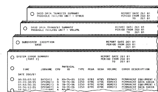
The title of each EREP report appears at the top left side of the page. Titles as they
appear in the EREP printout are shown for:
• System Error Summary (Part 2)
• Subsystem Exception DASD
• DASD Data Transfer Summary
Probable Failing Unit - Volume
Probable Failing Unit - Other
To the right of the title, in the center of the page, are dates. First is the date the
report was printed. Below this are the dates of the period covered by the report.
The dates are based on a day-of-year calendar, where days are counted consecutively
starting with January 1. The date is given as five numbers. The first three numbers
are the days of the year. For example, 261 is September 18. (Many business
calendars also give the day of the year in this manner.) The next two numbers are the
last two numbers of the year, for example, 81.
DASD DATA TRANSFER SUMMARY REPORT' DATE 261 81
~
PROBABLE FAiliNG UNIT - OTHER PERIOD FROM 260 81
TO 261 81
I
I
0
DASD DATA TRANSFER SUMMARY PROBABLE FAILING UNIT - VOLUME REPORT DATE 261 81 PER I.oD FROM 260 81)
TO 261 81
t
0
SUBSYSTEM EXCEPTION REPORT DATE 261 81(
DASD PERIOD FROM 260 81
~
TO 261 81
SYSTEM ERROR SUMMARY REPORT DATE 261 81
(PART 2) PERIOD FROM 260 81
TO 261 81
PHYSICAL }
TIME JOBNAME CPU 10 TYPE PCUA SCUA VOLUME ERROR DESCRIPTION DATE 260/81
00:55:07:52 BATCH13 B XX-74-03 3330 0783 0785 EDSWK3 PERMANEN.T EQU I Pf.1ENT ( 01:31:38:95 DPHSM313 B 78-7C-06 3350 079E 079E Hsr4313 PERMANENT DATA CHECK 01:43:56:36 DN1SM313 B 78-7C-06 3350 079E 079E HSM313 PERMANENT EQUIPMENT ( 01: 5'·1: l13: 84 DPHSM313 A 78-7C-06 3350 079E 079E HSM313 PERMANENT DATA CHECK )
f1,·IJO·""
..
~... " 1 n 1 APC: A RR-..:z.c.. ~.
--
r'rn~lr"'-T n A T A-I - - J - ... -
-
~-
-Figure 1. Titles in System Exception Reports
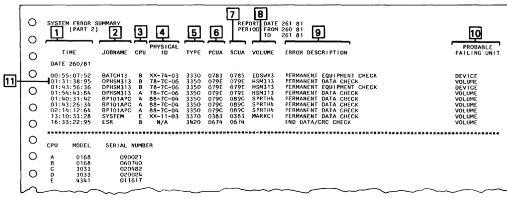
[image:20.626.61.587.308.616.2]How to Read the System Error Summary (Part 2)
Item Description
This column gives the date and time the errors occurred.
The date shown in this column is the date the error occurred. All of the errors in the example were TIME
[I]
on the same day, 260/81 (September 17, 1981).The times shown in this column are for each of the permanent errors. The first four numbers apply to the hours and minutes. For example, the first error occurred at 00:55 (12:55 AM). The next four numbers are seconds and hundredths of seconds.
[I]
This column gives the name of the job in progress when the permanent error occurred. The name isJOBNAME up to eight alphanumeric characters assigned by the programmer. In the example, two data checks occurred while job DPH5M313 was in progress.
The alphabetic characters in this column identify the CPU that received the error record. In the period covered in this report, three CPUs, with alphabetic identifiers B, A, and E, reported errors.
CPU
rIJ
At the bottom of the report, the alphabetic identifiers for all of the CPUs covered by the report are given with their model and serial numbers. In the example, CPU A is a 5/370 Model 168 with serial number 090021. Two of the CPUs, C and 0, had no permanent tape or disk storage errors during the period of the report.This column shows a 6-digit physical 10 required by the EREP program. The first two digits refer to the storage control, the next two to the controller, and the final two to the device (access
PHYSICAL
0
mechanism) in use when the error occurred. For example, three permanent errors occurred when10 running job DPH5M313, while storage control 78, controller 7C, and device 06 were in use. The physical 10 represents either a real physical 10 set with switches or a physical 10 made up especially for the EREP program.
This column gives the product number. In the example, the 3330, 3350, and 3370 disk storage reported permanent errors. The 3420 tape storage also reported errors.
TYPE
[[]
Note: The DASD reports of this same date may include other disk storage types, such as the 3380,which were not included in the System Summary, because they had no permanent errors. The DASD reports include both permanent and temporary errors.
PCUA
III
You do not need the information in this column.This column shows a 3-digit unit address (preceded by a zero) that identifies a channel, storage SCUA
[1]
control, controller, and device. The 5CUA is the address actually used for selection and is theaddress from which sense information was received. In the example, disk storage with 5CUAs of 785, 79E, 89C, and 383 reported data checks.
VOLUME
[]]
This column gives the 6-digit volume serial number that identifies the volume in use at the address when the errors occurred.ERROR
[ru
This column defines the kind of error. They may be equipment or data checks. They are all DESCRIPTION 9 permanent.PROBABLE
[Q]
This column names the probable source of the error as determined by the EREP program. It may beFAILING a channel, storage control, controller, device, or volume. In the sample report, there are two UNIT ! probable failing units of device and seven of volume.
Therefore, for each probable failing unit, we have a job name, a CPU, a physical ID, a product type, a unit address,
and a volume serial number.
Ifthe probable failing unit is a volume, we need only the volume serial number to find the
volume in the two DASD reports.
o
o
o
o
j
SYSTEM ERROR SUMMARY
ITJ
(PART~)JrL~~
PHYSICAL TIME JOBNAME CPU 10DATE 260/81
rul"T---t
o
00:55:07:52 BATCH13 B XX-74-03 01: 31: 38:95 DPHSM313 B 78-7C-06 01:43:56:36 OPHSM313 B 78-7C-06
01:5'~:43:84 OPHSM313 A 78-7C-06 01:40:31:42 BP101APC A 88-7C-04 01:43:26:34 BP101APC A 88-7C-04 02: 111: 12:64 BP101APC A 88-7C-04 13:10:33:28 SYSTEM E XX-11-03 16:33:22:95 ESR B N/A
TYPE
3330 3350 3350 3350 3350 3350 3350 3370 3420
261 81 260 81
[j]
[Q]
261 81
PROBABLE PCUA SCUA VOLUME ERROR DESCRIPTION FA III NG UN IT
0783 0785 EDSWK3 PERMANEN.T EQU I Pt-IENT CHECK DEVICE 079E 079E HSM313 PERMANENT DATA CHECK VOLur·IE 019E 079E HSM313 PERMANENT EQUIPMENT CHECK DEVICE 019E 079E HSM313 PERMANENT DATA CHECK VOLUME 079C 089C SPRTH4 PERMANENT DATA CHECK VOLUME 079C 089C SPRTH4 PERMANENT DATA CHECK VOLUME 019C 089C SPln!!'1 PfRMANrNT DATA CHECK VOll)r4E 0383 0383 MARKCI PERMANENT DATA CHECK VOLUME 0674 0614 END DATA/CRC CHECK VOLur~E
o
o
o
o
o
***************************************************************************************************************************
CPU MODEL SERIAL NUMBER A 0168 090021
B 0168 060740 C 3033 020't82
D 3033 020024 E 4341 011617
Figure 2. System Summary (Part 2) Example
[image:22.615.71.583.50.250.2]How to Read the Subsystem Exception, DASD
Item
PROBABLE FAILING UNIT
FAILURE AFFECT
CPU
PHYSICAL ADDRESS
Description
This column is organized by probable failing unit categories: channel (CHAN)' storage control unit (SCU), controller (CONT), device (DEV), and volume (VOl). All of the units in each category that had errors are listed with probable failing unit identifiers and product type number. The following digit identifiers are used to identify probable failing units. When a physical 10 is used to identify a probable failing unit, the physical 10 represents either a real physical 10 set with switches or a physical 10 made up especially for the EREP program based on an address.
CHAN - channel address digit followed by xx (for example 02xx).
m
SCU - physical 10 of storage control or storage director (for example 18-xx-xx).CONT - physical 10 of controller (for example, xx-22-xx). No controller is shown in the illustration. DEV - physical 10 of controller and device (for example, xx-7C-06).
VOL - serial number of volume (for example HSM313).
For example, there was an error at a device probable failing unit with the physical 10 xx-7C-06 on a 3350. There also was an error on a volume probable failing unit with serial number HSM313 on a 3350. (If both of the errors were reported from the same 3350, the physical addresses, to the right, will be the same.)
rn
You do not need the information in this column.As in the Syst8{l1 Error Summary (Part 2), the alphabetic identifiers in this column identify the CPU
l1J
that receivedth~f!rror
records. At the bottom of the report, the alphabetic identifiers for all of theCPUs covered by the report are given with their model and serial numbers.
This column contains an identifier of a serviceable unit. It is a 3-digit physical address (preceded by
[!]
a zero) or a 6-digit physical 10 for units that have physical IDs (set with switches). For example, the iphysical address 79E, belonging to a 3350, is listed twice, once for device and once for volume.This column gives the total permanent errors and total temporary errors for each unit with errors. For example, scanning down the probable failing unit column to volume, HSM313 had a total of 2 permanent errors and volume MARKCI had 1 permanent and 19 temporary errors.
If the probable failing unit is a volume, the permanent and temporary error is always a data error associated with a read operation.
Values for temporary data errors at a volume do not represent the same thing for all disk storage types.
TOTALS ~. For 3330, 3340, 3344, 3350, and 3370 disk storage types, the value is the total number of PERM TEMP data errors for that volume. For example, volume MARKCI had a total of 19 temporary data
errors. Because there can be only two digits in the temporary column, the highest number of temporary errors printed is 99. Even though 99 is printed, there may actually have been more than 99 temporary errors attributed to that probable failing unit. You may wish to establish limits that will apply to your installation.
• For 3375 or 3380, the value is the number of times the temporary data error rate threshold
was exceeded on that volume. For example, volume VM8001 exceeded the data error rate
threshold one time. These device thresholds are established for the product by IBM, and the threshold value is the same for all devices of that product type.
IMPACT OF You do not need the information in these columns when the probable failing unit is a volume, TEMPORARY [[] because volume errors are always associated with a read operation. (The abbreviations are ERRORS interpreted as follows: EQU CHK = equipment check, SKS = seeks, RD = read, OVRN = overrun.
OTHER refers to items B, C, 0, and I as defined on the top line across the columns.)
USAGE
The usage column gives the total number of seeks (times 1000) and total number of megabytes
rr
read during the period the permanent or temporary errors occurred at that volume. For example,L!.J during the period when volume HSM313 had two permanent read errors, there were 18,000 seek operations and 504 megabytes read.
A statement about unknowns may be printed after the regular listings. Such an unknown indicates
At the bottom of the report is the number of units excluded due to limits that were set by the installation on temporary
errors reported. In the example, there were no units excluded.
o
o
o
o
o
o
o
o
o
o
o
o
o
o
o
o
o
o
i
:U:~W:;A~~CE~Tlo(p
,
~
ij]
5
~~:~~ :~~~
m
:1
~
~
PROBABL PARITY CHK C~CHECK DATA~'SK TE CHK 1-INyg~§9Mgle¥fb~ TEMPORARY ERRORS--- i '---USAGE---FAILING FAILURE PllYSICAL ---TOTALS--- EQU 1000 MB. UNIT AFFECT CPU ADDRESS PERM TEMP CHK SKS RD OVRN OTHER SKS READ *****************************************************************************************************************
CHAN 02XX CHAN/SCU TOTAL 3 3 NIA NIA
A 0280 1 1 3 32
A 02B3 2 2 99 1530
---+---+---+---+---+---+---+---+---+---+---+---+---+
SCU 18-XX-XX CHAN/SCU TOTAl 2 2 NIA NIA3830 B 07115 2 2 3 118
---+---+---+---+---+---+---+---+---+---+---+---+---+
DEV XX-7C-06 DEV TOTAL 1 N/A N/A
3350 B 079E 1 18 504
---+---+---+---+---+---+---+---+---+---+---+---+---+
VOL SPRTH4 DATAXFR TOTAL 3 NIA NIA
3350 A 079C 3 41 392
HSM313 DATAXFR TOTAL 2 NIA NIA
3350 AB 079E 2 18 504
MARKCI DATAXFR TOTAL 19 19 NIA NIA
3370 E 0383 19 19 6 850
BALlBT DATAXFR TOTAL 99 99 NIA N/A
3330 B 0218 99 99 20 920
USPET DATAXFR TOTAL 30 30 NIA NIA
3340 B" 0238 30 30 241 8343
VM8001 DATAXFR TOTAL NIA NIA
3380 C 06-10-00 131 3878
---+---+---+---+---+---+---+---+---+---+---+-"---+---+
UNK UNKNOWN TOTAL NIA NIAB 0709
*****************************************************************************************************************
o UNIT(S) EXCLUDED DUE TO LIMITS CPU
A
B
C
D E
MODEL 0168 0168 3033 3033 4341
SERIAL NUMBER 090021 060740 020482 020024 011617
** ENTRIES WITH AN ASTERJSK INDICATE THAT DASDID CARDS WERE NOT FOUND FOR THE UNIT.
NOTE: "IMPACT OF TEMPORARY ERRORS" IS THF NIIMBER OF TIMES ERROR THRESHOLD HAS BEEN EXCEEDED. NOTE: BLANK ENTRIES INDICATE ZERO VALUES OR NOT APPLICABLE. N/A = NOT AVAILABLE.
NOTE: ZERO ENTRIES INDICATE RECORDS EXIST IN EREP REPORTS BUT THRESHOLDS WERE NOT EXCEEDED. O~~~_
YJIUI'e 3. Subsystem Exception, DASD EUDlpIe
How to Read the DASD Data Transfer Summary
Recall that this report has a
Volume section and an Other section. Only the volume section will be explained. All of
the errors in this section are data errors with volume probable failing units.
FIRST LINE
Item
SECOND LINE
Description
Each volume is listed beginning with the unit address used to select the volume, then the device
[!]
type, and then the volume serial number. For example, the first volume shows Unit Address 79E, Device Type 3350, Volume HSM313.lIJ
For each volume, a CPU and physical address are given. For example, the first volume shows CPU A, Physical Address 79E.FAILURE AT
rJ1
ADDRESS WFor each volume, one or more addresses are given where errors occurred. For count, key, and data devices, addresses are cylinder and head numbers. (The hexadecimal cylinder and head numbers are translated to decimal values for the report, but are in hexadecimal in the sense information.) For example, volume HSM313 at a 3350 with unit address 79E had errors at the address:
Cylinder 0270, Head 28 OR FAILURE r.;,5
AT BLOCK ~ For fixed-block architecture devices, addresses are block numbers (in decimal), and cylinder, head, and sector numbers (in decimal). For example, volume MARKCI at a 3370 selected with unit address 383 had errors at the address:
Block 256413, CCHS 0344-05-35
Below each address is the date and time of the last sense record and 24 bytes of sense information, SENSE
r'41
in hexadecimal. If more than one error is reported for an address, the sense information applies toL:!..J the last error. The only sense information you may need are the last four digits, which contain a
INFORMATION symptom code.
00000000 00000000 00000000 00000000 00000000 OOOOxxxx
Error counts for permanent and temporary data errors are shown on the right side of volume information, with titles above the column.
Values for temporary errors are interpreted as follows. Note that under Temporary, there are two possibilities: Offset Invoked No or Yes.
PERM
[§]
For 3330, 3340, 3350, 3370: The values under Temporary are aI/logged temporary data errors.TEMPORARY r::;1 The value is always listed under Offset Invoked No. The number 0 always appears under Threshold
THRESHOLD LOGGING (Temporary Errors)
L1.J
Logging. For example, Volume USPET had 30 temporary logged data errors ..For 3375 and 3380: The values under Temporary Offset Invoked No are the number of times the data error rate threshold for the volume was exceeded. The value under Temporary Offset Invoked
Yes is the number of times the offset threshold was exceeded. For example, volume VM8001 exceeded the error rate threshold one time and an offset was not invoked.
Only the 3375 and 3380 will have values under the Threshold Logging columns. For these device types, the value under Threshold Logging is the number of errors at that address while the string
(!]
was in logging mode. For example, 3380 volume VM8001 exceeded the temporary data errorthreshold 1 time, and there are 15 errors logged at cylinder 0770, head 01. Also there are 2 errors logged at the other address. Other volumes on the string also may have values under the Threshold Logging column although there are no values under the other error columns. This is because aI/
volumes on the string are placed in logging mode when any volume causes logging mode to begin.
No examples are shown.
DASD DATA TRANSFER SUMMARY
PROBABLE FAILING UNIT - VOLUME REPORT PERIOD FROM 260 81 D~TE 261 81
[1]
TO 261 81 ~o
o
o
1---s-rN-§-r ... lco!!NTS
8,
f61
I i TEMPORARy9 ... - .... _ _~ ,..., OFFSET I NVK 'THRESHOLD • PERM NO YES LOGGING *********************************************************************************** UNITADDRESS 079E DEVTYPE 3350
:--t--t-t----CPU A PHYSICAL ADDRESS 079E VOLUME HSM313 __ ~~~ __ ----FAILURE AT ADDRESS: CYLINDER 0270 HEAD 28
LAST SENSE AT: 260/81 03:54:43:80
0
0
0
0
0
[§]
0
0
0
0
0
0
0
0
0
08000000 020E3C43 010E001C 020AOOOO 00000000 00004943
UN I TADDRESS 079C DEVTYPE 3350 VOLUME SPRTH4 CPU A PIWS I CAL ADDRESS 079C
FAILURE AT ADDRESS: CYLINDER 0160 HEAD 19 LAST SENSE AT: 260/81 01:43:26:34
08000000 020E3C43 00A00013 020AOOOO 00000000 00004943 FAILURE AT ADDRESS: CYLINDER 0217 HEAD 23
LAST SENSE AT: 260/81 02:14:12:64
08000000 020E3C43 00090017 020AOOOO 00000000 00004943
UNITADDRESS 0383 DEVTYPE 3370 VOLUME MARKCI CPU E PHYSICAL ADDRESS 0383
FAILURE AT BLOCK: 256413 CCHS 0344-05-35 LAST SENSE AT: 022/82 13:10:33:28
08015001 58052345 06000002 0003E99E 000601FE 50084945 FAILURE AT BLOCK: 263532 CCHS 0354-00-18 LAST SENSE AT: 022/82 08:55:15:61
08015001 62001250 06000003 00040560 00050200 28000000
UNITADDRESS 0238 DEVTYPE 3340 CPU B PHYSICAL ADDRESS 0238
VOLUME USPET
FAILURE AT ADDRESS: CYLINDER 0081 HEAD 12 LAST SENSE AT: 260/81 01:00:51:03
00001000 2A5BOF53 0051000C 020COOOO 100008BF 10000000
UNITADDRESS 0720 DEVTYPE 3380 VOLUME VM8001 CPU C PHYSICAL ADDRESS 06-10-00
FAILURE AT ADDRESS: CYLINDER 0655 HEAD 00 LAST SENSE AT: 260/81 23:41:29:82
00001000 008F2053 01220000 08951000 0600007A 0001COOO FAILURE AT ADDRESS: CYLINDER 0770 HEAD 01
LAST SENSE AT: 260/81 16:13:20:39
00001000 00023153 01950001 08951000 06000F5A 00400000
2 o o o
2 0 0 0
0 0 0
0 0
0 16 0 0
0 30 0 0
0 0 0 2
0 0 15
0
***********~~*~************~*******************************************************0
0
0
CPU A B C D I·IOOEL 01G8 OlGB 30,")3 3033SERIAL NUMBER 090021
0607'10
020'182
020024
NOTE: CYLINDER/IIEAD/BLOCK NUMBERS ARE DECIMAL VALUES NOTl: UNITADDR[SS IS TilE LOGICAL ADDRESS OF THE DEVICE
Figure 4. DASD Data Transfer Summary Example
I
Volume HSM313Volume SPRTH4
Volume MAR KCI
} Volume USPET
Volume VM8001
[image:26.624.72.547.62.528.2]How to Quickly Find Volume Information
System Error Summary (Part 2)
Subsystem Exception DASD DASD Data Transfer Probable Failing Unit-Volume
0
0
0
0
0
0
0
0
0
0
o
o
o
o
In the following illustration, volume probable failing units are circled in each report.
SYSTEM ERROR SUMMARY (PART 2)
T I ME JOBNAME CPU DATE 260/81
00: 55: 07: 52 01: 31: 38:95 01:43:56:36
01:51~:43:84
01:40:31:42 01:43:26:34 02: 1/1: 12:64 13:10:33:28 16:33:22:95 BATCln3 DPHSM313 OPHSM313 DPHSM313 BP101APC BP101APC BP101APC SYSTEM ESR B B B A A A A E B PHYSICAL 10 XX-74-03 78-7C-06 78-7C-06 78-7C-06 86-7C-04 88-7C-04 86-7C-04 XX-II-03 N/A
TYPE PCUA 3330 0'783 3350 079E 3350 079E 3350 079E 33'70 079C 3350 079C 3350 Of9C 3370 0383 3 /120 0674
REPORT DATE 261 81 PER 100 FROM 260 81
SCUA
e
2::.::
DESCR I PT I ON0785 EDSWK3 PERMANEN.r EQU I P~I[NT CliECK 0"f9E HSI1313 PERMAN EN r DATA CHECK 079E HSM313 PERMANENT EQU I PMENT CHECK 079E HSM313 PERMANENT DATA CIIECK 089C SPRTH4 PERMANENT DATA CHECK 089C SPRTllll PERMANENT DATA CI~[CK
089C SPRHI4 I'[RMAN[NT DATA CHECK 0383 MARKCI PERMANENT DATA CtiECK 06711 END OATA/CRC. CHECK
PROBABLE FAILING UNIT DEVICE VOLU/·IE
****************************************«,**********************************************************************************
CPU MODEL SER I AL NUMBER A 0168 090021 B 0168 060740 C 3033 020482 0 3033 020024 E 4341 011617
SUBSYSTEM EXCEPT ION REPORT DATE 261 81 PER I 00 FROM 260 81 DASD
TO 261 81 B-BUS OUT PARITY CHK C-CHECK DATA CtiK D-DISKETTE CHK I-INVOKED OFFSETS
PROBABLE ---IMPACT OF TEMPORARY ERRORS--- ---USAGE---FAILING FAILURE PllYSICAL ---TOTALS--- EQU 1000 MB. UNI T AFFECT CPU ADDRESS PERM TEMP CflK SKS RD OVRN OTHER SKS READ
*****************************************************************************************************************
CHAN 02XX CHAN/SCU TOTAL N/A N/A
A 0280 3 32
A 02B3 2 2 99 1530
o
~~~--;8:~~:~~-+-~~~~i;~~-+---+-~~~~~----+---+- -2----+----2--+---+---+---+---+--N/;-+--Ni;-+0
0
0
0
'~.0
0
0
0
0
0
0
0
0
3830 B _ 07115 2 2 ::.. 3 118
MARKel DATAXFR 3370
BALIBT DATAXFR ,3330 B
USPET DATAXFR 3340
VM8001 DATAXFR 3380 C
DASD DATA TRANSFER SUM~ PROBABLE FAILING UNIT
0
TOTAL 0383 TOTAL 0218 TOTAL 0238 TOTAL 06-10-00
**.****.)1.*.;":. If-)I .H-*.H-*************************
UN I TADDRESS 079E OEVTYPE 3350 CPU A PIlYSICAL ADDRESS 079E
19 19 99 99 30 30
REPORT DATE 261 61 PER 100 FROM 260 81 TO 261 81
SENSE COUNTS TEMI'ORARY 19 19 99 99 30 30
OF FSET I NVK THRESIIOLD PERM NO YES LOGG I NG
************iC·************************
FAI LUHE AT ADDRESS: CYLINDER 0270 HEAD 26 2 o o
LAST seNSE AT: 260/81 03:511:/13:80
08000000 020E3CII3 O'10EOOIC 020AOOOO 000 0000 000049113 UN ITAODRESS 079C DEVTYPE 3350
CI'U A PIIYS I CAL ADDRESS 079C
FAILURE AT ADDRESS: CYLINDER 0160 H 2 o
LAST SENSE AT: 260/61 01:43:26:3 /1
08000000 020E3CII3 00A00013 020AOOOO 00000000 000049113
Guidelines for Recovery Action
The following guidelines explain how to use the EREP System Exception reports to
interpret an error situation and to determine which error handling function of Device
Support Facilities to use to treat the cause of a data error. You will need to evaluate
the error situation in relation to the circumstances in your installation, such as the
job in progress and the data set being used at the time. For instance, the same error
that would cause you to take prompt action if it occurred in a catalog data set might
be disregarded if it occurred on a volume being used for scratch purposes.
Although guidelines are given, the procedures you implement to handle errors should
be tailored to suit the unique requirements and performance objectives of your
particular installation.
The most effective control of operations can
be
achieved by reviewing error
information and performing recovery on a regular basis, so that error situations do
not accumulate. For most situations, your recovery actions with Device Support
Facilities can be scheduled at a convenient time for minimum impact on system
performance.
Error HandHng During Normal Production
These guidelines apply to errors that occur during normal production with EREP
reports available.
Known Problem
Examine
D
System Summary (Part 2)
---If determined to be permanent disk storage error
Figure 5. Steps in Error Handling
Examine
)
Routine Investigation
Examine
D
Subsystem Exception, DASD
Ifdeterminedlif determined-to be volume
I
to be hardware probableI
probable fail-failing unit I ing unit and and action isI
action is~redl I required Examine
DASD Data Transfer, Volume
---For permanent or excessive temporary data checks, determine location of errors
Use
Device Support Facilities program
~
HardwareCall Service
[image:29.615.29.548.48.699.2]Steps in Error Handling
Print the EREP System Exception reports every day and review them for error information.
Use the System Summary (Part 2), when needed, to investigate a known problem.
If
you have been notified that an error occurred when a particular job was in progress or at a particular time, examine the System Error Summary (Part 2) to determine if the problem may have been caused by a permanent I/O error.
If
there is a permanent error associated with a disk storage, examine the Subsystem Exception, DASD.Use the Subsystem Exception, DASD, to determine whether there are hardware problems requiring a hardware service representative or data errors you should handle with the Device Support Facilities program. Use the report for routine review of possible permanent or temporary disk storage errors and for known permanent disk storage errors found in the System Summary (Part 2).
Are there hardware probable failing units with errors?
These are listed as channel, storage control, controller, and device.Are there volume probable failing units with data errors?
Volumes are listed after all the hardware probable failing units. All errors at a volume are data errors.For each probable failing unit category, look for the device type and probable failing unit identifier. For volumes, this is the volume serial number. Then read across the column to find the total permanent and temporary errors.
With information obtained from the Subsystem Exception, DASD, use these guidelines.
• If
a hardware probable failing unit has a permanent error, call a hardware service representative.• If
a volume probable failing unit has a permanent error, proceed to the DASD Data Transfer Summary.• If
a volume probable failing unit has temporary errors, decide whether the temporary errors are excessive. All temporary errors, up to a maximum of 99, are reported for the 3330, 3340, 3344, 3350, and 3370.If
you establish a threshold for your installation to limit the number of temporary errors reported, this threshold number may then be used as the criterion for judging whethertemporary errors are excessive. For the 3375 and 3380, a listing in the temporary column indicates the established threshold has been exceeded.
If
this occurs one or more times, action with Device Support Facilities is recommended.(Temporary errors and their impact will be discussed later.)
If
the temporary errors are excessive, proceed to the DASD Data Transfer Summary.o
o
o
o
In this example:
m
A device probable failing unit, identified by xx-7C-06, on a 3350 with physical address 79E has one permanent error.m
A volume probable failing unit, identified by SPRTH4, on a 3350 with physical address 79C has three permanent errors.@]
A volume probable failing unit, identified by HSM313, on a 3350 with physical address 79E, has two permanent errors. Note that this is the same physical address as in item[TI.
[!]
A volume probable failing unit, identified by MARKCI, on a 3370 with physical address 383 has one permanent error and 19 temporary errors.[§]
In addition, the following volumes have only temporary errors. VolumeBALIBTon a 3330 has 99, or more, temporary errors. Volume USPETon a 3340 has 30 temporary errors. Volume VM8001 on a 3380 has exceeded the temporary threshold one time.
SUBSYSTEM EXCEPTION REPORT DATE 261 81 DASD PERIOD FROM 260 81 TO 261 81 B-BUS OUT PARITY CHK C-CHECK DATA CliK O-DISKETTE CHK I-INYOKED OFFSETS
PROBABLE ---IMPACT OF TEMPORARY ERRORS--- ---USAGE---FAILING FAILURE PHYSICAL ---TOTALS--- EQU 1000 MB. UNIT AFFECT CPU ADDRESS PERM TEMP CHK SKS RD OVRN OTHER SKS READ
*****************************************************************************************************************
CHAN 02XX CHAN/SCU TOT AL 3 3 NI A NI A
A 0280 1 1 3 32
A 02B3 2 2 99 1530
---+---+---+---+---+---+---+---+---+---+---+---+---+
SCU 18-XX-XX CHAN/SCU TOTAL 2 2 N/A N/A
3830 B 071J5 2 2 3 118
---+---+---+---+---+---+---+---+---+---+---+---+---+
1---1-_-1 DEY XX-7C-06 DEY TOTAL 1 N/A N/A
3350 B 079E 1 18 504
---+---+---+---+---+---+---+---+---+---+---+---+---+
_-+-... VOL SPRTH4 DATAXFR TOTAL 3 N/A N/A
3350 A 079C 3 1J1 392
HSM313 3350
MARKCI 3370
BALIBT 3330
USPET 3340
0
VM8001 3380DATAXFR TOTAL 2 N/A N/A
AB 079E 2 18 504
DATAXFR TOTAL 19 19 N/A N/A
0383 19 19 6 850
DATAXFR TOTAL 99 99 N/A N/A
B 0218 99 99 20 920
DATAXFR TOTAL 30 30 N/A N/A
B 0238 30 30 21J1 831J3
DATAXFR TOTAL N/A N/A
C 06-10-00 131 3878
For the situations from the example, the following actions are indicated:
I. A service representative should be called for the error with the hardware probable failing unit in itemITJ.
2. The DASD Data Transfer Summary should be examined for the permanent errors reported at volume SPRTH4 on
a
3350 in item[I].3. A volume probable failing unit with the same physical address (79E) as in item I1Jhas an error in itemm. Because there is evidence of a hardware problem,
further investigation of the volume problem will be determined by the hardware service representative called for the 3350 as described in itemm.
4. The DASD Data Transfer Summary should be examined for the errors reported at volume MARKCI on a 3370.
Use the DASD Data Transfer Summary to determine the track or block addresses
where data errors occurred on a given volume. These are the tracks or blocks that
should be checked with Device Support Facilities for possible defect skipping or
alternate block assignment.
The way the functions of Device Support Facilities are used depends on the number
of track or block addresses with errors and whether the errors are permanent or
temporary.
Using the volume serial number obtained from the Subsystem Exception, DASD,
find the same volume serial number on the DASD Data Transfer Summary.
Confirm that the device type and physical address are the same as those for the
volume in the Subsystem Exception, DASD.
How many times does Failure at Address appear for that volume? This gives the
number of track or block addresses with data errors on that volume.
Are the errors permanent or temporary? For each track or block address, look to the
right to find whether the data error at that address is permanent or temporary. (The
permanent errors are listed first.)
With tpe information obtained from the DASD Data Transfer Summary, the
following steps can be used as general guidelines. (Later, other considerations will be
discussed and specific guidelines will be given for each device type.)
•
Take measures to protect data, depending on whether errors are permanent or
temporary and on the Device Support Facilities command used. This important
consideration will be discussed later.
•
For devices with a removable disk pack or data module, you may try moving it to
another drive. (There is a risk in moving a 3330 pack.)
If
data errors do not
re.cur, call a hardware service representative to investigate a possible hardware
problem.
For devices with non-removable head and disk assemblies, use the Device Support
Facilities ANALYZE command with the No Scan parameter.
If
a drive problem
is reported in a message, call a hardware service representative to investigate a
possible hardware problem.
.
If
data errors did recur when the pack ormodule was moved or if no hardware
problem was reported when executing the ANALYZE command, proceed to the
next item.
• If
a few addresses have errors, use the Device Support Facilities INSPECT
command to check each track or block that has errors. Obtain the track or block
address from the DASD Data Transfer Summary. (A track address is given as
cylinder and head numbers. In other manuals, the address is sometimes referred
to as cylinder and tracks. They mean the same. A block address for fixed-block
architecture device types is given as a relative block number.)
If
many addresses have errors, or if the home addresses should be rewritten, use
the Device Support Facilities INIT command to check all of the tracks or blocks
on the volume, or call a hardware service representative.
In the example:
Volume HSM313 on a 3350 shows one track address with two permanent data
errors. This same volume was used in the Subsystem Exception, DASD
example, but because there was a hardware probable failing unit at the same
physical address a service representative was recommended. However, if there
was not a hardware probable failing unit with the same address, the one track
on this volume should be checked with Device Support Facilities.
Volume SPRTH4 on a 3350 has permanent errors at two tracks. Both tracks
should be checked with Device Support Facilities. The track addresses are
cylinder 0160, head 19 and cylinder 0217, head 23.
Volume MARKel on a 3370 has one permanent error and three temporary
errors at one block address. This block should be checked with Device Support
Facilities. Whether you check block 263532 because of its 16 temporary errors
depends on the requirements of your installation.
Volume USPET on a 3340 has 30 temporary errors at one track address, which
probably should be checked with Device Support Facilities. The 30 errors
might be because the track had defects in more than one place or because the
same data was frequently read.
Volume VM8001 on a 3380 has no permanent errors, but the temporary error
threshold was exceeded one time, with errors at four tra