USB Driver Embedded Controller Using Embedded C
Ms. Sneha Jaiswal
1, Sushma Dakh
2, Mr. Swapnil M. Sonawane
3,
E & TC Dept Department1, 2, 3,
Genba Sopanrao Moze College of Engg, Balewadi, pune 1, 2 R.M.D Singad College Of Engg Pune 3, University Of Pune1, 2, 3
Pune, Maharasthra1, 2, 3
Email: [email protected] 1 , [email protected] 2, [email protected], 3
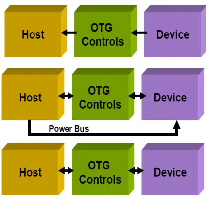
Abstract— USB driver controller stands for USB host. Function of host is to identify USB client. USB O-T-G (ON-THE-GO)
allows two USB devices to talk each other without requiring services of pc’s. All the same OTG appears to be a type of network which interconnected nodes share resources amongst each other without the use of a centralized administrative system Instead, OTG introduces the dual-role device (DRD), capable of functioning either host or peripheral. The perfect charm of OTG is that host and peripheral exchange roles if necessary. Earlier concept of OTG, idea of embedded host was already introduced in world of USB[14] making them better suited to embedded environment than pc with its huge resources, infinite capacity for drivers and application software. USB was developed as solution to pc interconnectivity. USB most popular application for data transfer from system or computer to another. The demand for these products is increasing day by day with popularity; there is necessity for them to transmit both with USB peripherals and directly with each other when PC not available.
Fig1 - OTG UNIVERSE
Key words—Targeted host, USB O-T-G, embedded host, attach detection protocol (ADP), session request protocol(SRP) , host
negotiation protocol(HNP)
1.INTRODUCTION
USB is a new type of I/O interface standard promoted by Compaq, Microsoft, IBM, DEC and ot2her companies n 1995[2,3]
USB has become one of the most popular interface for exchanging data between a host PC and its peripherals. This idea prospered in the mid-1990s defining the cables, connectors and protocols used for connection, communication and power supply between computers and electronic devices. USB has effectively replaced a variety of earlier interfaces,
such as serial and parallel ports, as well as separate power chargers for portable devices.[4]
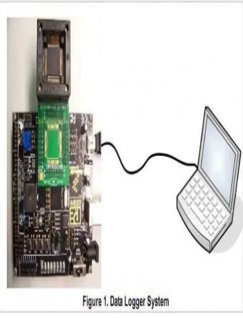
conditions like whether or temperature these conditions can harm the computer, which requires regular maintenance.
Fig. 2 Data logger system
There is several such controller which works on the transfer mediums like GPS, GSM or by using other wireless protocols like Bluetooth, Zig-bee. But they have some limitations like the range of the device from the server, computer where all the data from the several machines is collected for the analysis process. As well as using such systems in the remote areas is quite challenging where the problem of network for the GPS and GSM model occurs. But as per our design the USB embedded controller is a portable device which can be easily mounted on any application system. As we have used the PIC microcontroller which is having inbuilt memory, provides the storage for the data collected from the application system. It becomes very simple and easy to take the back up from one of the machine just by applying the pen drive to the USB embedded controller. One more advantage is this controller is user friendly and the person handling the device does not require the knowledge of the whole computer. Here the data is transferred just by pressing one switch after applying the pen drive. We have chosen PIC microcontroller of family
PIC24FJ128GB110. USB is most popular application for the data transfer from a system or a computer to another. Today many devices that are many PCs in the classic sense have a need to connect directly to peripherals. Printers connect directly with cameras, for example, or mobile phones may need to connect to the USB headsets. These non-PCs have the computing resources to manage a USB host function, but they need to function in ways that differ from standard PC hosts. Although they will provide host capability for some devices, it’s unreasonable to require them to support the full range of USB peripherals.
A targeteted host is only required to support the peripherals on its Targeted Peripheral List.
There are two categories of Targeted Hosts:
Embedded Hosts: A product that has a Standard-A receptacle
supported by a USB Host Controller. Embedded Hosts have a particular set of targeted peripherals, as described in their targeted peripheral list(TPL).
OTG: Device that provides both host and peripheral
capabilities over a single Micro-AB receptacle, as outlined in USBOTG&EHv2.0
So here with the help of PIC microcontroller we are trying to prepare an embedded host. This can be connected rather to connect to the application systems whose backup p the analyzed data is necessary to be taken for the study purpose or for the further processing.
The USB On-The-Go and Embedded Host Supplement to the USB 2.0 specification introduced three new protocols, Attach Detection Protocol (ADP), Session Request Protocol (SRP) and Host Negotiation Protocol (HNP)[2]
2 . Architecture
Standard USB uses a master/slave architecture; in this a USB host plays the role as a the protocol master, and a USB 'Device' plays the role as the slave. The Host only can schedule the configuration and data transfers over the link. Data transfers cannot be initiated by the device, they can only respond to requests given by a host.
USB On-The-Go describes Host/Peripheral role swapping only for the case of a one-to-one connection where two OTG devices are directly connected. Role swapping does not work through a standard hub, as one device will act as the Host and the other as the Peripheral until they are disconnected.
2.1 Specifications
USB OTG is part of a supplement to the USB 2.0 [6] specification originally agreed upon in late 2001 and later revised [7]. The latest version of this supplement also defines behavior for an Embedded Host which has targeted capabilities and the same USB Standard-A port used by PCs.
Super Speed OTG devices, Embedded Hosts and peripherals are supported through the USB On-The-Go and Embedded Host Supplement [8] to the USB 3.0 specification.
2.2 Protocols
The USB On-The-Go and Embedded Host Supplement to the USB 2.0 specification introduced three new protocols[12,13,14], Attach Detection Protocol (ADP), Session Request Protocol (SRP) and Host Negotiation Protocol (HNP).
• ADP allows an OTG device, embedded host or USB device to find or determine attachment or connection status in the absence of power on the USB bus. It enables both insertion based behavior and the possibility for a device to display attachment status. It periodically measuring the capacitance on the USB port to check whether there is another device attached, a dangling cable or no cable. When a change in capacitance is determined, this change should be large enough to indicate device attachment is detected then an A-device will provide power to the USB bus and look for device connection. A B-device will generate SRP and wait for the USB bus to become powered.
[image:3.595.342.551.102.304.2]• SRP request host to start a session, the host activates power bus for the peripheral, and the sessions commence or start. Fig 3 shows the session between the host and the device
Fig. 3 Session request protocol (SRP)
[image:3.595.344.556.390.593.2]• HNP starts as a host and interrogates the peripheral. If peripheral is device, then it remains host and vice versa that is if the peripheral is host then it becomes device. Fig.4 shows the HNP session
Fig 4. Host Negotiation Protocol (HNP) session
host to the printer so that the user's pictures will get printed without juggling cables.
The USB On-The-Go and Embedded Host Supplement to the USB 3.0 specification introduce an additional protocol, Role Swap Protocol (RSP). This achieves the same purpose as HNP (i.e. role swapping) by extending standard mechanisms provided by the USB 3.0 specification. Products following the USB On-The-Go and Embedded Host Supplement to the USB 3.0 specification are also required to follow the USB 2.0 supplement in order to maintain backwards compatibility.
2.2.1 Device roles
USB OTG states two roles of devices: OTG A-device and OTG B-device. This term defines which side supplies power to the link, and which is initially the host. The OTG A-device is a power supplier, and an OTG B-device is a power consumer. The default link configuration is that A-device act as USB Host and B-device is a USB Peripheral. The host and peripheral modes may be exchanged later by using HNP. Because every OTG controller supports both roles, they are often called "Dual-Role" controllers rather than "OTG controllers".
For IC designers, an attraction of USB OTG is the ability to get more USB capabilities with fewer gates. This means many gates to test and debug. Also, most gadgets need to be just a Host, or just a Device. OTG hardware design merges all of these controllers into a single.
2.2.2Backward compatibility
USB OTG devices are backward-compatible with USB 2.0 [13] (USB 3.0 for Super Speed OTG devices) and will behave as standard USB Hosts or Devices when connected to standard (non-OTG) USB devices.
The main exception is that OTG hosts are only required to provide enough power for the products listed on the TPL, which may or may not be enough to connect to a peripheral which is not listed. A powered USB hub may sidestep the issue if supported since this will then provide its own power according to either the USB 2.0 or USB 3.0 specifications.
3. USB IMPLEMANTATION
As per the block diagram shown in Fig 4, it consists of
Fig4: Block diagram of USB Driver Controller.
Microcontroller, LCD display, keypad, USB interface and USB client (pen drive), LED.
Microcontroller is the heart of the embedded controller system which we are going to design.
We have used PIC24FJ128GB110 microcontroller to design the embedded controller. This microcontroller has USB interface and can be act as USB host.
16x2 LCD display is used to show the status of the data being sent to the pen drive from the microcontroller memory which is inputted by the keypad which is interfaced to the microcontroller.
LED is used to indicate the dataflow or the operations done by the microcontroller.
When we give any input from the keypad, that data will be stored in the microcontroller memory in the form of a file. Then when we connect the pen drive to the USB embedded controller the data will be sent to the pen drive.
This transfer of data is the main purpose of our USB embedded controller (USB host). This transfer of data is done by the method of file handling, as we have programmed the microcontroller for this particular operation. The entire code is written in the embedded C language.
Reset pin is also connected to the embedded controller to reset the microcontroller as well as LCD display.
SOFTWARE: In our project we are going to write our code in embedded C in MPLAB X which runs on Windows® OS, MAC® OS and Linux. The below is the algorithm for the implementation of the above idea when developed into a kit.
1) Start the application machine. 2) Power on the circuit.
3) Insert the USB client (pen drive) in the USB slot. 4) When USB gets detected press reset button. 5) Remove USB client (pen drive) from the kit.
6) We can read the log file for analysis using computers.
4. DEVELOPMENT OF USB DEVICE DRIVER
USB devices are having some interfaces [ 2,9,11]. In the USB protocol,here the interface is made up of a number of endpoints representing a basic function and is also which an object USB drvice driver controls.
In this paper, as shown in Fig. 5 the interaction of usb driver with application kit . Here the I/O operation of a user mode program wants to say, read or collect some data from a device can be described as follows [8, 9, 10].
Firstly it calls for windows application programming interface (API) to create file to open the device and create the connection to the device. In the next stage then the subsystem module implements this API by invoking some platform-dependent system service interface to reach a kernel-mode routine.
Then the I/O manager will surround the device driver and then it will create an IRP according to the request information applications will interact with the device and which passes to an entry point in some device driver.
I/O request Packet (IRP) embodies and calls control code to create an IRP (I/O request Packet) with an I/O control code and then calls driver to send the I/O request Packet (IRP) to the USB bus driver.
The USB bus driver subdivides USB request Block (URB) into packets, conveys to the USB bus and sends them to the USB host controller driver.
Drivers even though execute in kernel mode and can therefore talk directly to their hardware using facilities provided by the hardware abstraction layer(HAL) to access the hardware.
hus USB controller will control the communication between the host controller and the USB devices through HAL function calls. Lastly, this operation results to the application in the reverse order after a driver has finished with the I/O
operation.
Fig.5 interaction of usb driver with application
The advantages of the above kit when developed are as follows
It can be used for remote areas where installation of pc is not possible.
Power is saved as we don’t need to supply any extra power supply to the pc.
Also space is saved as there is no need to allocate any special space.
It is a portable device and thus can be easily mounted on any application.
It does not require maintenance. They are not expensive.
They don’t have limitation like the range of the device from the server computer as in case of Bluetooth, Zig-bee, GSM, and GPS.
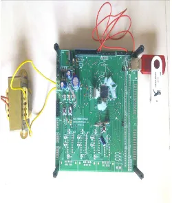
5. RESULT
We have prepared USB driver controller using embedded C which acts as USB host shown in fig 5
We are trying to develop the best driver circuit helpful in data logging in various industries.
The communication between client and host was completed through USB medium.
The circuit requires lower cost than computers for its use. We earned a lot of knowledge on micro-controllers, a deeper & clearer view of the architecture, ports & all other functional blocks was achieved.
We had a peek look at all simple functional parts of the project like the crystal oscillator, reset circuit and their working.
Fig. driver controller using embedded C
6. CONCLUSION
The purpose of the project is to create a USB driver controller which acts as host and helps peripheral to gather data from several applications. This system will be deployed in industries such as data logger where mounting of a computer is not possible. Our circuit will help in reducing the overhead cost and maintenance which is usually required for the installation of computer. An external secondary memory can be added to the circuit to increase the memory capacity of the device so that it can store or transfer data depending on the application
7. FUTURE SCOPE
We have used IC PIC24FJ128GB110 which is having 16384 bytes data memory and 128kb program memory so we can directly use it for industrial purpose for data logging. With the help of this microcontroller IC family we are planning to prepare a universal driver circuit which can be used in various industrial applications such as I2C data logger, USB data logger, SPI data logger and many more.
As our device is portable and doesn’t required separate power supply it can be easily mount in the remote areas for data logging in the projects like wind mill power generation plants.
REFERENCES
[1] www.usb.org/developers/onthego
[2] Anderson D. Universal serial bus architecture. Addison Wesley publishing company, pp. 13-24,1999
[3] Wright Nick, Judd Bob. Using USB as a data acquisition interface. Journal of evaluation engineering . Vol. 43, No. 6, pp. 20-26, 2004
[4] "SuperSpeed USB 3.0: More Details Emerge". 6 Jan 2009.
[5] ^ On-The-Go and Embedded Host Supplement to the USB 2.0 Specification Revision 2.0 plus ECN and errata, July 14, 2011
[6] USB-On-the-Go-Specification Settled. Heise.de, Heinz
Heise.[dead link]
[7] On-The-Go and Embedded Host Supplement to the USB 3.0
Specification Revision 1.0, July 1, 2011
[8] Gereaux, Dean A. USB Device driver. Journal of dr. Dobb, vol. 29, no.4, pp. 60-64, April 2004
[9] Y. P. Su The design of WDM driver based on USb bus. Journal of computer knowledge and technology, No. 36, pp. 142-144 , 2005
[10]Nadolny, Jim, Kelly, Kieran. USB interfaces and EMC. Journal of compliance engineering, vol. 16N.4 pp. 5-10, 1999
[11]Compaq, Hewlett-packard, Intel , lucent, . universal serial bus specification 2.0. Implementers Forum, 2000
[12]"Universal Serial Bus Revision 2.0 specification". Universal
Serial Bus Micro-USB Cables and Connectors Specification. USB Implementers Forum, Inc. 4 April 2009.