46
Design of State Feedback Controller for a Quadruple
Tank Process
S. Nagammai
1,
S.Latha
2 ,N.Gowtham Kannan
2, R.S.Somasundaram
3,B.Prasanna
4Department of EIE1,3,4,KLNCE , Department of EEE2,TCE, Tamil Nadu,India
[email protected], [email protected], gk.nethaji@gmail. com3, [email protected],[email protected]
Abstract- Most of the large and complex industrial processes are naturally Multi Input Multi Output systems.
MIMO systems in comparison with SISO systems are difficult to control due to inherent nonlinearity and due to the existence of interactions among input and output variables. Control of nonlinear MIMO process is cumbersome because nonlinear process does not obey superposition and homogeneity property. This paper presents an implementation of decentralized PID controller and pole placement controller to quadruple tank process with two input and two output model. The process is firstly decoupled through a stable simplified de coupler to attain the benefits of decentralized control techniques. Then, a single input single output PID controller tuning method is used to determine optimal PID controllers for each loop. Finally, performance of the designed controller is measured by the simulation.
Index terms- Multivariable Process; Decentralised PID; state feedback controller.
1. INTRODUCTION
In general for SISO systems different techniques of controller design are proposed and practiced in reality. Now a day’s most of the complex systems are MIMO system. Decentralized (or multi-loop) PID control systems (Chen and Seborg, 2003) are widely used for MIMO control problems in spite of the development of advanced control strategies such as MPC and IMC. In practice, design and implementation of controllers for MIMO system is a difficult task due to the coupling and interactions between inputs and outputs. In last few decades, designing controllers for MIMO systems has attracted lot of researchers. The control objective is to control each output independently, in spite of changes in
manipulated or load variables. Lee et al. proposed the analytical design method of decentralised PID controller for MIMO systems [3]. The design of optimally tuned decentralised PID controller using real coded genetic algorithm is proposed by Donghai Li.et.al.[2]
The proposed work is presented as follows. The section II gives state space modelling of quadruple tank process. In Section III the concepts of design of decoupler is discussed. Section IV explains about the concepts of design of decentralised PID controller and pole placement controller. The simulated results are shown in section V. The work is concluded in section VI.
2. PROCESS DESCRIPTION
A nonlinear mathematical model for the four-tank system is obtained by simple mass balance according to Bernoulli’s equation (Gatzke et al., 2000). The schematic diagram of quadruple tank Process is shown in Fig.1. The differential equations representing the mass balances in this four-tank system are given by equation [1]
(
)
(
)
1 1 3 1
1 3 1
1 1 1
2 2 4 2
2 4 2
2 2 2
2
3 3
3 2
3 3
1
4 4
4 1
4 4
2 2
2 2
1 2
1
2 [1]
d h a a k
g h g h v
d t A A A
d h a a k
g h g h v
d t A A A
k
d h a
g h v
d t A A
k
d h a
g h v
d t A A
γ
γ
γ
γ
= − + +
= − + +
−
= − + +
−
= − +
1
2
2
1
Where hi is the liquid level in tank i; ai is the cross sectional area of connecting pipe of tank i; Ai is the cross sectional area of tank i; νj is the voltage setting of pump j, with the corresponding gain kj ;
γ
j is the portion of the flow into the upper tank from pump j; The process-manipulated inputs are ν1 and ν2(voltage settings of the pumps) and the measured
outputs are
γ
1 andγ
2 (voltages from level47 measured level signals are assumed to be
proportional to the true levels, i.e.,
γ
1=
k h
m1 1 and2 2 2
γ
=
k h
m . The level sensors are calibrated so that km1 = km2 = 1. This simple mass balance model adopts Bernoulli's law for flow out of the orifice. Johansson and Nunes (1998) have shown that the inverse response in the modelled outputs will occur whenγ1+γ2 <1. The nominal operating condition for a minimum phase system is given in Table. IFig.1. Schematic diagram of quadruple tank Process
Table1. Nominal Operating conditions and Parameter values
The non-linear model equations are linearized using Taylor series approximation and the state space model thus obtained is given by equation [2].
3
1 1 3
1
1 4
2 2 2 4 2
3 3 3 4 4 4 1 1 1 2 2 2 1 2 2 2 3 1 1 4 A 1 0 0 A A 1 0 0 A 1
0 0 0
1
0 0 0
γ k 0 A γ k 0 A ( 1 γ ) k 0
A
( 1 γ ) k
0 A h h h h h h h h v v τ τ τ τ τ τ • • • • − − = − − + − − 1 2 3 4
1
0
0
0
y
[2]
0
1
0
0
h
h
h
h
=
The state space model at the nominal operating parameter values for minimum phase system is obtained and given by equation [3]
1
1
2 2 1
3 2
3
4 4
0.016 0 0.042 0 0.08 0 0 0.011 0 0.033 0 0.063
[3] 0 0 0.042 0 0 0.048
0 0 0 0.033 0.03 0
h h h v h h v h h h • • • • − − = + − −
The corresponding linear transfer function matrix is:
1 1 2 2
1 1 3
1 1 2 2
2 4 2
γ c (1 γ )c
s 1 ( s 1 )( s 1 )
(s)
(1 γ )c γ c
( s 1 )( s 1 ) s 1
G τ τ τ
τ τ τ
− + + + = − + + +
For this minimum phase system, the time constants are: is i i i
2h
A
a
g
τ
=
and j j j j k
c , j 1,2
A τ
= =
Substituting the nominal operating parameters values given in table 1, the transfer function matrix is obtained and given by equation [4].
Symbol State/Parameters Minimum phase system 1 2 3 4
,
,
,
s s s sh
h
h
h
Nominal levels [12.4; 12.7; 1.8; 1.4] cm
1 s
,
2 sv
v
Nominal Pump settings [3.00;3.00] cmai Area of the drain in Tank i
[0.071;0.057; 0.071;0.057] cm2
Ai Areas of the tanks [28;32; 28;32]
cm2
1
γ
Ratio of flow in Tank 1to flow in Tank 4 0.7
2
γ
Ratio of flow in Tank 2to flow in Tank 3 0.6
kj Pump proportionality constants
[3.33; 3.35]
48
(
)
(
)(
)
(
)(
)
(
)
11 1 2 21 22
2.6 1.5
62s 1 62s 1 23s 1
G (s) G (s)
[4]
G (s) G (s) 1.4 2.8
30s 1 90s 1 90s 1
+ + +
=
+ + +
3. DE COUPLER DESIGN
The Relative Gain Array (RGA) is first calculated to measure the amount of interaction and to decide the type of pairing (Luyben and Luyben, 1997). Then decentralized PID controller is designed for the system using ZN tuning method.
The steady state gain matrix of the system is,
11 12 11 12
21 22 21 22
g (0) g (0)
k
k
G(0)
g (0) g (0)
k
k
=
=
Multiplying the individual elements of G(0) and
1
G (0)− yields a RGA matrix,
11 22 12 21
11 22 12 21 11 22 12 21 11 12 21 22 21 12 11 22
11 22 12 21 11 22 12 21
k k k k
k k k k k k k k
k k k k
k k k k k k k k
−
− − λ λ
Λ = − =λ λ
− −
The RGA matrix of the minimum phase system is,
11 12
21 22
1.81 0.81 R GA
0.81 1.81
λ λ −
= =
λ λ −
The RGA indicates that the loop pairing y1 with u1 and y2 with u2 is appropriate.
In simplified decoupling, the decoupling matrix is represented to the form
12
21
1
( )
( )
( )
1
d
s
D s
d
s
=
Here, a decoupled response and the de coupler are specified with the structure in the equation given below.
11
22
( ) 0
( ) ( )
0 ( )
eff
p eff
g s
G S D S
g s
=
11 12 12 11
21 22 21 22
( )
( )
1
( )
( )
0
( )
( )
( )
1
0
( )
eff
eff
g s
g s
d s
g
s
g s
g
s
d s
g
s
=
Solving the above matrix we get,
12 12
11
( )
0.025
( )
( )
0.04
g
s
d
s
g
s
S
−
= −
=
+
21 21
22
( )
0.017
( )
( )
0.033
g
s
d
s
g
s
s
−
= −
=
+
The decoupling elements must be stable and should be physically realizable.
4. CONTROLLER DESIGN
4.1. ZN PID controller
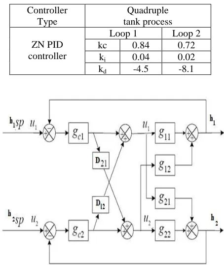
[image:3.595.315.542.322.591.2]A PID controller is widely used in all industrial process. A PID controller takes action based on the value of error. The three mode controller adjusts the manipulated variable so as to minimize error. A decoupling decentralized controller is used. The conventional ZN PID controller tuning parameters are obtained using auto tuner PID block in Matlab simulink control design tool. The designed PID parameters are given in Table.2. The schematic diagram of a MIMO plant withsimplified de coupler and PID controller is shown in Fig.2.
Table 2: ZN PID parameters:
Fig.2. Schematic diagram of a TITO process with simplified decoupler and PID controller.
4.2. Pole placement controller
The concept of feed-backing all the state variables
back to the input of the system through a suitable
feedback gain matrix in the control strategy is known
as the full-state variable feedback control technique.
Using this approach, the desired location of the Controller
Type
Quadruple tank process
ZN PID controller
Loop 1 Loop 2
kc 0.84 0.72
ki 0.04 0.02
49 closed-loop Eigen values (poles) of the system will be
specified. Thus, the aim is to design a feedback
controller that will move some or all of the open-loop
poles of the measured system to the desired
closed-loop pole location as specified. Hence, this approach
is often known as the pole-placement control design.
In order to perform the pole-placement design
technique, the system must be a “completely state
controllable”. Normally, the major disadvantage in
the design of the state feedback controller using
pole-placement is large steady-state error. Therefore, in
order to compensate for this problem, an integral
control is added which eliminates the steady-state
error in the response to the step input. The simulink
diagram of state feedback control for MIMO system
is shown in Fig.3.
The control law is,
u
=
K r t
[
( )
−
x t
( )
]
Now, the state feedback gain matrix is obtained by
solving the equation given below
(
) ( )
(
)
1 2 3 4
det
(
)(
)(
)(
)
0
sI
A
B K
s
p
s
p
s
p
s
p
−
+
= −
−
−
−
=
Where p1,p2 p3 and p4 are arbitrary pole locations chosen to obtain reasonable speed and damping in the
transient response.
The poles are chosen as
[ 0.07 0.07, 0.3, 0.02]
p= − ± j − −
The state feedback controller gains are,
3.17
0.45
0.56
0.54
1.94
4.8
3.85
2.45
k
=
−
−
−
−
−
Fig.3. Simulink diagram of a MIMO plant withstate
feedback controller
5. SIMULATION RESULTS
In order to analyze the performance of the proposed
controllers, the system is simulated using
MATLAB/SIMULINK. The open loop response of
the designed system is shown in Fig.4 and which
indicates that, the open loop system is stable but set
point tracking is not obtainable. The servo response
of ZN tuned PID controller in comparison with state
feedback controller is shown in Fig.5 & Fig.6
respectively for step change in pump voltage. In order
to demonstrate the disturbance rejection capability of
control schemes, simulation studies have been carried
by applying a disturbance input at t=200 sec and ends
at t=400 seconds. The servo regulatory response of
the proposed controller is shown in Fig.7& Fig.8
respectively. The regulatory response shows that, the
state feedback controller is less sensitive to
disturbances.
Fig.4. Open loop response of tank Levels for step input
50 Fig.6. Servo response of state feedback controller
Fig.7. Servo regulatory response for decentralized PID controller
0 200 400 600 800 1000
0 0.5 1 1.5 2
Time in seconds
T
a
n
k
l
e
v
e
ls
i
n
c
m
[image:5.595.71.292.84.569.2]command input Tank 1 level response Tank 2 level response
Fig.8. Servo regulatory response of state feedback Controller
6. CONCLUSION
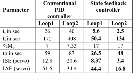
[image:5.595.297.533.126.255.2]The proposed algorithm is demonstrated for a nonlinear Quadruple tank process. It has been shown that, state feedback controller offers better control performance than PI controller. The performance summary is given in Table.3 and which indicates that, the performance of the State feedback controller far exceeds the PID controller’s performance with respect to settling time, peak time and steady state error. The future scope of the work is that, optimization techniques may be used for finding the state feedback gains which ensures superior performance.
Table 3: Comparison of Time domain specifications & Performance indices of quadruple tank process
REFERENCES
[1] Pontus Nordfeldt and Tore Hägglund “Decoupler and PID controller design of TITO systems”, Journal of Process Control, Volume 16, Issue 9, pp . 923-936, 2006.
[2] Prof.S.Nagammai,A.Nandhini,,S.Susitra “Design and implementation of State-feedback Controller for a nonlinear interacting tank process” International Journal of Engineering and Advanced Technology, Volume -2, Issue -4, April 2013.
[3] Truong Nguyen Luan Vu, Moonyong Lee “Independent design of multi-loop PI/PID controllers for interacting multivariable processes”Journal of Process Control ,2010. [4]K.H.Johanson, “The Quadruple Tank Process: A
multivariable Laboratory Process with an Adjustable Zero” IEEE Transactions on Control System Technology, Vol. 8. No. 3, pp. 456-465, 2000.
[5] R.Suja Mani Malar, T.Thyagarajan “Design of Decentralized Fuzzy Controllers for Quadruple tank Process”International Journal of Computer Science and Network Security, VOL.8 No.11, November 2008.
[6] Qamar Saeed, Vali Uddin and Reza Katebi “Multivariable Predictive PID Control for Quadruple Tank” World Academy of Science, Engineering and Technology, 2010
[7]
D.Angeline Vijula, Dr.N.Devarajan “
Design of Decentralised PI Controller using Model Reference Adaptive Control for Quadruple Tank Process, International Journal of Engineering and Technology, Vol 5 No 6 Dec 2013[8] L. Dai and K. J. Åström. Dynamic Matrix Control of a Quadruple Tank Process. In Proceedings of the 14th IFAC, pages 295–300, Beijing, China, 1999.
Parameter
Conventional PID controller
State feedback controller
Loop1 Loop2 Loop1 Loop2
tr in sec 26 40 5.6 2.5
ts in sec 172 408 50.4 134
%Mp 7 7.33 17 17
tp in sec 59 87 26.5 48
ISE (servo) 12.8 20.6 8.37 3.4