Flat-Passband Substrate Integrated Waveguide Filter
with Resistive Couplings
Bin Gao, Lin-Sheng Wu*, and Jun-Fa Mao
Abstract—A lossy filter with resistive coupling is proposed based on substrate integrated waveguide (SIW) resonators, where nonresonating nodes are not required to simplify the realization. The sensitivity analysis ofS-parameter to the resistive coupling coefficient is carried out to determine the parameters of coupling structure and mounted resistors. When resistive couplings are added to the structure, the measured 0.2-dB passband bandwidth increases from 198 to 256 MHz, compared with the case without resistive couplings. At a sacrifice on the additional insertion loss of 1.1 dB, the passband flatness and selectivity are improved significantly. The lossy SIW filter can provide a smaller in-band insertion loss than the microstrip counterparts, because the unloadedQ-factor of SIW resonators is higher than that of microstrip resonators. Moreover, a simpler topology and a less insertion loss are obtained in the proposed resistively coupled SIW filter than those of the lossy filter synthesized with lossy coupling matrix. Excellent agreement between the simulated and measured results is achieved to demonstrate our idea.
1. INTRODUCTION
Filter is one of the most important elements in various microwave systems for radar and communication applications. Filter design has to deal with particular electrical specifications and constraints that also concern its weight and cost. The conventional synthesis procedure is based on the assumption of low-loss or even low-lossless networks [1]. This is approximately satisfied with high-Q resonators. However, the miniaturization and integration may cause significant degradation of unloadedQ-factors of microwave resonators, which bring some disadvantages, such as high insertion and reflection losses in passband, rounding effect of bandedges, and degraded frequency selectivity within transition bands.
In order to overcome the issues in ideal lossless design of low-Q filters, several new techniques are proposed recently. The predistortion technique [1, 2] can improve flatness and selectivity of filters obviously by reflecting more power in the middle passband, which causes its in-band return loss significantly worsened. These filters should usually be cooperated with circulators or isolators.
Another method is proposed in [3, 4] to apply nonuniform-Qresonators for lossy filter design. Based on the utilization of resonators with different prescribed unloaded Q-factors, the method can easily be implemented. In this way, the coupling topology obtained with conventional synthesis method can still be utilized for modified lossy filters. And the resonators which introduce the relatively higher power dissipation especially to the edges of passband should have higher Q-factor. If the required Q-factors cannot be accurately implemented due to some practical limitations, the achieved passband will still be uneven.
In [3], the resistive coupling was first introduced into the lossy filter design. The cross coupling structure with chip resistor was adopted. The matrix synthesis approach with resistive coupling
Received 15 November 2015, Accepted 26 January 2016, Scheduled 1 February 2016
* Corresponding author: Lin-Sheng Wu ([email protected]).
arrays between two ground planes. In [10], a predistorted filter is designed with SIW resonators which have an unloadedQ-factor of 500, and it achieves passband flatness equivalent to its counterparts with the Q-factor of 2000. Based on SIW technology, the filter in [11] realizes transmission zeros in in-line topology by frequency-dependent couplings. A three-pole Chebyshev SIW filter is designed by the lossy matrix synthesis in [12], but the configuration is complicated with two additional nonresonating nodes and three surface mounted resistors.
In this paper, a lossy SIW filter with resistive coupling is proposed to achieve flat passband and simple coupling scheme. The filter structure has only two resistive couplings between resonators, avoiding resistive couplings between the resonators and nonresonating nodes. Based on SIW cavity resonators, the lossy filter has smaller insertion loss than its counterparts with microstrip lines. Through the sensitivity analysis of S-parameters to the resistive coupling coefficient, the parameters of the resistive couplings can be confirmed. From the results, it can be seen that the measured data agree well with the simulated ones.
2. ANALYSIS AND DESIGN
At first, a four-pole Chebyshev filter is designed with SIW resonators for the first reference. This reference filter is centered atf0= 5.0 GHz with a 250 MHz bandwidth. The in-band return loss is set to
20 dB. The SIW resonators are fabricated on a Taconic TLY-5A substrate having a height of 40 mil. The permittivity is εr = 2.17 and its loss tangent tanδ = 0.0009. The copper layer is 35-µm thick and the surface roughness 0.3µm. With this substrate, the unloadedQ-factor of SIW resonator is around 490. The coupling matrixM1is synthesized by the conventional method [13] of ideal lossless cases in Eq. (1),
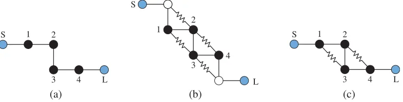
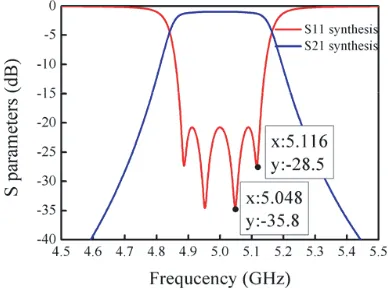
and the coupling topology is given in Fig. 1(a). The filter can be structured as an inline network. The synthesized results of the reference SIW filter are shown in Fig. 2. Its synthesized passband is centered at 5.0 GHz with a 0.2-dB bandwidth of 208 MHz, and its minimum insertion loss is 0.84 dB, due to the
S 1 2
3 4 L S
1
2
3
4
L
S 1 2
3 4 L
(a) (b) (c)
Figure 2. Synthesized results of the reference SIW filter with lossy coupling matrix.
finite Q-factor.
M1 =
⎡ ⎢ ⎢ ⎢ ⎢ ⎢ ⎣
0 1.035 0 0 0 0
1.035 −0.041i 0.911 0 0 0 0 0.911 −0.041i 0.700 0 0 0 0 0.700 −0.041i 0.911 0 0 0 0 0.911 −0.041i 1.035
0 0 0 0 1.035 0
⎤ ⎥ ⎥ ⎥ ⎥ ⎥ ⎦ (1)
A lossy SIW filter synthesized with lossy coupling matrix is designed as the second reference filter. Similarly, this filter is centered at f0= 5.0 GHz with a 250 MHz bandwidth. The in-band return loss is
20 dB. The lossy coupling matrixM2 is synthesized in Eq. (2) with the scaling factorks =kl = 0.333 [6],
and the coupling topology is given in Fig. 1(b).
M2 =
⎡ ⎢ ⎢ ⎢ ⎢ ⎢ ⎣
−0.018i 0.340 −0.018i 0 0 0 0.340 −0.078i 0.907 0.037i 0 0
−0.018i 0.907 −0.096i 0.702 0.037i 0 0 0.037i 0.702 −0.096i 0.907 −0.018i 0 0 0.037i 0.907 −0.078i 0.340 0 0 0 −0.018i 0.340 −0.018i
⎤ ⎥ ⎥ ⎥ ⎥ ⎥ ⎦ (2)
As illustrated by the coupling matrix in Eq. (3) and the coupling topology in Fig. 1(c), two resistive couplings are introduced into the SIW filter to enhance passband flatness and frequency selectivity with simple realization. One resistive coupling is inserted between the first and third resonators while the other resistive coupling is connected with the other two resonators.
M2=
⎡ ⎢ ⎢ ⎢ ⎢ ⎢ ⎣
0 1.035 0 0 0 0
1.035 −0.041i− |m13|i 0.911 m13i 0 0
0 0.911 −0.041i− |m24|i 0.700 m24i 0
0 m13i 0.700 −0.041i− |m13|i 0.911 0
0 0 m24i 0.911 −0.041i− |m24|i 1.035
0 0 0 0 1.035 0
⎤ ⎥ ⎥ ⎥ ⎥ ⎥ ⎦ (3)
For simplification, the coupling topology is assumed with symmetric configuration, i.e.,m13=m24.
The value of m13 should be determined to achieve good flatness in the passband. By choosing some
in-band sampling frequencies, a flat passin-band will be obtained in the case that the variation of their transmission amplitudes is minimized, and the |S21| variation of these samplings is lower than a
threshold.
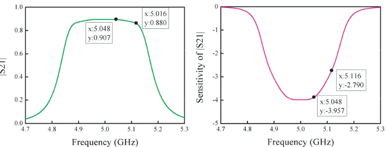
Since the filter has a symmetric response, the reflection zeros of the designed reference SIW filter in the upper half passband are chosen as two sampling frequencies, i.e., 5.048 and 5.116 GHz, as shown in Fig. 2. The synthesized results of |S21| are plotted in Fig. 3. |S21| of the sampling frequencies with
Figure 3. Synthesized results of |S21|and the sensitivity of |S21|to the resistive coupling m13 of the
reference SIW filter.
The sensitivity analysis of|S21|to the resistive couplingm13 is carried out. The sensitivity can be
calculated by
k = ∂|S21|/∂m13 (4)
S21 = −2jA−N1+2,1, A=−jR−sU+M (5) s = j
F BW
f f0 −
f0
f (6)
where FBW is the fractional bandwidth, R an (N + 2)×(N + 2) zero matrix except for R11 = RN+2,N+2 = 1, and U an (N + 2)×(N + 2) identity matrix except for U11 = UN+2,N+2 = 0. The
sensitivity of |S21| to the resistive coupling coefficient m13 is also provided in Fig. 3 as a function
of frequency. The sensitivities at the two sampling frequencies are obtained to be k1 = −3.957 and k2 = −2.790 with the transmission magnitudes of a1 = 0.907 and a2 = 0.880, respectively. Based on
the first-order approximation, we have
m13=m24= a1−a2 k2−k1
= 0.0234 (7)
The resistive coupling can be realized by the circuit shown in Fig. 4(a), which is equivalent to the complex admittance inverter shown in Fig. 4(b). The transmission matrices of circuits in Figs. 4(b) and 4(a) are given by
[ABCD] = 1 0 Y 1 ·
0 ±j
J ±jJ 0 · 1 0 Y 1 = ⎡ ⎢ ⎣ j Y J j J jY2
J +jJ j Y J
⎤ ⎥
⎦ (8)
[ABCD] =
cosθ jZ
0sinθ jsinθ
Z0 cosθ · 1 R 0 1 ·
cosθ jZ
0sinθ jsinθ
Z0 cosθ = ⎡ ⎢ ⎢ ⎣
cos 2θ+jRsin 2θ 2Z0
R(1 + cos 2θ)
2 +jZ0sin 2θ
R(cos 2θ−1) 2Z02 +j
sin 2θ
Z0
cos 2θ+jRsin 2θ 2Z0
⎤ ⎥ ⎥
⎦ (9)
where R is the resistance value of surface mounted resistor, and θ and Z0 are the electrical length
and characteristic impedance of the transmission line connecting the resistor with an SIW cavity, respectively. Then, the expression ofJ can be derived as
J = 4Z0sin 2θ (R+Rcos 2θ)2+ 4Z2
0sin22θ
+j 2R(1 + cos 2θ) (R+Rcos 2θ)2+ 4Z2
0sin22θ
R
J
Y=G+jB Y
(a) (b)
θ θ
Figure 4. Resistive coupling structure: (a) the circuit to be realized; and (b) the equivalent circuit.
(a) (b)
9
10.4 0.2
0.4
Unit: mm
Resistor
b extracted
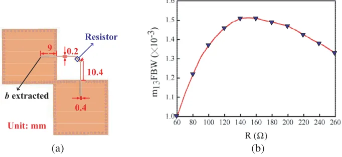
Figure 5. (a) Layout of extracting the value of the susceptance slope parameter b; (b) the value of J as the function of R.
It is seen that when the length of transmission line is not equal to half wavelength, the inverter admittance and resulted coupling coefficient will be complex. In order to obtain the required resistive coupling coefficient, the resistance should satisfy the following equation.
Im (J) = 2R(1 + cos 2θ)
R2(1 + cos 2θ)2+ 4Z2 0sin22θ
=bm13F BW (11)
wherebis the susceptance slope parameter of the SIW resonator, which can be extracted at the tapped location as shown in Fig. 5(a) with the full-wave simulator, ANSYS HFSS. It is obtained thatb= 2.5 S in our design. Fig. 5(b) shows the resistive coupling coefficientm13as the function of resistanceR, where θ = 153◦ and Z0 = 160 Ω. The resistive coupling coefficient at first increases with R to a maximum
value and then shows decreasing trend. When a resistive coupling coefficient m13 is synthesized, the
required value ofR can be solved by
R= 1±
1−4Z02b2m2
13F BW2sin22θ bm13F BW(1 + cos 2θ)
(12)
It is also found that when the length of transmission line is accurately equal to half wavelength, the resistance is simplified to be
R= 1/(m13bF BW) (13)
The resistance is selected to R= 90 Ω as the initial value in our design.
3. RESULTS AND DISCUSSION 3.1. Reference SIW Filter
28 7
1.5
3.12 11 1
10
UnitὉmm
Figure 6. Layout and photo of the reference SIW filter designed with the conventional synthesis method.
Figure 7. Synthesized, simulated and measured responses of the reference SIW filter prototype.
summarizes the critical parameters of the synthesized, simulated and measured responses. It is seen that they are in good consistency. The measured passband is centered at 4.98 GHz, and the bandwidth with the insertion loss varying within 0.2 dB is 198 MHz. The central frequency and 0.2-dB fractional bandwidth are 5.00 GHz and 199 MHz in simulation, respectively. The frequency shift is mainly due to the tolerance of substrate permittivity and fabrication. The measured minimum insertion loss is 1.04 dB, and the in-band return loss is better than 18.9 dB, while the simulated minimum insertion loss is 0.88 dB, and the in-band return loss is better than 19.2 dB. The additional measured insertion loss of about 0.16 dB is introduced by the SMA connectors in measurement.
3.2. Lossy Filter Synthesized with Lossy Coupling Matrix
8.6 0.5 10.9
10 23
48.5
23.3
27.9
Resisitor
3
Unit mm
Figure 8. Layout and photo of the SIW filter synthesized with lossy coupling matrix.
(a) (b)
Figure 9. Comparison of synthesized, simulated and measured results (a) the reference lossy SIW filter synthesized with lossy coupling matrix; (b) the proposed lossy SIW filter with resistive couplings.
Table 2. Coparison of the synthesized, simulated and measured results of the lossy filter synthesized with lossy coupling matrix.
Central Frequency (GHz)
Minimum Insertion Loss (dB)
0.2-dB Bandwidth (MHz)
In-Band Return Loss (dB)
Synthesized 5.00 2.84 266 22.84
Simulated 5.00 2.88 254 21.95
Measured 4.98 3.06 244 21.82
21.82 dB. However, the insertion loss and in-band return loss are 2.88 and 21.95 dB, and the 0.2-dB bandwidth is 254 MHz in the simulated results. The measured flatness is slightly degraded when compared with the theoretical result.
3.3. Proposed Resistively Coupled SIW Filter
256 MHz
244 MHz
198 MHz
Figure 11. Measured normalized transmission coefficients of the two reference SIW filters and the proposed resistively coupled SIW filter.
The comparison of synthesized, simulated and measured responses is plotted in Fig. 9(b) and summarized in Table 3. Its measured passband is centered at 4.99 GHz with a 0.2-dB bandwidth of 256 MHz, while its central frequency and 0.2-dB fractional bandwidth are 5.00 GHz and 257 MHz in simulation, respectively. The simulated minimum insertion loss is 2.05 dB, and its in-band return loss is better than 18.4 dB. The measured insertion loss is 0.1 dB higher than the simulated one. The return loss is also degraded by 1.1 dB in measurement.
The normalized transmission coefficients and measured results of the reference SIW filter, lossy filter synthesized with lossy coupling matrix and the proposed resistively coupling filter are compared in Fig. 11 and Table 4. With insertion loss increased from 0.98 to 3.06 dB, the 0.2-dB bandwidth of the SIW filter synthesized with lossy coupling matrix is improved by 23.2%. By using resistive couplings, the 0.2-dB bandwidth of the proposed lossy SIW filter is broadened from 198 to 256 MHz, i.e., 29.3% improvement of the flat passband, at the cost of increasing the minimum insertion loss by only 1.1 dB when compared with the reference SIW filter. The insertion loss of the proposed resistively coupled filter is 2.10 dB, less than that of 3.06 dB of the lossy SIW filter synthesized with lossy coupling matrix, while their 0.2-dB bandwidths are comparable. And the realization of our proposed filter is more simplified because of avoiding two resistive couplings and two resistors. For the proposed resistively coupled filter, the transmission magnitude of the upper bandedge is a little higher than that of the lower bandedge, as shown in Fig. 11. This is mainly due to the parasitic real part of the coupling coefficient provided by the resistive coupling structure, since the length of transmission lines is not just equal to half wavelength.
Table 3. Coparison of the synthesized, simulated and measured results of the resistively coupled lossy filter.
Central Frequency (GHz)
Minimum Insertion Loss (dB)
0.2-dB Bandwidth (MHz)
In-Band Return Loss (dB)
Synthesized 5.00 2.01 255 20.0
Simulated 5.00 2.05 257 18.4
Measured 4.99 2.10 256 17.3
Table 4. Comparison of the measured results of the two reference SIW filters and the proposed resistively coupled SIW filter.
Central Frequency (GHz)
Minimum Insertion Loss (dB)
0.2-dB Bandwidth (MHz)
In-Band Return Loss (dB)
Reference 4.98 0.98 198 18.9
Lossy 4.98 3.06 244 21.8
Proposed 4.99 2.10 256 17.3
4. CONCLUSION
A lossy SIW filter with two resistive couplings is proposed to improve the passband flatness and frequency selectivity. The resistive couplings between SIW cavities are constructed with surface mounted resistors and planar transmission lines, avoiding the introduction of other resistive couplings between the nonresonating nodes and SIW cavities. The design and realization are simplified, and smaller additional insertion loss is introduced, in comparison with the filter designed with the synthesis method of lossy coupling matrix. The proposed lossy SIW filter has a lower in-band insertion loss with a narrower bandwidth than the microstrip counterparts. Excellent agreement has been observed among the synthesized, simulated and measured results.
ACKNOWLEDGMENT
This work is supported by the National Natural Science Foundation of China under Grants 61370008 and 61361166010.
REFERENCES
1. Cameron, R. J., C. M. Kudsia, and R. R. Mansour,Microwave Filter for Communication Systems: Fundamentals, Design, and Applications, Wiley, Hoboken, NJ, USA, 2007.
2. Williams, A. E., W. G. Bush, and R. R. Bonetti, “Predistortion techniques for multicoupled resonator,” IEEE Trans. Microw. Theory Tech., Vol. 33, No. 5, 402–408, May 1985.
3. Guyette, A. C., I. C. Hunter, and R. D. Pollard, “The design of microwave bandpass filters using resonators with nonuniform Q,” IEEE Trans. Microw. Theory Tech., Vol. 54, No. 11, 3914–3922, Nov. 2006.
IET Microw. Antennas Propag., Vol. 5, No. 8, 928–933, Jan. 2011.
11. Jedrzejewski, A., N. Leszczynska, L. Szydlowski, and M. Mrozowski, “Zero-pole approach to computer aided design of in-line SIW filters with transmission zeros,”Progress In Electromagnetics Research, Vol. 131, 517–533, 2012.
12. Szydlowski, L., A. Lamecki, and M. Mrozowski, “Design of microwave lossy filter based on substrate integrated waveguide (SIW),”IEEE Microw. Wireless Compon. Lett., Vol. 21, No. 5, 249–251, May 2011.
13. Cameron, R. J., “General coupling matrix synthesis methods for Chebyshev filtering functions,”