Contingency Analysis of Fault in Power System
using Soft Computing Technique
K.Rajavelu
1, A.Sathish Kumar
21
Faculty, EEE Department, CK college of Engineering and Technology, Cuddalore
2Faculty, EEE Department, Holy Mary Institute of Science and Technology, Hyderabad.
Abstract:
Voltage stability perform the major role in design and its operation. Major system failures are occur due to voltage variability and breakdown. To meet and compensate the rising power demand of regular usage in modern trends, transmission networks are enormously loaded which create the voltage instability. Contingency analysis is a recognized energy managing tool. It calculate the violation in the transmission line. In this paper a computational controller fuzzy system is suggested to handle the transmission line outage and overload in other branch kind of problems in Power system. The efficiency of power transmission system with fuzzy controller is inveterate by computation of various parameters of transmission bus under different loading situations. For the contingency analysis the transmission power flow several methods have been developed. Fast Decoupled load flow program is the effective method which provides a fast and effective solution to the contingency analysis in the transmission system and also it is incorporate with matrix alteration formula which gives additional advantage for the system.
Keywords
Fuzzy Logic, Voltage stability, Contingency Analysis, non-linear system
1.
Introduction
The power system is a complicated network consist of numerous components like generators, isolators, switches, bus-bars, transmission lines, relay, transformers, circuit breakers etc. If fault occur in any one of these apparatuses in power system throughout its process affects the consistency of the power system and leads to transmission issues and outages. Several methods have been developed in several years to state this problem but computation time has been recognized as the constraint making the process incompetent. Contingency analysis is define the set of event occur in short duration of time and also it identify failure one or more components in power system. The security and consistency is enriched in power system with the help of contingency analysis [1]. Contingency analysis is a
simulation investigation method which associate various problem in power system, come up with the optimal response under circumstances situation [2]. Fuzzy controller is the effective tool to solve the different types of problem in power system [3]. A Fuzzy logic system (FLS) system defines the controlling action of a process by the use of simple If-Then rules [4]. It describes the algorithm for controlling the process as fuzzy relation between information to be controlled which is on the process condition and the controlled action [5,6]. Therefore it provides a linguistic expression or fuzzy model, developed based on human interpretation, human logic and understanding. Instead of providing a mathematical model it provides linguistic expressions for human experience and understandings. The control action of Fuzzy Logic system (FIS) is determined by evaluating linguistic rules with simple set of rules. It does not require mathematical expression or model to define the linguistic rules, but it only depends on complete and systematic understanding of process which needs proper controlling technique. The model used in Fuzzy Logic system (FIS) can be of single input and single output or multi-input and multi-output type. With the use of membership functions and linguistic inputs, fuzzy IF-THEN rules can understand the human’s reasoning. This is done by the use of fuzzy inference systems.
2. Modelling Technology
2.1 MODELLING AND TECHNIQUES OF CONTINGENCY ANALYSIS
2.2 CONTINGENCY INVESTIGATION USING SENSITIVITY ISSUES
The problematic of reviewing several possible outages develops very problematic to solve if it is preferred to present the results rapidly. One of the quietest ways to provide a fast calculation of probable overworks is to use sensitivity issues. These issues show the uneven change in line flows for variations in generation on the network formation and are resultant from the DC load flow. These issues can be resulting in a variety of ways and basically occur in to two types:
Generation Shift Issues [1]
Line Outage Distribution Issues [1]
The generation shift issues are nominated ali and
have the subsequent definition:
(1)
ΔPi is exactly remunerated by an conflicting change in compeers at the reference bus, and that all other producers keep on stable.
aliissue then signifies the sensitivity of the flow on
line l due to a change in compeers at bus i. If the initiator was producing Pio MW and it was lost, it is represented by ΔPi, as the new
(2)
(3)
The line outage distribution issues are used in an alike manner, only they put on to the challenging for overloads when transmission circuits are lost.
(4)
3.
Power Flow Method
This method is centered on DC power flow method to simulate contingencies. DC Load flow method, Line resistances are being neglected but in this method the reactive power flows is ignored for the modelling of system only the real power flows is used.
Impedance Z = r + jx (6) Inverse of impedance Y = G + jA (7)
This method is the real part of the power flow equations are measured, that is the effect of reactive power Q is ignored and bus voltages are presumed to be 1 p.u. The matrix A' is computed on the basis that all the resistances are zero.
3.1 Z-MATRIX METHOD
Z-Matrix is developed with bus impedance matrix which associate with base system and it is adjusted by either removals or additions of lines. Z-matrix method is the inverse method of bus admittance matrix. Z-matrix method of contingency analysis in the power system is to introduce an unreal current into any one of the buses in the transmission system which is associated with the damaged part in the transmission line is to be replaced. In this method, when the component is being removed or replaced, current value of all the bus are set to be zero. This effective practice creates throughout the system a current flow pattern that will change in the same mode as the current flow pattern in the AC load flow solution. Z-matrix method of contingency analysis is very effective as comparable to DC load flow method.
3.2 STABILITY OF VOLTAGE COMPUTATION INDEX
Voltage stability computation method is used to determine the various lead and lags of voltage in the transmission system. The value of L-index arrays from no load condition to Voltage collapse if referred as 0 and 1.
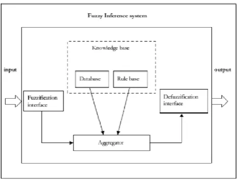
4. Fuzzy Inference System
Fig. 1. Model of fuzzy interference Major components in fuzzy inference systems are: LawBase: encompasses all the fuzzy rules rules. Data Base: used to define the membership
functions.
Aggregator: finalizes the process based on fuzzy rules.
Fuzzy interface: process changes crisp inputs values to linguistic values.
Defuzzification interface: renovates the fuzzy results into crisp output.
Four components perform the major role in fuzzy power flow structure they are fuzzy law base, database, fuzzy interface and defuzzification interface. In fuzzy rule base repetition, the parameters at each knob of the system are fuzzy interface computes and per-unit ∆Hp and ∆Hq. For the crisp input signals in fuzzy these parameters to be selected ,the parameter which refer as maximum power is ∆Hpmax which regulate the mapping range at every iteration it transmutes input signals into an reliable measure of dissertation. The fuzzified input signal switched into a reliable fuzzy signal ∆Hr fuz or ∆Hs fuz with the help of seven linguistic variables
Fuzzy base laws agreed with the linguistic variables: Law 1 : if ∆Hfuz is Large Negative then ∆Xfuz is Large Negative
Law2 : if ∆Hfuz is Medium Negative then ∆Xfuz is Medium Negative
Law3 : if ∆Hfuz is Small Negative then ∆Xfuz is Small Negative
Law4 : if ∆Hfuz is Zero then ∆Xfuz is Zero Law5 : if ∆Hfuz is Small Positive then ∆Xfuz is Small Positive
Law6 : if ∆Hfuz is Medium Positive then ∆Xfuz is Medium Positive
Law7 : if ∆Hfuz is Large Positive then ∆Xfuz is Large Positive
In the fuzzy system at in each iteration of Fuzzy rules, state vector ∆X is completely proportional to power vector ∆H. Fuzzy signals ∆Hfuz are lead to process logic, which produce the fuzzy output signals ∆Xfuz, based on the earlier lawbase and are signified in the fuzzy input signals similar to seven linguistic. ∆Xfuz is refer the output fuzzy signals which directed to the defuzzification interface to perform the following tasks:
In the maximum real or reactive power deviation of the system ,real or reactive power equation are proposed as HI at node -I, angle of voltage (or) magnitude of voltage at node-Width referred as XI and ∆Xfuz is thecenter of the Gaussian membership functions is redesigned in alike way and are listed as:
Large Negative : [∆Xmax/14, -3∆Xmax/4] Medium Negative : [∆Xmax/14, -∆Xmax/2] Small Negative : [∆Xmax/14, -∆Xmax/4] Zero : [∆Xmax/7, 0]
Small Positive : [∆Xmax/14, ∆Xmax/4] Medium Positive : [∆Xmax/14, ∆Xmax/2] Large Positive : [∆Xmax/14, 3∆Xmax/4].
The centroid of area defuzzification policy is accepted and the fuzzy state vector is updated as X
i+1 = X i + ∆XI
5. Software Implementation
5.1 FUZZY LOGIC REGULATOR MEMBERSHIP FUNCTION INPUT SIGNAL:
limit the processing time. Based upon the range positive and negative value iteration time is reduce which increase the system reliability. The fuzzy Membership functions characterize parameter is acceptable in the either form of discrete or continuous in the fuzzy set.
5.2
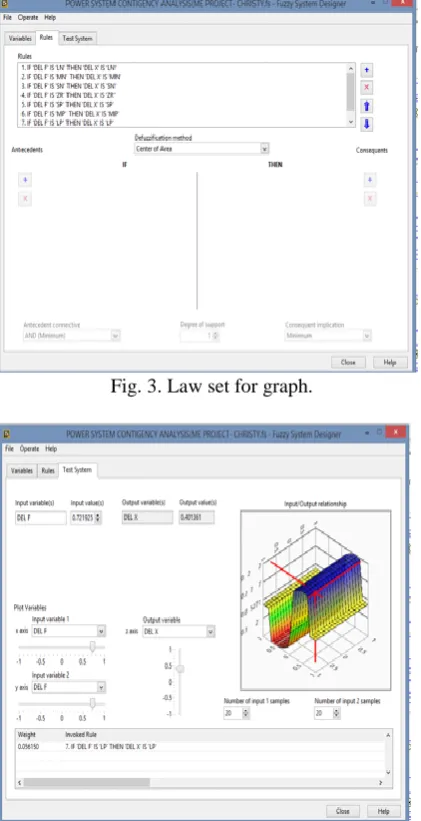
Ouput Value Fuzzy Lawset
The fuzzy rules are framed based upon the if-then conditions. The if-if-then condition rules tuned the signal of sysem. Input of the de-fuzzification ΔH values refers magnititude of both negative and positive signals. The law of fuzzy if-then validate the input signal based upon the fuzzification the regulate the output signal.it implement the shape of the signal and all the fuzzy set is being framed based upon the fuzzy rules.
Fig. 3. Law set for graph.
Fig. 4. Test system Input/ Output relationship. In the Fig.6 shows the test system relationship of input/output signal. Input value is based on the value
assigned for the input variable ΔG similarly the output value is obtained based upon the value assigned for the output variable ΔX.
Fig. 5. Test system Input/ Output relationship.
6
.Conclusion
The line outages of power system contingency status analyzed by using Fuzzy logic. The proposed method offers very valuable and imperative statistics about the possessions of contingency on power system and providing provisions of operational
engineers in taking preceding and necessary preparations and steps to evade any unescapable
states taking place in a system. Power flow method based on Fuzzy logic has been suggested which regulate angles and voltage magnitude at various transmission buses of power system. The fuzzy controller with triangular membership functions is reduce the more number of iterations requirement for the power transmission method. The proposed fuzzy logic based contingency analysis in the transmission system is provide overall CPU time requirement is very less and accurate
References
[1]Mishra, V.J., and Khardenvis,M.D., "Contingency analysis of power system," 2012 IEEE Students'
Conference on Electrical, Electronics and Computer Science, Bhopal, 2012, pp. 1-4.
[2]Ashutash Tiwari and V.Ajjarapu, “Contingency assessment for voltage dip and short term voltage stability analysis”, Bulk power system dynamics and control, Charleston, USA, August 2007.
[3]Ogbuatu.M.O and Ekiokekeme,K., “Minimization of Power System Outage Using Fuzzy Logic Control Mechanism”, International Journal of Latest Technology in Engineering, Management & Applied Science, Vol.7 (8), August 2018, pp. 136-148. [4] Lo.K.L., and Abdelaal,A.K.I., "Fuzzy logic based
Conference on Electric Utility Deregulation and Restructuring and Power Technologies. Proceedings (Cat. No.00EX382), London, UK, 2000, pp. 499-504 [5]Sathish Kumar, A.,“Control of Robot Manipulator
Error using FPDI – IQGA in Neural Network”,
International Journal of Computational and
Theoretical Nanoscience, Vol.13 (3), March 2016, pp. 1740-1748(9).