Interaction between Human and Near-Field of Wireless Power
Transfer System
Maja ˇSkiljo*, Zoran Blaˇzevi´c, and Dragan Poljak
Abstract—In this paper we provide new recommendations for a type of antenna design in applications where a human is present in the vicinity of a wireless power transfer (WPT) system by means of power transfer efficiency (PTE) and specific absorption rate (SAR). The interaction between a homogenous human model and different WPT systems is investigated at 13.56 MHz using spherical mode theory antenna model (SMT-AM) and full-wave numerical analysis. The human model exposure and the performance of the proposed WPT system are analyzed further for some typical scenarios. It is shown that the position in which the human model is closer to the receiver is favorable over the position closer to the transmitter, concerning both PTE and SAR. Also, the consideration of variable receiver load indicates that different levels of SAR coupled by degraded PTE can be expected. The proposed antennas are designed, and proof of concept WPT measurements are carried out.
1. INTRODUCTION
Development of WPT systems today is focused on providing users with spatial freedom, ubiquitous power and global standardization [1, 2]. It is mostly oriented towards charging small electronic devices within few meters at low MHz frequencies. Ubiquitous power and spatial freedom are achieved by near-field resonant WPT systems where small size of electronic devices limits the design of WPT receiver.
Spirals and various other helical geometries used in WPT systems [3–9] are classified as electrically small antennas (ESAs), which generate only the lowest order transversally magnetic (TM) and transversally electric (TE) modes [10–12]. Straightforward recommendations and fundamental limitations of ESA design are given for WPT between identical antennas [6] and different antennas [9] whereas the WPT system model is based on SMT-AM. As WPT systems operate in antennas’ near field at low radio frequencies, various objects and people nearby influence their characteristics and mutual coupling. On the other hand, a certain amount of power is absorbed by human while exposed to near-field of antennas which is strongly dependent on its position and distance from the antennas.
For near-field exposure scenario at frequencies of order MHz, compliance estimation is assessed using SAR rather than incident field [13–15]. Safety guidelines for EM exposure from 3 kHz–300 GHz have been issued by [13] and [14], where whole-body average SAR limit of 0.08 W/kg and a localized SAR limit of 2 W/kg averaged over 10 g of tissue are given for general public. Maximum SAR levels are discussed in [15], where detailed anatomical human models are used. The WPT between spirals is modeled by equivalent circuit theory model and tested with SEMCAD-X. It is worth noting that SAR limitations are given for a human model exposed to a standalone transmitter only. The human exposure assessment is also discussed for a prototype WPT system at 6.78 MHz [16] and at 100 kHz [17]. The influence of a human, modeled as a dielectric box in FEKO, on a WPT system performance is investigated in [5] where a very large rectangular loop is proposed as a WPT transmitter. Near-field
Received 20 June 2016, Accepted 24 August 2016, Scheduled 26 August 2016 * Corresponding author: Maja ˇSkiljo ([email protected]).
WPT system in the presence of lossy materials is analyzed using SMT-AM in [18] but the transmitter is surrounded by a spherical material shell. When material of human tissue characteristics is applied, the degradation of PTE is discussed considering TE and TM mode ESAs.
WPT antenna design is not standardized yet, and since WPT technology is developing and entering our homes rapidly, the goal of our work is to provide new recommendations for the type of WPT antenna design at low MHz frequencies when human is present nearby. For the first time, using SMT-AM and full-wave based numerical analysis in FEKO at low MHz frequencies rather than approaches applied in [3–5, 16–18], we investigate the fundamental aspects of WPT antenna design in the presence of a human model. The WPT system performance and human exposure are analyzed in terms of PTE and SAR, for exposure-compliant and high performance of near field WPT system. In this paper, two types of WPT antennas are considered and compared in order to improve the performance of WPT systems and lower the exposure of a human present in the antenna near field. Here, a transmitter of smaller electrical size that is able to achieve a greater range than the ones in [3–5] is proposed for WPT use. The theoretical and numerical analysis, respectively, is given at a fixed ISM frequency of 13.56 MHz. The interaction between the proposed WPT system and the homogenous human model is investigated using optimum and variable receiver load, and considering the human model position near the transmitter or the receiver. This WPT system is designed, and the proof-of-concept measurements are performed in an indoor environment.
The paper is organized as follows: Some fundamental aspects of WPT system design based on SMT-AM and numerical modeling are given in Section 2; Section 3 provides the numerical analysis of the proposed WPT system and corresponding proof-of-concept measurements; the conclusion is given in Section 4.
2. FUNDAMENTAL ASPECTS OF WPT SYSTEM DESIGN
In this paper we consider human interaction with a WPT system where power is transferred between two inductively fed ESAs in their near field. Antenna theory based on the spherical modes provides insight into all phenomena related to WPT between ESAs in near reactive, radiative and far field, respectively [6]. With clear implications on WPT antenna design and expressions for optimum receiver load derived in [6], one can investigate fundamental limitations (maximum performance) of a specific WPT system. Mismatch between the generator and transmitter antenna as well as the mismatch between the receiver antenna and the load, greatly affects and degrades WPT system performance. This is out of scope of this paper. Here, we consider the best possible WPT system performance when interacting with human and vice versa, the human exposure to the WPT system with optimum receiver load and matched input impedance. Impedance mismatch is considered only in Section 3.2 where different receiver loads are used.
2.1. WPT System Based on SMT-AM
Theory of electrically small antennas, the antennas whose maximum dimension occupies the sphere of diameter 2a less than λ/2π (or ka < 0.5, k = 2π/λ is the wave number) generating only the lowest order radiation modes, divides them into two main types, TE and TM mode ESA [10–12]. They can be described by electrical circuit theory with equivalent RLC parallel or series electrical circuits [11] or, more precisely, by SMT-AM [10, 12] applyingS-matrix depicting receiving, scattering and transmitting properties of minimum scattering antennas [12]. If two different ESAs of the free-space admittances Y1
and Y2 are inductively fed, Y-matrix is convenient for modeling their mutual interaction [12]. Their mutual admittanceYM, obtained from [12], can be written as:
YM =
Re [Y1] Re [Y2]T, (1)
where T is the transmission coefficient depending on antennas’ orientation, their radiation efficiencies
ηrad1,2, mode ratiosα1,2=RTE1,2/RTM1,2 (whereRTE is the TE mode radiation resistance, andRTM is the
orientations, parameterT is given by [6, 9]:
T = 3
2
√
ηrad1ηrad2 1 +
√ α1α2
(1 +α1) (1 +α2)e
−jkd·3 cos2θ−1 1
(jkd)3 + 1
(jkd)2
−sin2θ 1 jkd
. (2)
The maximum power transfer efficiency PTEmax is obtained when the receiver is matched, i.e.,
terminated by the optimum load [6, 9]:
PTEmax= |
T|2
2−Re [T2] + 4{1−Re [T2]} −Im2[T2]
. (3)
Expressions (2) and (3) indicate the importance of the antenna design in WPT systems. For a given distance and frequency specified by the application, in order to achieve maximum WPT performance, it is necessary to boost the antenna radiation efficiency as much as possible [6, 7, 9] and to match their mode ratios if different antennas are used [9]. The problem is that, generally, ESAs exhibit low radiation efficiency because radiation resistance drops rapidly with reducing the antenna size or frequency. For TM mode antennas it drops with f2, for TE mode antennas with f4 [8]) whereas heat loss drops much slower, with f1/2 leading to low radiation efficiency. Also, ESAs that utilize their minimum encompassing sphere the best, tend to achieve better radiation properties than other ESAs that occupy an equal enclosing sphere orka [11, 19]. From the near-field WPT systems point of view, planar spiral antennas (TE mode ESAs) are often used due to their two-dimensional geometry which is convenient to implement in various electronic devices [1, 2, 4, 5]. However, the spirals do not utilize their minimum sphere efficiently and achieve very poor radiation properties, so these WPT systems are limited to short range. By using three-dimensional helical antennas for WPT one can extend the range in the near field [3] as these antennas better utilize the given volume and achieve better radiation properties. Moreover, it is possible to boost their radiation efficiency using multiple-folding method [19]. Multiple-folded four-arm helical antenna is used to approach the maximum performance of WPT system [7]. The spherical helical geometry is known to be the best in utilizing the given volume and achieving great radiation properties [11, 19]. So, multiple-folded spherical antennas can be used for achieving high performance of WPT systems [9].
2.2. Numerical Modeling
Electromagnetic modeling of antennas and WPT systems is performed by FEKO simulation software tool using the Method of Moments (MoM) for wire antenna modeling whereas surface equivalence principle (SEP) is applied for homogeneous dielectric bodies of arbitrary shape. Two WPT systems are simulated to examine the fundamental differences in antenna design and its impact on maximum system performance in free space and in the presence of human model.
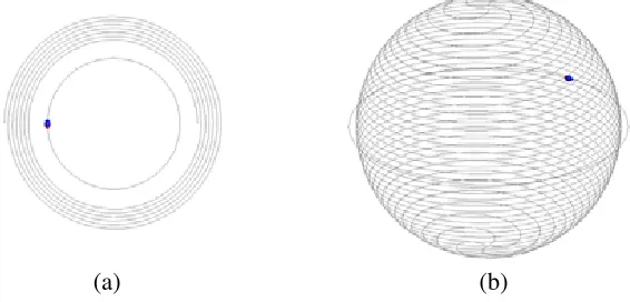
The first one uses two identical inductively fed spiral antennas shown in Fig. 1(a) similar to the ones in [4, 15]. Here, a spiral antenna of 6.5 turns is simulated with an outer and inner radius of 17 cm
(a) (b)
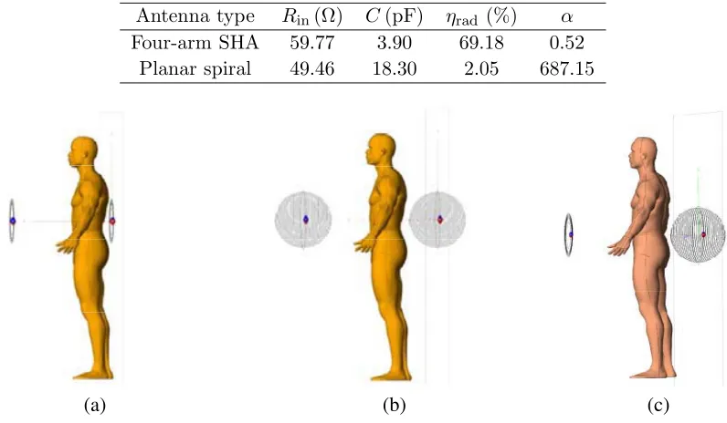
Table 1. Antenna parameters in free space at 13.56 MHz.
Antenna type Rin(Ω) C(pF) ηrad (%) α
Four-arm SHA 59.77 3.90 69.18 0.52 Planar spiral 49.46 18.30 2.05 687.15
(a) (b) (c)
Figure 2. Human model exposed to (a) spiral, (b) four-arm SHA and (c) SHA-spiral WPT system at
d= 1 m.
and 13 cm, respectively. It is inductively fed by a loop with a radius of 10.3 cm. Inductive feed is used for matching the antenna impedance to transmission line impedance by adjusting the coupling between the loop and spiral. The diameter of copper wire for the spiral and its feeding loop is 1.6 mm. The second WPT system consists of two identical inductively fed four-arm SHAs shown in Fig. 1(b). The inductively fed four-arm SHA is first used for WPT in the first part of our study [20]. It is very practical for use in WPT systems because it can achieve 50 Ω impedance match and very high radiation efficiency. The radius of the sphere in our study is 20.8 cm and each arm has 9.1 turns. It is fed by a loop with a radius of 22 cm and the diameter of copper wire for the SHA and its feeding loop is 6 mm. The spiral and four-arm SHA are tuned by a series capacitor and matched to standard 50-Ω impedance in free space at f = 13.56 MHz. Thus, the electrical size of the spiral antenna is ka= 0.048 and of four-arm SHA iska= 0.059. Parameters of both antennas in free space (input resistance Rin, series capacitance
C, radiation efficiency ηrad and mode ratioα), given in Table 1, are used for the SMT-AM calculation of PTEmax by Eq. (3). In FEKO, optimum receiver load was calculated using the Linville method [7].
In this paper a male adult human model is used in all simulations with height of 1.82 m while the antennas are set in the area of his back at height of 1.2 m, shown in Fig. 2, similar to the worst-case scenario in [15]. The human is modeled by homogeneous and isotropic lossy dielectric with relative permittivity εr = 92 and specific conductance σ = 0.419 S/m. These parameters are
calculated according to [21], as two thirds of dielectric parameters that match the human muscle tissue at 13.56 MHz [22]. This human model can be used as a phantom in dosimetric measurements of WPT systems filled with a liquid of specified dielectric parameters. In order to provide a conservative exposure assessment, correction factors or detailed anatomical models can be used [15].
2.3. Power Transfer Efficiency and Specific Absorption Rate
In human-WPT system interaction two parameters are analyzed; PTE as estimation parameter for WPT system performance and SAR to quantify human exposure assessment. PTEmax was calculated using
SMT-AM and simulated in FEKO whereas SAR averaged over 10 g of tissue, SAR10 g, was calculated
in FEKO.
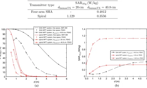
Table 2. Human phantom exposure to standalone transmitter for transmitted power of 5 W.
Transmitter type SAR10 g(W/kg)
dhumanTX = 20 cm dhumanTX= 40.8 cm
Four-arm SHA - 0.4812
Spiral 1.129 0.3556
0 1 2 3 4 5 6
(a) (b)
d (m) d (m)
0.5 1 1.5 2 2.5 3 3.5 4 4.5 5
100
90
80
70
60
50
40
30
20
10
0
PTE (%)
max
1.4
1.2
1
0.8
0.6
0.4
0.2
0
SAR (W/kg)
10 g
SHA WPT system, d = 40.8 cm, FEKOhumanTX
spiral WPT system, d = 20 cm, FEKOhumanTX
spiral WPT system, d = 40.8 cm, FEKOhumanTX
SHA WPT system, free space, SMT-AM SHA WPT system, free space, FEKO SHA WPT system, d humanTX= 40.8 cm, FEKO spiral WPT system, free space, SMT-AM spiral WPT system, free space, FEKO spiral WPT system, d humanTX= 20 cm, FEKO spiral WPT system, d humanTX= 40.8 cm, FEKO
Figure 3. (a) PTEmax of spiral and of SHA WPT systems at θ = 0◦ in free space (SMT-AM and
FEKO) and in the presence of human model (FEKO), and (b) SAR10 g induced in human model at
closest distance and at equal gap to the transmitter in both WPT systems (FEKO).
WPT system, with human model standing at the closest simulated distance to the transmitter. In [20] the cylindrical phantom model was tested in front of the standalone transmitter. The input power is set to 5 W where no mismatch is assumed. The distance dhumanTX between the transmitter and the human model is taken from the center of the transmitter antenna to the center of human model, and distance d between the centers of transmitter and receiver. Note that this is different from air-gap between the antennas’ minimum encompassing spheres because spiral is a two-dimensional and SHA is a 3D antenna. In Table 2, we show the difference in induced SAR10 g when human model is standing at
the closest distance in front of a three- and a two-dimensional transmitter. Here, the closest distance is precisely a very close distance between the human back and the antenna wires where the air gap is cca 5 cm (see Fig. 2), that isdhumanTX = 20 cm for spirals anddhumanTX= 40.8 cm for SHAs. It is observed that at the closest distance to the spiral transmitter dhumanTX = 20 cm, SAR10 g is much higher than
SAR10 g induced in human model standing at the closest distance in front of four-arm SHA transmitter
dhumanTX = 40.8 cm. When the separations between the transmitter and human model measured from
the antenna centers in two cases are equal, SAR10 g is somewhat higher in the case of SHA transmitter.
Figure 3(a) shows the results for PTEmaxin free space (SMT-AM and FEKO) and in the presence
of human model atdhumanTX = 20, 40.8 cm (FEKO). First, from the results in free space for SHA WPT system (black) and spiral WPT system (red), note that a great agreement is achieved between the SMT-AM calculation and FEKO simulation. SHA WPT system achieves much higher PTEmax than
spiral WPT system; for example at d= 2 m one can achieve PTEmax of 90% by SHAs and by spirals
is less degraded. In Fig. 3(b) SAR10 g generally increases with the antenna separationdand approaches
the value of SAR10 gin front of the standalone transmitter for all cases (see Table 2). Consequently, the
human exposure level to standalone transmitter is higher than the one to the matched WPT system. Moreover, if the power transfer between the antennas separated by a distance is efficient, as in the case of four-arm SHA WPT system, then SAR10 g is smaller than in the case of less efficient spiral
WPT system. Correlation coefficients of −0.9853, −0.9943 and −0.9945 calculated between PTEmax
and SAR10 g results for each case (human model at dhumanTX = 40.8 cm in front SHA WPT system,
and at dhumanTX = 20 cm and 40.8 cm in front of spiral WPT system, respectively) confirm that high correlation exists between these parameters and, when PTEmax increases, SAR10 g decreases. Also,
when the human model is positioned at the closest distance to the transmitter’s minimum sphere, it turns out to be much safer to stand in front of the three-dimensional WPT transmitter or system than the two-dimensional one.
Although a conservative assessment of SAR in realistic human models is not investigated in this paper, some important observations can be noted. SAR10 g induced in the homogenous human model
does not exceed the maximum limit of 2 W/kg for the transmitted power of 5 W in all simulations. However, when we simulate these WPT systems transmitting the power of 22 W (as proposed in [1]) with human model positioned at the closest distance to the transmitter and with the antenna separation
d= 2 m, in the matched spiral WPT system the induced SAR10 g exceeds the maximum allowed limit
(2 W/kg) with the value of 4.9 W/kg, whereas in the case of matched SHA WPT system, SAR10 g is
only 0.63 W/kg.
3. THE INTERACTION OF SHA-SPIRAL WPT SYSTEM AND HUMAN MODEL
Based on the SMT-AM WPT model and the results presented in the previous section, we give the example of a WPT system that can achieve higher range in near field and at the same time be safer for nearby people than usually used spiral WPT system. We suggest the use of a highly efficient transmitter, e.g., multiple-folded helical antenna with high radiation efficiency (that still retains a significant Q -factor) and three-dimensional structure that could be settled in places like a chandelier or in some corner of a room. WPT receiver is limited by application and needs to be very compact and small in size, so these antennas could be any kind of spiral with low radiation efficiency and high Q. Here, we use inductively fed four-arm SHA and planar spiral (Fig. 2(c)) presented in the previous section. The
(a) (b)
0 1 2 3 4 5 6
d (m) d (m)
0.5 1 1.5 2 2.5 3 3.5 4 4.5 5
100
90
80
70
60
50
40
30
20
10
0
PTE (%)
max
SHA WPT system, SMT-AM SHA-spiral WPT system, FEKO
spiral WPT system, SMT-AM spiral WPT system, FEKO SHA WPT system, FEKO
SHA-spiral WPT system, SMT-AM
60 50 40
30 20 10 0
PTE (%)
max
0.5
0.4
0.2
0
SAR (W/kg)
10 g
0.3
0.1
human at d = 40.8 cmhumanTX
d (m)
0.5 1 1.5 2 2.5 3 3.5 4 4.5 5
human at d = 20 cmhumanRX
human at d = 40.8 cmhumanTX human at d = 20 cmhumanRX
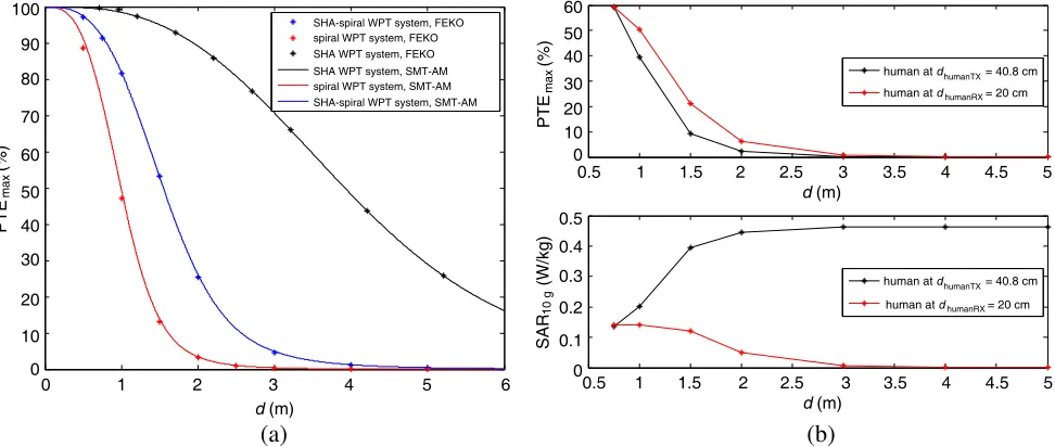
Figure 4. (a) Comparison of PTEmax among two-planar spiral, two-SHA and the SHA-spiral WPT
system and (b) PTEmaxand SAR10 g(FEKO) for SHA-spiral WPT system atθ= 0◦ with human model
PTEmax(calculated by (3) and simulated in FEKO) of SHA-spiral WPT system (blue curve), are given
in Fig. 4(a) and compared with SHA and spiral WPT system consisting of equal antennas. It can be noticed that higher range (or PTEmax at specific distance) can be achieved by matching SHA-spiral
WPT system than by two planar spirals often used for WPT. Also, from expression (2) and Table 1, note that if a better mode ratio match between the transmitter and receiver could be achieved, it would improve the WPT system performance even more. Accordingly, higher PTE would lead to smaller risk for people nearby.
3.1. Human Model Position
Let us consider the influence of the position of human model exposed to SHA-spiral WPT system with optimum load at the receiver. So far we investigated the position of human model at the closest distance to the SHA and to the planar spiral transmitter, and the human model positioned more than a coil radius away from spiral transmitter (dhumanTX = 20 cm, 40.8 cm). As the human model moves away from the transmitter, the influence on its radiation characteristics decreases as well as the influence on PTE and SAR10 g, as expected (Fig. 3, Section 2).
In WPT applications it is very likely to encounter the situation that the human is standing near WPT receiver, so in Fig. 4(b) we give the comparison of the FEKO results for human model in the vicinity of SHA transmitter (dhumanTX = 40.8 cm) and near the spiral receiver (dhumanRX = 20 cm). PTEmaxresults show that higher system performance is achieved when the human model is close to the
spiral receiver than in the case when it is close to the SHA transmitter. It is interesting to note that simulations of WPT systems (not given here) with identical antennas show that PTEmax is the same
regardless the human model is near the transmitter or near the receiver, which is not the case for SAR. The observed results for the exposure of the human model standing at the closest distance to the receiver show that, as the human model (together with the receiver) moves away from the transmitter, SAR10 g
decreases. In WPT systems with identical antennas (spiral or SHA), this is also the case [20]. This implies that the favorable position of a human in near-field WPT systems concerning WPT performance and human exposure is further away from the transmitter.
3.2. Variable Receiver Load
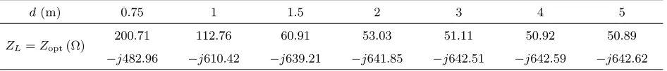
Here we investigate the interaction between SHA-spiral WPT system with different receiver loads and the human model at the closest distance to the transmitter,dhumanTX = 40.8 cm in all cases. The PTE and SAR10 g results simulated in FEKO, are shown in Fig. 5 for optimum load ZL =Zopt, ZL= 50 Ω
(standard transmission line characteristic impedance) and ZL = 1200 Ω (the resistance of 40 W light
bulb in full glow). The antennas are tuned to 13.56 MHz in free space by the same capacitor C from Table 1 and the values ofZopt at the specified antenna separations are given in Table 3 for comparison. From Fig. 5 and Table 3, it can be observed that already atd= 1.5 m the PTE and SAR10 g curves for ZL=Zopt and forZL= 50 Ω are practically merged because the antennas are weakly coupled and the
input impedance is close to the transmitter free space impedance (50 Ω). As the variation of receivers’ load is usual, e.g., in situations where the battery of the device is charging, the change of ZLfrom 50 Ω
to 1200 Ω is simulated. It is important to note that in that case, as a consequence of the impedance mismatch, lower PTE is obtained and higher SAR10 g is induced in the human model. This means that
in case of the load variation one can expect the variation of PTE and varying level of human exposure.
Table 3. Optimum load impedance in SHA-spiral WPT system with human model at dhumanTX = 40.8 cm.
d(m) 0.75 1 1.5 2 3 4 5
ZL=Zopt(Ω) 200.71
−j482.96
112.76
−j610.42
60.91
−j639.21
53.03
−j641.85
51.11
−j642.51
50.92
−j642.59
50.89
d (m)
0.5 1 1.5 2 2.5 3 3.5 4 4.5 5
d (m)
0.5 1 1.5 2 2.5 3 3.5 4 4.5 5
60 50 40 30 20 10 0 PTE (%) 0.5 0.4 0.2
SAR (W/kg)
10 g
0.3
0.1
Z = Z
Z = 50 Ω
Z = 1200 Ω
L L L
opt
Z = Z
Z = 50 Ω
Z = 1200 Ω
L L L
opt
Figure 5. PTE and SAR10 g results for
SHA-spiral WPT system with human model at
dhumanTX = 40.8 cm.
f (MHz)
12 13 14 15 16
0 -5 -10 -15 -20 -25 -30
Reflection coefficients (dB)
spiral measured without human
at d humanRX= 20 cm
four-arm SHA measured without human
spiral measured with human
at d humanTX= 40.8 cm four-arm SHA measured with human
Figure 6. Reflection coefficients in decibels measured at ports of SHA-spiral WPT system without and with human, and photographs of the designed inductively fed four arm SHA (right) and planar spiral (left).
3.3. Measurements of the SHA-spiral WPT System
Proof-of-concept measurements of the SHA-spiral WPT system were performed in our laboratory with a male adult person 1.90 m tall. The goal of these measurements was to test the degree of PTE degradation in an indoor environment when human is present very close to transmitter and receiver (the simulated scenarios). Four-arm SHA (Fig. 6) is wound around the sphere (used for street lights) with a radius of 20 cm made of molded High Density Polyethylene (HDPE) whose relative permittivity ranges from 1–5, and loss tangent from 0.00004–0.001. The SHA arms (with 9.1 turns) are approximately equal in length and rotated 90◦ in respect to each other. The radius of the driving loop is 21 cm, and 3-mm copper tube is used for both loop and SHA. The planar spiral antenna (6.5 turns, outer radius 17 cm and inner radius 13 cm) with its feed loop, shown in Fig. 6, was placed on plywood and made of copper wire with a radius of 0.75 mm. The two antennas were separated by 2.5 m and positioned coaxially (at θ = 0◦) because it is the best orientation of antennas to obtain maximum PTE in the near field [6, 9]. The measurements were conducted by a vector network analyzer VNA Master MS2026C. Due to difference of the practical antenna design and the impact of environment in relation to FEKO simulations in free space, the measured self-resonant frequency differs from the simulated one.
The results for reflection coefficients s11 and s22 in decibels measured at the SHA port and at the planar spiral antenna port respectively are given in Fig. 6. The scenarios with and without human standing at distances from the antennas that correspond approximately to the ones applied in FEKO simulations (40.8 cm from the SHA and 20 cm from planar spiral antenna) are compared. However, the feeding loops were translated from the center of antennas and rotated in order to achieve weak coupling and 50-Ω match like the procedure reported in [4]. The trimmer capacitors were used to tune the antennas to the same resonant frequency, fmeas = 14.63 MHz (see solid black and red lines in Fig. 6). When human appears close to these antennas, the reflection coefficients change, especially in the case of SHA (dashed black line). When input impedance match is assumed, measured power transfer efficiency PTEmeas is calculated from the measured 50-ohm transmission and reflection parameters, s21 and s11,
as:
PTEmeas = |s21| 2
1− |s11|2, (4)
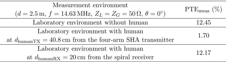
Table 4. Measurement results of the designed SHA-spiral WPT system.
Measurement environment
(d= 2.5 m, f = 14.63 MHz, ZL=ZG= 50 Ω,θ= 0◦)
PTEmeas (%)
Laboratory environment without human 12.45 Laboratory environment with human
at dhumanTX= 40.8 cm from the four-arm SHA transmitter 1.70
Laboratory environment with human
at dhumanRX = 20 cm from the spiral receiver 12.17
PTEmeas drops significantly when a human is positioned close to the SHA, which is manifested in Fig. 6
as a rise of the minimum reflection coefficient relative to the scenario without human. In contrast, this drop of PTEmeas is smaller when a human is close to the planar spiral. If one compares the
measurement results with the simulated ones, it can be noticed that a good agreement is achieved; PTEmeas in a laboratory environment without human agrees well with the PTEmax results atd= 2.5 m
in Fig. 4(a) (blue line) whereas PTEmeasin the cases when a human is present agrees with the conclusions
derived from Fig. 4(b) in Section 3.1. about the degree of PTEmaxdegradation regarding the position of
human. The results for PTEmeas with human at dhumanTX = 40.8 cm also agree with the corresponding
simulation results in Fig. 5.
4. CONCLUSION
In this study, the interaction of a human model and WPT systems is investigated using two parameters, power transfer efficiency (PTE) and specific absorption rate (SAR). The fundamental differences are shown between efficient and less efficient WPT antenna designs, respectively, based on spherical mode antenna theory and the assessment of human exposure to these WPT systems using FEKO simulations. It is demonstrated that by efficient four-arm SHAs it is possible to achieve greater range in free space and in the presence of the human model than by planar spirals. Also, induced SAR10 g is generally
smaller when human model is exposed to a four-arm SHA WPT system, than in the case of a spiral WPT system or a standalone transmitter.
An example of WPT system design is given conforming to applications and recommendations related to human-WPT system interaction. The transmitter is an efficient four-arm SHA, and the receiver is a less efficient planar spiral, convenient for implementation in small electronic devices. Some typical scenarios of interaction between a human and SHA-spiral WPT system are investigated. The human model is simulated at a very close distance to the transmitter and to the receiver. The position of the human model near the receiver is shown to be a more favorable concerning both, PTEmax, and
SAR10 g. Also, the simulation results for variable receiver load indicate that different level of human
exposure and degraded power transfer efficiency can be expected when the battery of the device is charging. The simulated antennas are manufactured in our lab, and WPT between them is tested, as well. Proof-of-concept measurements confirm the conclusions derived from the simulation results.
ACKNOWLEDGMENT
The authors thank Dr. Zlatko ˇZivkovi´c for his help with measurements and valuable suggestions.
REFERENCES
1. Alliance for wireless power, https://www.rezence.com. 2. WiTricity, http://www.witricity.com.
4. Sample, A., D. Meyer, and J. Smith, “Analysis, experimental results, and range adaptation of magnetically coupled resonators for wireless power transfer,” IEEE Trans. Ind. Electron, Vol. 58, No. 2, 544–554, Feb. 2010.
5. Yuan, Q., Y. Chen, L. Li, and K. Sawaya, “Numerical analysis on transmission efficiency of evanescent resonant coupling wireless power transfer system,” IEEE Trans. Antennas Propag., Vol. 58, No. 5, 1751–1758, May 2010.
6. Lee, J. and S. Nam, “Fundamental aspects of near-field coupling small antennas for wireless power transfer,”IEEE Trans. Antennas Propag., Vol. 58, No. 12, 3442–3449, 2010.
7. Yoon, I. J. and H. Ling, “Realizing efficient wireless power transfer using small folded cylindrical helix dipoles,”IEEE Antennas Wireless Propag. Lett., Vol. 9, 846–849, 2010.
8. Tak, Y., J. Park, and S. Nam, “The optimum operating frequency for near-field coupled small antennas,”IEEE Trans. Antennas Propag., Vol. 59, No. 3, 1027–1031, Mar. 2011.
9. Skiljo, M. and Z. Blazevic, “Spherical helices for resonant wireless power transfer,” International Journal of Antennas and Propagation, Vol. 2013, 1–12, Article ID 426574, 2013.
10. Chu, L. J., “Physical limitations of omni-directional antennas,”Journal of Applied Physics, Vol. 19, 1163–1175, 1948.
11. Wheeler, H. A., “Fundamental limitations of small antennas,” Proc. IRE, Vol. 35, No. 12, 1479– 1484, Dec. 1947.
12. Wasylkiwskyj, W. and W. K. Kahn, “Scattering properties and mutual coupling of antennas with prescribed radiation pattern,” IEEE Trans. Antennas Propag., Vol. 18, No. 6, 741–752, 1970. 13. Yoon, I. J. and H. Ling, “Investigation of near-field wireless power transfer in the presence of lossy
dielectric materials,” IEEE Trans. Antennas Propag., Vol. 61, No. 1, 482–488, 2013.
14. IEEE Std C95.1 IEEE Standard for Safety Levels With Respect to Human Exposure to Radio Frequency Electromagnetic Fields, 3 kHz to 300 GHz, IEEE SCC28, IEEE Standards Department, International Committee on Electromagnetic Safety, The Institute of Electrical and Electronics Engineers, NY, 1999.
15. ICNIRP, “Guidelines for limiting exposure to time-varying electric, magnetic and electromagnetic fields (up to 300 GHz),” Health Phys., Vol. 74, 494–522, 1998.
16. Christ, A., M. G. Douglas, J. M. Roman, E. B. Cooper, A. P. Sample, B. H. Waters, J. R. Smith, and N. Kuster, “Evaluation of wireless resonant power transfer systems with human electromagnetic exposure limits,” IEEE Trans. Electromagn. Compat., Vol. 55, No. 2, 265–274, Apr. 2013.
17. Chen, X. L., A. E. Umenei, D. W. Baarman, N. Chavannes, V. De Santis, J. R. Mosig, and N. Kuster, “Human exposure to close-range resonant wireless power transfer systems as a function of design parameters,”IEEE Trans. Electromagn. Compat., Vol. 56, No. 5, 1027–1034, Oct. 2014. 18. Nadakuduti, J., M. Douglas, L. Lu, A. Christ, P. Guckian, and N. Kuster, “Compliance testing
methodology for wireless power transfer systems,” IEEE Trans. Power Electron., Vol. 30, No. 11, 6264–6273, 2015.
19. Best, S. R., “The performance properties of electrically small resonant multiple-arm folded wire antennas,”IEEE Antennas Propag. Mag., Vol. 47, No. 4, 13–27, 2005.
20. Skiljo, M. and Z. Blazevic, “Interaction between humans and wireless power transfer systems,”
Proc. Soft COM, 15–18, 2014.
21. Hasgall, P. A., F. Di Gennaro, C. Baumgartner, E. Neufeld, M. C. Gosselin, D. Payne, A. Klingenb¨ock, and N. Kuster, “IT’IS Database for thermal and electromagnetic parameters of biological tissues,” Version 2.6, www.itis.ethz.ch/database.