PROCESSING OF COMPOSITES USING VARIABLE AND FIXED FREQUENCY MICROWAVE FACILITIES
H. S. Ku and T. Yusaf
Faculty of Engineering and Surveying University of Southern Queensland (USQ) West Street, Toowoomba 4350, Australia
Abstract—This paper starts with the characteristics and advantages of microwaves processing. The shortcomings of fixed frequency, typically at 2.45 GHz were also mentioned. On account of this, the newly developed variable frequency microwave (VFM) fabrication was mentioned and adopted in place of the fixed frequency process. Two cases of fixed frequency microwave processing of materials were described; the characteristics and pros of each case was mentioned and commented. Two cases of processing materials using variable frequency microwave facility (VFMF) were mentioned; the advantages and limitations of each case were discussed. The microwave processing of materials provides improved mechanical, physical and electrical properties with much reduced processing time. Furthermore, variable frequency microwave processing is more superior to its fixed frequency counterpart except that the cost of the facilities of the former is much higher than the latter at this point in time but it appears that the price will drop in the coming ten years.
1. INTRODUCTION
are hard to process; a reduction in the environmental impact of materials processing; economic advantages through energy savings, space, and time; and an opportunity to produce new materials and microstructures that cannot be achieved by other methods. The use of microwave irradiation for materials processing has the potential to offer similar advantages in reduced processing times and energy savings [3]. The characteristics of microwave processing of materials include:
• selective heating;
• rapid heating;
• controllable electric field distribution;
• penetrating irradiation;
• self-limiting reactions.
These characteristics bring about unfavorable effects in materials processing. Bulk materials with significant ionic or metallic conductivity cannot be efficiently processed because of inadequate penetration of the irradiation. Insulators with low dielectric loss are difficult to heat from room temperature to the required temperature on account of their limited absorption of the incident power. Materials with loss factors that vary significantly with temperature during processing will often lead to hot spots and thermal runaway. It can be argued that the most likely candidates for future production-scale applications which will take full advantage of the unique characteristics of microwaves include polymers, ceramics, adhesives, composite joining and catalytic processes. The savings envisaged include timesaving, higher yield, and environmental friendliness [4]. In crosslinking composites, autoclave curing is suitable for individually cured parts made of thin, uniform laminates. Autoclave curing is less suitable when the parts are large, thick or have uneven dimensions, or when several different parts are cured simultaneously. In these cases, the unavoidable temperature gradients inside the autoclave and the thermal inertia of the autoclave make it difficult to ensure that the parts are cured uniformly and completely. Microwave curing offers the possibility of uniform, complete and fast economical cure regardless of the geometry of the part [5]. This paper reviews and comments microwave processing of composite materials using fixed as well variable frequency microwave energy.
2. MATERIALS AND MICROWAVES INTERACTIONS
which in turn generates a magnetic field and the process repeats. The frequency ranges from 300 MHz to 300 GHz. Frequency bands reserved for industrial applications are 915 MHz, 2.45 GHz, 5.8 GHz and 24.124 GHz. In general, microwave processing systems consist of a microwave source, a circulator, an applicator to deliver the power to the load, and systems to control the heating. These are shown in Figure 1. Most applicators are multimode, where a lot of field patterns are excited simultaneously [1].
Figure 1. Microwave system for materials processing.
The material properties of greatest importance in microwave processing of a dielectric are the complex relative permittivityε=ε− ε and the loss tangent, tanδ= εε. The real part of the permittivity, ε, sometimes called the dielectric constant, mostly determines how much of the incident energy is reflected at the air-sample interface, and how much enters the sample. The most important property in microwave processing is the loss tangent, tanδ or dielectric loss, which predicts the ability of the material to convert the incoming energy into heat [6]. The absolute permittivity of a vacuum is ε0 and it is
determined by the speed of light C0 and the magnetic constant µ0,
which are linked together byC0µ0ε0= 1. The relative permittivity εr
of a material is equal to εabs
ε0 , where εabs is the absolute permittivity
of the material. Materials do not contain magnetic components like composites discussed respond only to the electric field [2].
field causes dissolved ions of positive and negative charges to migrate towards oppositely charged regions. This results in multiple billiard-ball-like collisions and disruption of hydrogen bonds with water, both of which result in the generation of heat [2, 6].
3. VARIABLE FREQUENCY MICROWAVES (VFM)
The frequency of microwave oven in our kitchens is fixed at 2.45 GHz and magnetrons are used for the generation of microwaves. The fixed frequency microwave facility mentioned in this paper is also 2.45 GHz. Variable frequency microwave (VFM) technology is a new technique for microwave processing introduced to solve the problems brought about by fixed frequency microwave processing. The technique has been applied to advanced materials processing and chemical synthesis. It offers rapid, uniform and selective heating over a large volume and at a high energy coupling efficiency. This is accomplished using preselected bandwidth sweeping around a central frequency employing tunable sources such as travelling wave tubes as the microwave power amplifier. Selective heating of complex samples and industrial scale-up are now viable [7, 8]. At the heart of the VFM technology is a high power, broadband, helix travelling wave tube (TWT), which has been used in the VFM furnace (VFMF) constructed to date [9]. During VFM processing, a variable frequency of microwaves would be launched into a multimode cavity sequentially for the duration specified, e.g., one millisecond.
changed without changing the power. The microwave incident power can be pulsed or continuously varied to provide some control over the heating profile of the workload [10]. An example for this is to reduce the colonies of bacteria on a piece of meat. Frequency of the irradiation can be selected to couple best with the dielectric properties of the bacteria but not the meat itself. The process will kill the bacteria on the meat and extend the shelf life of meat without cooking it [10, 11].
(a) (b)
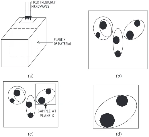
(c) (d)
Figure 2. Non uniform heating by fixed frequency microwaves. (a) Multiple reflections of incident microwaves resulting in a field pattern within the cavity, (b) Field pattern at plane X due to fixed frequency microwaves (black represents field strength), (c) Sample at plane X of the material, (d) Non uniform heating in sample at plane X due to non uniform electric field.
4. FIXED FREQUENCY CURING OR PROCESSING OF COMPOSITE MATERIALS
Case 1
(a) (b)
(c) (d)
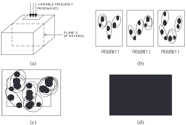
Figure 3. Uniform heating by fixed frequency microwaves. (a) Multiple reflections of incident microwaves resulting in a field pattern within the cavity, (b) Field patterns at plane X with three different frequencies variable frequencies (black represents fieldstrength), (c) Sample at plane X of the material, (d) Uniform heating in sample at plane X due to non uniform electric field.
MAGNETRON
WAVEGUIDE
MOVEABLE PLUNGER
WAVEGUIDE SLIT
TEST PIECE
323 1109
MICROWAVE OVEN CAVITY
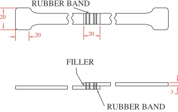
Figure 4, the incident waves are generated by the magnetron located on the top of the equipment. The microwaves travel downwards through three sections of WR340 waveguide and interact with the test pieces located in the second section before being reflected back by the top face of the adjustable plunger. The test pieces are shown in Figure 5, which are the two halves of standard test pieces for composite materials. The lapped areas were first roughened by rubbing them against coarse, grade 80, emery paper. They were then cleaned by immersing them in methanol and allowed to dry in air before applying 1.5 to 2 cubic millimetres of Araldite (Part A was 100% liquid epoxy resin; Part B was 8% amine) onto both surfaces. The lapped area was made 10 mm×20 mm. After applying the filler, the two pieces were tightened by a dielectric band, which encircled the lapped areas four times as depicted in Figure 5. After tightening with a dielectric band, the two halves of the test pieces were positioned in the slot across the waveguide as illustrated in Figure 6. It was estimated that the pressure applied by the dielectric band to the test pieces was 4N [12].
FILLER
RUBBER BAND
3 20
20
20
RUBBER BAND
Figure 5. Test pieces tightened by a dielectric band.
One composite material, thirty three percent by weight glass fiber reinforced polystyrene [PS/GF (33%), was joined and its lap shear strength tested. A Shimadzu tensile testing machine was used for the lap shear test. A load range of 2000 N and a load rate of 600 N per minute were selected for the test [13–16].
20 40
152 43.18
TE MODE CAVITY
10
CLAMP
SPRING
ALUMINUM BLOCK
INTERFACE
WAVEGUIDE
SECTION A - A'
SLIT
TEST PIECE
MICROWAVE A'
A
Figure 6. Test pieces in position.
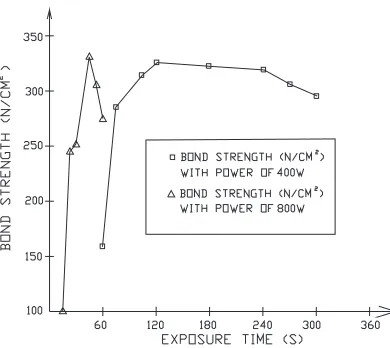
Figure 7. Lap shear strength of PS/GF (33%) joined by fixed frequency microwave (2.45 GHz) in a slotted rectangular waveguide using 5-minute two parts Araldite.
was 45 seconds and it exceeded the ambient conditions cured lap shear strength by 19%, but the time required was only 1.25% of its rival [12, 17–19]. The lower bond strength obtained, for test pieces exposed to microwaves for over 2 minutes and 45 seconds for power levels of 400 W and 800 W respectively, might be due to over-curing of the adhesive [17].
With some exposure durations, the lap shear strengths were higher than those cured conventionally because the parent material might have melted and diffused into the primer or interface and this was reflected in the softening of the lapped area after it was just removed from the applicator and examined using low power microscopy. This was further confirmed by the use of scanning electron microscope (SEM). The HAZ (heat affected zone) seemed to be confined to the lapped area, which could be bent by hand easily and outside which the warming and heating effect of microwave energy could not be felt. The tensile tests revealed that sixty percent of the failures were due to the adhesive and took place at the joints [11, 20–22].
Case 2
Liu et al. used fixed frequency (2.45 GHz) microwave oven to cure nadic-end-capped polyimide precursor (RP-46 resin). The maximum power of the oven is 1200 W which can be adjusted between 0 to 100%. Both neat resin samples and glass cloth and hybrid glass clothCgraphite cloth RP-46 resin composites were studied. The variables studied in this project included power level, temperature, mold material (for placing the samples), vacuum and low pressure. Three types of moulds were employed to contain the composites; the moulds together with their contents were then placed in the cavity of the microwave oven. The first type of mold was alumina mold; the second one was Kapton vacuum bag sandwiched between ceramic plates (soapstone); the last one was Telfon mold. Four types of composites in terms of lay-up, material and state of resin were placed in the three types of moulds for curing. They are processed in different microwave conditions in terms of power input and duration of exposure to microwave irradiation [22].
up the samples, which could not absorb all the microwaves propagated to the cavity and hence some energy was lost to the other parts of the cavity and the surrounding. The cured samples were cut into 6.35 in (l)×0.635 in (w)×0.625 in (t). They were then subjected to three point bending tests with crosshead speed of 1 mm/min, the maximum load set between 22.7 to 90.0 kg and the recorder’s chart speed set at 10 cm/min. It was found that the power inputs were not enough to fully cured the resins as indicated by the glass transition temperature and the infrared spectra of the specimens. The one with least energy input exhibited a flexural strength of 386 N/mm2 and modulus value
of 19.4kN/mm2 respectively and failed between piles. The one with
most energy input showed the best mechanical properties [22].
Three stacked samples of glass cloth-RP-46 resin prepreg and graphite cloth-RP-46 resin prepreg containing 57% RP-46 resin were located in four vacuumed Kapton bags. Each of the stacking contains four layers of alternating layers of glass and graphite prepregs. Three plies of glass cloth were impregnated into RP-46 imidized resin and then located into three different vacuumed Kapton bags. Each bag containing the lay-up was positioned between two pieces of Aremcolox machined ceramic plates (each 25.4mm thick) which were good absorbers of microwave energy; the heat produced due to microwave absorption was conducted to the lay-up inside the vacuum bag. The microwave processing conditions were similar to the first four samples. However, the samples received more energy than the first four samples because of the extra energy supplied to them from the ceramic plates through conduction. The energy input varied from 900 kW to 2,500 kW which was less than that of the first four samples. Furthermore, the crosslinking of the composites had completed. The mechanical properties were also much better. It can be argued that the ceramic plates absorbed a large amount of microwaves and converted into heat which was then conducted to the last 4specimens [22].
temperatures. Two samples of glass cloth and graphite cloth prepregs were fully cured in 50 minutes and their densities were higher than the previous ten samples; this implied that their void content was low. Sample with the best mechanical properties exhibited a flexural strength of 588 N/mm2 and modulus of 31.4kN/mm2respectively [22]. In curing the third group of composites, the energy input from the microwave oven was equal to that of the first group and the microwave energy absorbed by the third group of composites was more or less the same. However, the thickness of soapstone plates sandwiching the Teflon mould was only a quarter of those in the second group of composites, the energy transferred from the soapstone was less. This makes composites containing graphite absorbed more microwave energy than their counterparts; the former were fully cured but not the latter. The study found that if a small piece e.g., 20 g of the composite used in the research was placed in the cavity of the microwave oven, the composite could hardly absorbed the microwave irradiation but this would change dramatically if chopped graphite fiber were added in small quantity (0.05% by weight). By and large, glass and glass-graphite hybrid composites with flexural strengths of 372–588 N/mm2 and moduli of 28.7–31.4kN/mm2 had been successfully fabricated by microwave power. The values obtained are equivalent to 50 to 80% of the properties of composites processed by conventional thermal process [22].
Comments on cases
Case 1 showed that the microwave processed samples exhibited higher lap shear strengths and more plasticity than the ambient cured specimens. In Case, epoxy-based adhesive were used as primers and they could couple well with microwaves; the Araldite used in had a loss tangent of 0.117 at 2.45 GHz and at 20◦C [19].
In Case 1, the microwaves had been launched to the composite test pieces directly through a WR340 rectangular waveguide, which was used as an applicator. This resulted in high energy rate of joining the composites; the adhesive, the parent materials and the glass fiber melted into each other and hence the mechanical property, lap shear stress of samples cured by microwaves were higher than those cured under ambient conditions; this was proved by viewing the interfaces of the joined samples under scanning electron microscope (SEM) [11, 20, 21].
It was also noted that the maximum input power in this study was only 800 W. It can be argued that by using higher power, up to a certain limit, improved mechanical properties can be expected.
In Case 2, when 0.05 by weight of chopped graphite fibers were added to the imidized resin, the crosslinking was tremendously speeded up. It appears to the author that if more chopped graphite fibers had been added, arcing would have taken place and the composite would have been set into fire [20, 21]. It appears that if carbon black powder was also added to the Araldite, the lap shear strengths of the joints of the samples in Case 1 could be improved.
5. VARIABLE FREQUENCY CURING OR PROCESSING OF COMPOSITE MATERIALS
Case 3
Ku et al. joined glass fiber and carbon fiber reinforced thermoplastic composites using variable frequency microwave facilities (VFMF) shown in Figures 8 and 9 respectively. Figure 8 shows Wari-Wave VW 1500 microwave oven; its frequency range is from 6.5– 18 GHz and its maximum power is 125 W. Its cavity dimensions are 250 mm× 250 mm× 300 mm. Figure 9 illustrates Microcure 2100 model 125 microwave facility; its frequency range is from 2–8 GHz and its maximum power is 250 W. Its cavity size dimensions are 300 mm×275 mm×375 mm. Before joining, characterization of the joined materials was required to find out the best frequency band(s) to process the material with variable frequency microwave (VFM) energy. Table 1 shows the optimum frequency bands to process the 2 materials studied in the frequency range of 2 GHz to 18 GHz [22–26]. The two materials are:
1. PS/CF (33%), thirty three percent by weight carbon fiber reinforced polystyrene;
2. PS/GF (33%), thirty three percent by weight glass fiber reinforced polystyrene;
Table 1. Optimum frequency bands to process the 2 materials in the frequency range of 2 GHz to 18 GHz.
Figure 8. Cavity of Wari-WaveVW 1500.
Figure 9. Cavity of Microcure 2100 model 250.
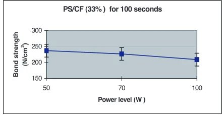
material [PS/CF (33%)] was weakened by the excessive exposure to microwave irradiation. Figure 11 shows the lap shear strength of PS/CF (33%) versus different power levels at an exposure time of 100 seconds. The laps shear strength reducers from 237 N/cm2 at an exposure time of 50 seconds to 209 N/cm2 at an exposure time of 100 seconds. The failures were at parent material hence in all cases the parent material was weakened by excessive exposure to microwave energy. The excessive absorption of microwave irradiation was due to primarily the presence of carbon fibers which could be coupled to microwaves efficiently [22].
PS/CF(33% ) at 100W
0 100 200 300 400
60 80 100 120
Exposure time (s)
Bond strength
(N/cm
2)
Figure 10. Lap shear strength of PS/CF (33%) bonds joined by VMF.
PS/CF (33% ) for 100 seconds
150 200 250 300
50 70 100
Power level (W )
Bond strength
(N/cm
2)
Figure 11. Lap shear strengths of PS/CF (33%) joined by VFMF at different power levels.
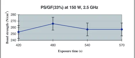
370 N/cm2 respectively. The quality of the bonds was not good. The failures were at the parent material. This means that the parent material [PS/GF (33%)] is weakened by the excessive exposure to microwave irradiation. At an exposure time of 420 seconds, the peak lap shear strength is 430 N/cm2, which is 55% higher than the average lap shear bond strength obtained by curing the Araldite under ambient conditions. For all intervals of exposure to VFM, the lap shear strengths are stronger than the average lap shear strength procured under ambient environment.
PS/GF (33%) at 200 W
300 350 400 450 500
180 240 300 420 450 480
Exposure Time (s)
Bond Strength (N/cm
2)
Figure 12. Lap shear strengths of PS/GF (33%) bonds joined by VFMF.
With VFM facility with a power of 200 W and Araldite as primer, no bond was formed if the processing time was less than 150 seconds. Bonds started to form at an exposure time of 180 seconds. At an exposure time of 450 seconds or over, the parent material was weakened because when it was subjected to lap shear test, failure occurred at the parent material.
Case 4
increased with increasing central frequency. This was expected as earlier researchers found that the loss tangent of BCB increased with frequency in the range of 2.4to 8.1 GHz [25, 26].
Fourier transform infrared (FTIR) spectroscopy analysis showed that the spectra of VFM cure and thermally cured films were essentially identical with no significant differences. These implied that the chemical structure of VFM cured films was similar to conventionally cured films. To determine the effectiveness of VFM processing, BCB films were cured for 30 minutes at 175, 200 and 225◦C, in a VFMF, in a conventional thermal furnace, and on a hot plate. All samples were ramped at 30◦C per minute. For each cure condition, a comparable or higher conversion was achieved by VFM processing. BCB films were cured for different times at final cure temperatures ranging from 175 to 250◦C. Samples were processed at a central frequency of 6.425 GHz with full bandwidth of 1.15 GHz and a sweep time of 0.1 second. All samples were ramped at 30◦C per minute. The extent of cure increased with both temperature and cure time. At any given temperature, the rate of reaction levelled off, this suggests vitrification of the polymer matrix. This phenomenon is commonly found in thermally cured thermosetting polymer systems [25].
The optical and electrical properties of VFM-cured films were characterized and compared to thermally cured films. BCB samples were cured by a VFMF, a thermal furnace and a hot plate under similar conditions. The index of refraction decreased from 1.59 to 1.55 for a fully cured sample. At each of these conditions, the VFM cured samples showed comparable or lower indices of refraction than the thermally cured films. This was consistent with the higher extent of cure attained in theses samples compared to the thermally cured samples. The dielectric constant decreased with increasing extent of cure, and VFM cured films showed a comparable dielectric constant to thermally cured films for all the cure conditions. The dielectric constant of VFM processes, fully cured BCB film was 2.68 and its loss tangent was 0.0011 [25].
high conversions. However, VFM cured films showed very low stress until about 70% conversion and, thereafter, a final residual stress close to that of the thermally cured ones. The activation energy, Ea for
the cure reaction by VFM processing was found to be 25 kcal/mol, which was about 30% lower than that of the thermally cured one. This means VFM enhances reaction kinetics. A 10 minute VFM processing at 250◦C gave the same conversion as the control full cured sample. At his temperature, for conventional thermal curing, vitrification is known to occur in about 5 minutes, giving a conversion of about 90%, and in the next 55 minutes, the reaction advances to only about 95%. Microwave processing, thus shows a significant improvement in the post-vitrification reaction rates. As a result of higher reaction rates, the reaction proceeds farther to completion before vitrification for microwave curing as compared with thermal processing [25].
Comments on cases
PS/GF (33%) at 400 W, 2.45 GHz
100 150 200 250 300 350 400
50 100 150 200 250 300
Exposure time (s)
Bond strength (N/cm
2)
Figure 13. Lapshear strengths of PS/GF (33%) joined by fixed frequency microwave (2.45 GHz) of 400 W in a slotted rectangular waveguide using rapid Araldite.
PS/GF(33%) at 150 W, 2.5 GHz
240 250 260 270 280
420 480 540 570
Exposure time (s)
Bond strength (N/cm
2)
Figure 14. Lap shear strengths of PS/GF (33%) using VFM facility with primer and at 2.5 GHz.
6. CONCLUSION
In general, variable frequency microwave processing of materials is superior to its fixed frequency rival. On the other hand, the fixed frequency facilities are much cheaper than its counterpart at this point in time. However, this is likely to change in the coming ten years. Whether it is fixed or variable frequency of microwave processing, the curing time for composites has been largely reduced with the enhanced or comparable materials properties. In addition, the glass transition temperature (Tg) for all composites shifted to a higher temperature
REFERENCES
1. National Research Centre (NRC), Microwave Processing of Materials, 1–7, 11–12, 100, 105, National Materials Advisory Board, Commission on Engineering and Technical Systems, National Academy Press, USA, 1994.
2. Venkatesh, M. S. and G. S. V. Raghavan, “An overview of microwave processing and dielectric properties of agri-food materials,” Biosystems Engineering, Vol. 88, No. 1, 1–18, 2004. 3. Thostenson, E. T. and T. W. Chou, “Microwave processing:
Fundamentals and applications,” Composites A, Vol. 30, 1055– 1071, 1999.
4. Ku, H. S., E. Siores, and J. Ball, “Productivity improvement through the use of industrial microwave technologies,” Journal of Computers and Industrial Engineering, Vol. 42/2-4, 281–290, 2002.
5. Lee, W. I. and G. S. Springer, “Microwave curing of composites,”
Journal of Composite Materials, Vol. 18, 387–409, 1984.
6. Metaxas, A. C. and R. J. Meredith,Industrial Microwave Heating, 5–6, 28–31, 43, 211, 217, 278, 284–285, Peter Peregrinus Ltd., 1983.
7. Liu, F., I. Turner, E. Siores, and P. Groombridge, “A numerical and experimental investigation of the microwave heating of polymer materials inside a ridge waveguide,” Journal of Microwave Power and Electromagnetic Energy, Vol. 31, No. 2, 71–82, 1996.
8. Wei, J. B., K. Ngo, D. A. Tucker, Z. Fathi, F. L. Paulauskas, and W. G. Johanson, “Industrial processing via variable frequency microwaves part I: Bonding applications,” Journal of Microwave Power and Electromagnetic Energy, Vol. 33, No. 1, 10–17, 1998. 9. Everleigh, C. A., A. C. Johnson, R. J. Espinosa, and
R. S. Garard, “Use of high power travelling wave tubes as a microwave heating source,”Material Research Society Symposium Proceeding, Vol. 347, 79–89, 1994.
10. Fathi, Z., R. S. Garard, M. T. DeMeuse, J. Clemens, and C. Saltiel, “Processing and modelling of select PMCs using variable frequency microwave irradiation,” Polym. Mater. Sci. Eng., Vol. 72, 74–75, 1995.
12. Ku, H. S., E. Siores, and J. A. R. Ball, “Welding of thermoplastic composite using microwave energy,” Proceedings of CIRP International Symposium — Advanced Design and Manufacturing in the Global Manufacturing Era, Vol. 2, 612-8, Hong Kong, August 21–22, 1997.
13. Bolton, W., Materials and Their Uses, 128, Butterworth and Heinemann, 1996.
14. Ku, H. S., V. Puttgunta, and M. Trada, “Young’s modulus of vinyl ester composites cured by microwave irradiation: Preliminary results,” J. of Electromagn. Waves and Appl., Vol. 20, No. 14, 1911–1924, 2006.
15. Ku, H. S., M. Trada, V. Puttgunta, and V. Kota, “Yield and tensile strength of vinyl ester composites cured by microwave,”J. of Electromagn. Waves and Appl., Vol. 21, No. 4, 517–526, 2007. 16. Cardona, F., H. S. Ku, N. Pattarachaiyakoop, D. Rogers, and
M. Trada, “Fracture toughness of phenol formaldehyde composites post-cured in microwave,” J. of Electromagn. Waves and Appl., Vol. 21, No. 14, 2137–2146, 2007.
17. Schwartz, M. M., Composite Materials Handbook, 2nd edition, 6.55-56, McGraw-Hill, USA, 1992.
18. Varadan, V. K. and V. V. Varadan, “Microwave joining and repair of composite materials,”Polymer Engineering and Science, Vol. 3, No. 7, 470–486, 1991.
19. Schwartz, M. M., Joining of Composite-matrix Materials, 64 , ASM International, USA, 1995.
20. Ku, H. S., E. Siores, and J. A. R. Ball, “Relationship between microwave irradiation and constituents of composites during joining process,” Transactions, Vol. 7, No. 3, 41–49, The Hong Kong Institution of Engineers, 2000.
21. Ku, H. S., E. Siores, J. A. R. Ball, and M. MacRobert, “Variable frequency microwave processing of thermoplastic composites,”
Plastics, Rubber and Composites, Vol. 29, No. 8, 278–284, 2000. 22. Liu, Y., Y. Xiao, A. Sun, and D. A. Scola, “Microwave irradiation
of nadic-end-capped polyimide resin (RP-46 resin) and glass-graphite-RP-46 composites: Cure and process study,”Journal of Applied Polymer Science, Vol. 73, 2391–2411, 1999.
24. Ku, H. S., E. Siores, J. A. R. Ball, and M. MacRobert, “Char-acterization of thermoplastic composites using variable microwave facilities configuration,”Plastics, Rubber and Composites, Vol. 29, No. 8, 285–287, 2000.
25. Tanikella, R. V., S. A. B. Allen, and P. A. Kohl, “Variable frequency microwave curing of Benzocyclobutene,” Journal of Applied Polymer Science, Vol. 83, 3055–3067, 2002.
26. Lauren, K, et al., Multi-Chip Module Conference Proceedings, IEEE, 229–231, 1995.
27. Liu, H.-X., H. Zhai, L. Li, and C.-H. Liang, “A progressive numerical method combined with MON for a fast analysis of large waveguide slot antenna array,” J. of Electromagn. Waves and Appl., Vol. 20, No. 2, 183–192, 2006.
28. Yau, D. and N. V. Shuley, “Numerical analysis of coupling between dielectric image guide and microstrip,”J. of Electromagn. Waves and Appl., Vol. 20, No. 15, 2215–2230, 2006.
29. Habashy, T. M. and A. Abubakar, “A generalized material averaging formulation for modelling of the electromagnetic fields,”
J. of Electromagn. Waves and Appl., Vol. 21, No. 9, 1145–1159, 2007.
30. Engstr¨om, C. and D. Sj¨oberg, “On two numerical methods for homogenization of Maxwell’s equations,” J. of Electromagn. Waves and Appl., Vol. 21, No. 13, 1845–1856, 2007.
31. Hatamzadeh-Varmazyar, S. and M. Naser-Moghadasi, “New numerical method for determining the scattered electromagnetic fields from thin wire,” Progress In Electromagnetics Research B, Vol. 3, 207–218, 2008.
32. Suyama, T., Y. Okuno, A. Matsushima, and M. Ohtsu, “A numer-ical analysis of stop band characteristics by multilayered dielectric gratings with sinusoidal profile,”Progress In Electromagnetics Re-search B, Vol. 2, 83–102, 2008.
![Figure 1. Most applicators are multimode, where a lot of field patternsare excited simultaneously [1].](https://thumb-us.123doks.com/thumbv2/123dok_us/1906835.1249814/3.612.164.363.203.330/figure-applicators-multimode-lot-eld-patternsare-excited-simultaneously.webp)