Available online: https://pen2print.org/index.php/ijr/ P a g e | 624
Design and Analysis of G+10 Building From Indian Code
Archanatripathi
M.Tech Student
Department of Civil
Gyan Ganga Institute of Technology and Science
Jabalpur, Madhyapradesh, India.
ABSTRACT
This exam concentrates on relationship of International measures. The picked benchmarks Indian code i.e. IS 1893:2002. The investigation in like way energizes in understanding the govern contributing included substances which impel poor execution of Structure amidst the shake, while in travel to accomplish their pleasing secure lead underneath destiny seismic tremors. The shape isolated is symmetrical, G+10, Special RC Moment Resisting Frame (SMRF). Appearing of the structure is finished by staad Pro V8i programming. The Lateral seismic powers are found out physically. The Lateral seismic powers are figured by ground unsurprising with different codes in X and Z bearing and are related with the Center of gravity of the shape. The illustrative consequences of the variation structures are then tended to graphically and alive and well, it's miles taken a gander at and isolated looking any essential separations. This examination concentrates on investigating sorts inside the outcomes got using the three Indian code. A close research is done the extent that Base shear, Displacement, Axial load, Moments in Y and Z heading for picked parcels what's more separating Displacement, Axial load, Moments in Y and Z bearing Floor able of different codes for same picked portions. Joined through relative research of Displacement, shear Y, Torsion and Moment Z of picked sections on each floor for various general codes.
Watchwords: Indian code IS 1893:2002 and SMRF.
1.1 INTRODUCTION
Ordinary disasters which join shakes, Tsunamis, Landslides, Floods et cetera. Makes genuine damage and persisting individual by strategies for falling many structures, finding or killing individuals, cutting off conveyance systems, deterring of course structures, animals dangers and so on. Such calamitous occasions are massive asking for conditions to the progress of progress. Nevertheless, basic engineers play a principle position in restricting the damages by using right arranging the systems or by right material choices or right structures way and taking other profitable judgments. This includes taking in the shudders, lead of the substances of age and structures and the sum to which essential pros make usage of the data in taking proper choices in arranging the systems made of upheld bond. Seismic tremors are portrayed as a vibration of the world's floor that happens after a landing of value inside the world's outside. Since the world's outside layer is included different plates which can be continually moving step by step, vibrations can rise which accomplish little shakes. Most seismic tremors are close to nothing yet aren't easily felt. Greater and fierce seismic tremors are those which occur ina dispatch of imperativeness as the plates slide past or collide
with each other. The qualities involving significance, length, and so on. Of seismic floor vibrations expected at any range depend on the extent of tremor, its energy of care, expel from the epicenter, characteristics of the course through which the seismic waves visit, and the soil strata on which the structure stands. Approach the arrangement in an extra learned, loathe following a black box; and Appreciate and change the adjustments in code courses of action better and speedier. The general objective is with the objective to configuration sustained strong structures which can be:
1. Safe
2. Economical
3. Efficient
Reinforced concrete is one of the fundamental creating substances utilized as a part of manufactured structures due to the truth:
1. Low cost
2. Weathering and fireplace insurance
Available online: https://pen2print.org/index.php/ijr/ P a g e | 625
4. Formability
Each one of these models make concrete a charming surface for monstrous extent of essential packages close by structures, dams, supplies, tanks, and so forth.
OBJECTIVE OF THE PROJECT
The first target of this undertaking is to pass on out the basic contributing parts which cause dreadful general execution for the length of the tremor and make pointers which must be considered in plotting the multistoried strengthened strong homes with the objective that you can get their adequate secure direct under destiny seismic tremors. Seismic tremor codes were changed and revived depending at the updates inside the depiction of floor developments, soils and structures. The Indian Standard Code IS: 1893 pushed toward winding up undeniably dynamic in 2002 that empowers you to deal with the different framework issues displayed out inside the seismic tremor lead of the RC Buildings. The picked necessities are Indian Standard Code IS: 1893.A relative examination changed into completed the process of in regards to Base shear, Displacement, Axial load, Moments in Y and Z course for picked segments and furthermore evaluating Displacement, Axial load, Moments in Y and Z course Floor sharp of different codes for level with settled on sections. Joined by technique for close evaluation of Displacement, shear Y, Torsion and Moment Z of picked bars on each ground for one of kind codes.
CODES AND ITS SPECIFICATIONS
Structures should be arranged and created as per the courses of action of a development law, that is a legitimate report containing necessities related with things like assistant prosperity, fireplace security, funnels, ventilation, and accessibility to the physically disabled. codes are created through various altruistic social occasions in a shape that is effectively taken after by methods for Indian Standard Code IS: 1893, A comparable examination changed into completed in articulations of Base shear, Displacement, Axial load, Moments in Y and Z course for picked segments and moreover taking a gander at Displacement, Axial load, Moments in Y and Z way Floor clever of different codes for same settled on portions. Ran with by methods for close appraisal of Displacement, shear Y, Torsion and Moment Z of picked shafts on each ground for
prohibitive codes. Locale stays for American Railway Engineers Association; This is guide of railroad building.
Weights
- Forces for which a structure ought to be proportioned. Weights that follow up on shape can be parceled into three groupings.
Dead Loads
Dead loads are the ones which are unsurprising in essentialness and settled in range at some stage in the lifetime of the structure together with: ground fill, end ground, and put rooftop for homes and passing on surface, walkways, and reducing for ranges.
Live Loads
Live hundreds are the ones which are either totally or deficiently in territory or not favoring by any extend of the creative energy, may trade region; the unimportant stay masses for which the ground surface and best of a building must be formed are frequently laid out in development law that speaks to at the page of age (see Table 1 - "Slightest Design Loads for Buildings and Other Structure.")
SERVICEABILITY
Serviceability requires that
1Deflections be capability little;
2.Cracks if any be put away to a decent points of confinement;
3.Vibrations be limited.
Wellbeing
A structure should be protected against fall; power of the shape should be alright for each of the hundreds that may follow up on it. In the event that we should construct homes as outlined, and if the majority and their internal impacts can be expected as it ought to be, we do now not must dread around assurance. Be that as it may, there are vulnerabilities in:
Available online: https://pen2print.org/index.php/ijr/ P a g e | 626
2.Forces/masses is most likely administered in a way particular from what we accepted;
3.The suppositions in assessment won't be absolutely right;
4.Actual conduct is likely selective from that accepted; and numerous others.
At long last, we might truly want to have the structure safe towards weak disappointment (continuous disappointment with adequate cautioning allowing healing measures is most well known to an amazing or fragile disappointment). Tremor or seismic execution characterizes a shape's capability to save its critical abilities, such help security and serviceability, at and after a particular quake introduction. A structure is usually viewed as sheltered on the off chance that it does now not jeopardize the lives and pleasantly being of these in or round it by utilizing incompletely or totally falling. A shape might be mulled over serviceable on the off chance that it could satisfy its operational highlights for which it transformed into outlined. Fundamental thoughts of the quake building, actualized inside the basic developing codes, accept that a building should live to tell the story a remarkable, exceptionally extraordinary seismic tremor through supporting significant mischief however without all inclusive crumbling. On the inverse hand, it need to keep on being operational for more prominent regular, however less serious seismic exercises.
2.LITERATURE REVIEW
SERGIO HAMPSHIRE DE C. SANTOS et al
This paper presents a comparative evaluation among
some international, European and American, seismic
design standards. A model for a standard reinforced concrete building (“Model Building”) has been
developed to permit the comparison among codes. This
building has been modelled with two different computer
programs, SAP2000 and SOFiSTiK and subjected to
seismic input according to the several seismic codes. The
obtained results compared are leading to some important
conclusions
Jaime Landingin et al The present paper presents a
comparison of seismic provisions of three seismic design
codes, the Philippine code, Eurocode 8 and the American
code, to the most common ordinary residential frames of
standard occupancy. Regular and irregular reinforced
concrete frames were analyzed and compared for four
storey building types. The response spectrum and the
seismic parameters of NSCP 2010 were considered for
the horizontal load action with different load. Therefore,
the RC buildings designed using the EC8 are expected to
have larger reinforcement requirements than the
buildings designed using the NSCP 2010 and 2009 IBC.
3.METHODOLOGY
The method labored out to gain the noted objectives is as follows:
1. Modeling of the selected building in Staad seasoned. V8i Software.
2. Retrieved term of shape from the software program.
3. Three fashions as per the codes i.E. Indian code, specification have been made.
4. Applied manually calculated Lateral seismic forces and load mixtures as in line with IS 1893-2002.
5. analysed the models and graphical and tabular representation of the data is presented.
TIME PERIOD
The equal static methods undertake seismic coefficient, which depends at the herbal term of their vibration of the structure, the term is needed for earthquake resistance design of the structures and to calculate the base shear. Time period of the structure is been taken from the software Staad pro. Time length in sec:
Available online: https://pen2print.org/index.php/ijr/ P a g e | 627
For Z direction: 1.005
These values of time period of the shape is taken and the bottom shear for Indian code, is calculated respectively in both X and Z course.
DISTRIBUTION OF THE HORIZONTAL SEISMIC FORCES
Different load calculation and base shear calculation method has been adopted for distinct codes as designated inside the respective codes. I.E. IS 1893-2002, the base shear is calculated and is shipped alongside the height of the building at every ground. The lateral seismic pressure (kN) brought on at any stage is decided as exact within the codes.
INDIAN STANDARDS IS-1893:2002
IS 1893:2002 is denoted as “Criteria for earthquake resistant Design of structures” Part 1 General provisions and buildings. Vertical Distribution of Base Shear to Different Floor Levels is said in IS 1893:2002.The design lateral pressure shall first be computed for the constructing as an entire. The design lateral force shall then be allotted to the various ground stages. This ordinary layout seismic pressure for this reason obtained at each floor stage shall then be disbursed to individual lateral load resisting elements depending at the floor diaphragm action. The design base shear calculated will be disbursed
alongside the height of the constructing as in line with the subsequent expression
4. DESIGN CALCULATIONS
Specifications: The specifications used in
modeling are
Table-1.3: Specifications used in modeling
Sr. No
Parameters Dimensions/Type
1 Plan dimension 27 x 17 m
2 Number of stories G+10
3 Total height of building
36m
4 Height of each storey
3m
5 Column size 600 X 350 mm
6 Beam size 500 x 300 mm
7 Grade of concrete M20
8 Frame type SMRF
9 Soil type Medium soil
10 Live load 2.5 KN/m
11 Inner wall 150 mm
12 Outer wall 250 mm
13 Slab thickness 150mm
14 Unit weights of Concrete
25 KN/Cum
15 Unit weights of brick work
19KN/Cum
Available online: https://pen2print.org/index.php/ijr/ P a g e | 628 • Strength Design Method
• Working Stress Design
• Limit State Design
REQUIRED STRENGTH (FACTORED
LOAD) U
To resist dead load & live load:
U=1.4DL + 1.7LL
If resistance to structural effects of specific wind load
U= 0.75(1.4DL+1.7LL+1.7W)
U=0.9DL+1.3W not less than 1.4DL+1.7LL
If resistance to specified earthquake loads
U= 0.75(1.4DL+1.7LL+1.87E)
U=0.9DL+1.43E not less than 1.4DL+1.7LL
If resistance to specified earth pressure
U= 1.4DL+1.7LL+1.7H
U=0.9DL not less than 1.4DL+1.7LL
Where structural effects T of differential settlement, creep, shrinkage or temperature change are significant.
U= 0.75(1.4DL+1.4T+1.7LL) not less than 1.4(DL+T)
5. RCC DESIGN FOR STRUCTURE
STAAD.PRO
STAAD.Pro is an analysis and design software package deal for structural engineering. This guide is meant to manual users who're new to this software program in addition to experienced users who need precise records on the basics of the usage of this system.
STAAD or (STAAD. Pro) is a structural analysis and design computer software originally evolved by means of Research Engineers International at
Yorba Linda, CA in 1997. In past due 2005, Research Engineers International turned into offered with the aid of Bentley Systems. An older model referred to as Staad-III for Windows is utilized by Iowa State University for educational purposes for civil and structural engineers.
It supports several metallic, concrete and wood design codes. It can make use of diverse types of analysis from the conventional 1st order static evaluation, 2nd order p-delta analysis, geometric non-linear evaluation, Pushover analysis (Static-Non Linear Analysis) or a buckling evaluation. It can also make use of various types of dynamic analysis from modal extraction to time records and response spectrum evaluation.
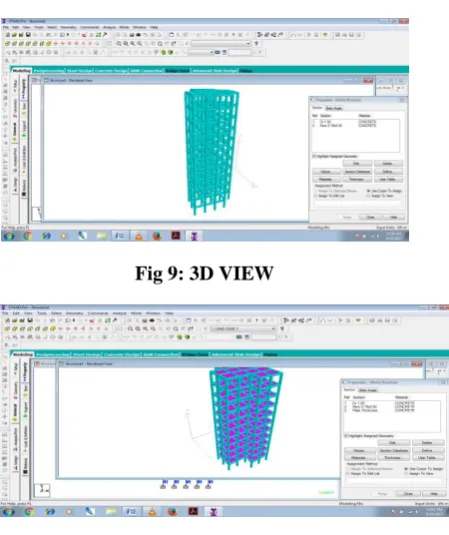
3D VIEW OF THE SELECTED BUILDING
Fig 9: 3D VIEW
Fig 10: Slab thickness 150mm
Available online: https://pen2print.org/index.php/ijr/ P a g e | 629
Fig-12: Selected Column
Fig-14: Selected Beam in X Direction
Fig-15: Selected Beam in Z Direction
6.ANALYSIS AND RESULTS
OVERVIEW
A G+10 building is analyzed with Indian code specifications during the earthquake. Parameters like base shear, displacement, axial force, bending moments, for column is calculated and shear, moment, displacement and torsion for beam is calculated. Graphical and Tabular representation of data is discussed in this chapter.
BASE SHEAR
In X Direction
Table-1: Base shear for earthquake in X-direction
Different Codes Base Shear in X direction (KN)
India Code 2187.4046
Fig-6.2.1: Base Shear for earthquake in X-direction
In Z Direction
Table-2: Base shear for earthquake in Z-direction
Different Codes
Base Shear in Z direction (KN)
Indian Code 1645.4506
COLUMN
Maximum Displacement on each column
Table-3: Maximum Displacement on each column
Name of column
Maximum Displacement on each column
INDIAN CODE(mm)
C1 62.855
C2 62.895
C3 62.885
C4 63.164
C5 62.935
C6 63.249
C7 62.822
C8 62.935
C9 62.858
Available online: https://pen2print.org/index.php/ijr/ P a g e | 630
Displacement
6.3.3 Maximum Axial Force on each column
Table-4: Maximum Axial Force on each column
Name of column Maximum Axial Force on
each column INDIAN CODE(KN)
C1 2572.874
C2 2885.308
C3 2416.511
C4 2856.556
C5 2548.002
C6 2991.436
C7 2338.237
C8 2548.002
Maximum axial force (KN)
Table-5: Maximum Axial force
Different Codes Maximum axial force (KN)
INDIAN CODE 2991.436
Maximum Moment-Y on each column
Table-6: Maximum Moment-Y on each column
Name of column Maximum Moment-Y on
each column INDIAN CODE(mm)
C1 92.78
C2 98.495
C3 95.943
C4 91.985
C5 98.976
C6 97.621
C7 93.169
C8 98.976
C9 128.19
Maximum
Moment-Y 128.19
Maximum Moment-Z on each column
Table-7: Maximum Moment-Z on each column
No. of column INDIAN CODE(mm)
Moment at Z
C1 140.65
C2 136.266
C3 155.577
C4 153.517
C5 155.732
C6 154.849
C7 140.56
C8 155.732
C9 148.353
Maximum
Moment-Z 155.732
FLOOR WISH COMPARISON Maximum Displacement on each Floor
Table-8: Maximum Displacement on each Floor
Height(M) Indian(mm)
Available online: https://pen2print.org/index.php/ijr/ P a g e | 631
0 0
3 4.234
6 10.245
9 16.534
12 22.91
15 29.269
18 35.504
21 41.492
24 47.095
27 52.164
30 56.532
33 60.02
36 62.477
Maximum Axial force on each floor
Table-9: Maximum Axial force on each floor
Height(M) Indian(mm)
Axial Force
0 2736.804
3 2483.952
6 2234.962
9 1989.298
12 1746.376
15 1505.722
18 1266.911
21 1029.564
24 793.324
27 557.881
30 323.343
33 103.56
Maximum Moment-Y on each Floor
Table-10: Maximum Moment-Y on each floor
Height(M)
Indian(KN)
Moment at Y
0 92.587
3 108.18
6 106.99
9 105.563
12 101.99
15 96.617
18 89.532
21 80.802
24 70.484
27 58.63
30 55.723
33 53.796
Maximum Moment-Z on each Floor
Table-11: Maximum Moment-Z on each floor
Height(M) Indian(KN)
0 135.365
3 126.275
6 122.048
Available online: https://pen2print.org/index.php/ijr/ P a g e | 632
12 119.673
15 114.601
18 107.37
21 98.093
24 86.763
27 73.88
30 59.728
33 55.926
BEAM
Maximum Displacement on beam at each floor
Table-12: Maximum Displacement on beam at
each floor
Floors INDIAN CODE
Displacement
GF 4.406
3RD 8.578
6TH 11.534
9TH 13.05
11TH 12.139
Maximum
Displacement
(mm)
13.05
Maximum Moment-Z KNm on beam at each floor
Table-13: Maximum Moment-Z on beam at each
floor
Floors INDIAN CODE
Moment at Z(kNm)
GF 183.201
3RD 203.169
6TH 192.894
9TH 161.726
11TH 83.852
Maximum
Moment-Z
(kNm)
203.169
Maximum Shear-Y KN on beam at each floor
Table-14: Maximum Shear-Y on beam at each floor
Floors INDIAN CODE
Moment at Z(KNm)
GF 149.047
3RD 169.065
6TH 158.218
9TH 124.889
11TH 61.665
Maximum
Moment-Z
(kNm) 169.065
Maximum Torsion kNm on beam at each floor
Table-15: Maximum Torsion on beam at each floor
Floors
INDIAN CODE(KNm)
Torsion
GF 21.599
3RD 24.802
6TH 20.983
9TH 12.686
11TH 5.684
Maximum
Available online: https://pen2print.org/index.php/ijr/ P a g e | 633
7.CONCLUSIONS
1. BASE SHEAR AS PER INDIAN CODES.
1.Calculated Base shear in X course 2.Calculated Base shear in Z course
2. Movement, AXIAL LOAD, MOMENT FOR SELECTED COLUMNS.
1.Displacement as per Indian code is most conversely with different codes,
2.Axial power as concerning Indian code is most when appeared differently in relation to various codes.
3.Moment-Y as concerning Indian code is most appeared differently in relation to various codes.
4.Moment-Z as ahead of time with Indian code is most conversely with different codes.
3. Evacuation, MOMENT-Z, SHEAR-Y AND TORSION FOR SELECTED BEAMS
1.Displacement as unsurprising with Indian code is most noteworthy when diverged from various codes.
2.Moment-Z as per Indian code is most stood out from various codes.
3.Shear-Y as concerning Indian code is most extraordinary when appeared differently in relation to different codes.
8.REFERENCES
[1] Dr. S.V. Itti, Prof. Abhishek Pat hade and Ramesh B. Karadi, "A Comparative Study on Seismic Provisions Made in Indian and International Building Codes for RC Buildings".
[2] Md. S. Bari • T. Das (2013), "A Comparative Study on Seismic Analysis of Bangladesh National Building Code (BNBC) with Other Building Codes", J. Inst. Eng. India Ser. An (August– October 2013) 94(3):131– 137.
[3] Jaime Landingin, Hugo Rodrigues, Humberto Varum, António Arêde (2013),"Comparative Analysis of RC Irregular Buildings Designed According to Different Seismic Design Codes", The Open Construction and Building Technology Journal, 2013, Volume 7:221-229.
[4] M. Araujo, J. M. Castro, X. Romao and R. Delgado (2012), "Relative Study of the European and American Seismic Safety Assessment Procedures for Existing Steel Buildings"
[5] Ioannis P. Giannopoulos (2009), "Seismic Assessment of a RC Building with respect to FEMA 356 and Eurocode 8", 16ο Συνέδριο Σκυροδέματος, Τεε, Ετεκ, 21-23/10/2009, Πάφος, Κύπρος.
[6] Balthasar Novák, K. Ramanjaneyulu, Constanze Roehm and Saptarshi Sasmal, "Relationship of Seismic Performance of D-locale of Existing RC Structures Designed with Different Recommendations".
[7] Sergio hampshire de c. santos , luca zanaica ,
carmen bucur, silvio de souza lima , ana
arai[2013]Vol. 9-No. 1-2013,“comparative study of
codes for seismic design of structures”.
[8] Jaime landingin, hugo rodrigue, humberto
varum, antónio arêde and aníbal
cost[2013]Department Of Civil Engineering,
University Of Aveiro, Portugal, Department Of
Civil Engineering, University Of Porto, Portugal.
The Open Construction And Building Technology
Journal, 2013, 7, 221-229. “Comparative Analysis
Of RC Irregular Buildings Designed According To different Seismic Design Codes”.
Author’s Profile