A Bit-Plane Decomposition Row-Based Pipo Vlsi
Architecture For Hevc
Vagu. Radha Haneesha & Vemu. Srinivasa Rao
1M.tech-Scholar, Dept of ECE, Shri Vishnu Engineering College of Women, Vishnupur, West Godavari District, Bhimavaram, A.P, India
2Associate Professor, Dept of ECE, Shri Vishnu Engineering College of Women, Vishnupur, West Godavari District, Bhimavaram, A.P, India
ABSTRACT: High Efficiency Video Coding
(HEVC) is currently being prepares as the modern video coding standard of the video coding Experts Group and the International Standard Organization / International Electrotechnical Commission (ISO/IEC) Moving Picture Experts Group. VLSI Architecture is proposed for the HEVC encoder. The VLSI architecture is based on signed bit transform (SBT) matrix which contains only 0,1 or -1. These SBT matrices are very simple and have lower bit width and reduce number of addition operations because it contains many zero elements. So here adder reuse strategy can be used. Hence power consumption and area consumption are reduced. So the VLSI architecture can be synthesised with proper area and high speed. The proposed transform hardware architecture can process video data with higher speed and reduced area.
Keywords: High Efficiency Video Coding, Signed Bit Tansform, High Efficiency Video Coding.
I. INTRODUCTION
Recently, the High Efficiency Video Coding (HEVC) standard is the joint video project of Video Coding Experts Group (VCEG) and the International Organization for Standardization/ International Electrotechnical Commission (ISO/IEC) Moving Picture Experts Group (MPEG) standardization organizations which are working together in a partnership known as the Joint Collaborative Team on Video Coding (JCT-VC). HEVC is the latest video coding with a higher coding performance than other existing ones. Many novel coding algorithms are introduced in HEVC.
The 32 × 32 transform is the most complex in the transforms of HEVC; thus, the improvement of the 32 × 32 transform also can be efficient for the whole transform circuit.
Applying the proposed SBT algorithm to the transform architecture, instead of the integer transform matrix circuits, the SBT matrix circuits are implemented and the input data are transformed with each SBT matrix circuit, respectively. Due to the simple elements of SBT matrices, the bit widths of intermediate transformed data and output data are significantly reduced. The bit widths of SBT increase slowly as the intermediate data are processed stage by stage, which shortens the circuit delay and constrains the clock cycle to be smaller. Additionally there are so many zero elements in SBT matrices. The sparse characteristic of the SBT matrices can benefit for reducing the addition operations in the transform process. Thus, the adders reuse method based on the element redundancy characteristic of SBT matrices for reducing the number of adders.
Many research works on transform implementation optimization for HEVC have been done in the past. Meher et al.
structure and multiplier less implementation, were adopted for saving the hardware cost. The work presented a transform architecture that uses the canonical signed digit representation and common sub-expression elimination technique to perform the multiplication with a shift-add operation. Based on these optimizations, the transform architecture is greatly simplified for practice application. However, with the increasing applications of high definition (HD) and ultra HD video coding, the higher processing capacity of codes is required. Thus, all modules in video code, including the transform, need to be further improved for real-time coding with low complexity.
The existing transform architectures consider how to reduce the number of arithmetic operators, such as addition and multiplication, more than the data bit width in the transform. In fact, the data bit width is also an important factor impacting on the circuit speed and area of VLSI architecture.
A circuit with a large bit width needs a larger number of fan-in or fanout of logic gate, and more MOS devices are required in the logic gate circuit. Thus, the capacitive load and resistance of the logic gate all increase with widening bit width. According the first-order resistance and capacitance (RC) circuit model theory, the delay of the circuit is related with RC. Large RC leads to long circuit delay. The circuit delay varying with the increasing input bit width in two typical CMOS processes. As for the adder, the carry chain is the critical path for the circuit delay, which is also dependent on the input and output bit width.
Each extra bit increasing will lead to larger delay. Thus, aside from the number of
other optimization factor for fast transform architecture. In this brief, we propose a new VLSI architecture for the integer transforms of the HEVC standard for reducing the bit widths of data. The integer transform matrix is decomposed into several signed bit-plane transform (SBT) matrices that are used in the proposed architecture. Moreover, a number of adders are reused based on the redundant property of elements of bit matrices. With the bit matrix-based transform algorithm, the proposed VLSI transform architecture can process 32 pixels/cycle data throughput maximally with very high working frequency and proper area.
II. EXISTED SYSTEM
In order to narrow the bit width of intermediate transformed data, the bit decomposition algorithm decomposed the integer transform matrix into several SBT matrices.
Let di,j be the element in the ith row and jth
column in the N × N integer transform matrix DN, i.e., DN = (di,j). If di,j is positive,
the binary expression of di,j is (bK−1,i,j, . . . ,
b1,i,j, b0,i,j)2, bk,i,j ∈ {0, 1}. Then, there is the
relation
di,j = ∑𝑘−1𝑘=0(𝑠𝑔𝑛(di,j) bk,i,j 2k), bk,i,j∈{ 0, 1}
where K is the number of binary significant bits of element di,j , bk,i,j denotes
the kth bit of di,j, and sgn(*) is the sign
indication function that returns 1 for the positive value and −1 for the negative value. Thus above equation can also be rewritten as
di,j = ∑𝑘−1𝑘=0( bk,i,j 2k) , bk,i,j∈{ 0, sgn(di,j)}
Fig 1. Hierarchical structure of signed bit transform (SBT)
Applying the signed bit transform (SBT) algorithm to the transform architecture, instead of the integer transform matrix circuits, the SBT matrix circuits are implemented and the input data are transformed with each SBT matrix circuit, respectively. Due to the simple elements of SBT matrices, the bit widths of intermediate transformed data and output data are significantly reduced.
Taking the 32 × 32 1-D integer transform as an example, the increasing bit width of output data is only 5 b with the SBT algorithm, compared with the 11-b increasing of the straightforward integer transform. The bit widths of SBT increase slowly as the intermediate data are processed stage by stage, which shortens the circuit delay and constrains the clock cycle to be smaller. Although the delay of the integer transform circuit is reduced based on the bit transform algorithm, more adders are required due to more SBTs.
However, the bit widths of adders used in SBT are also so low that the addition operation is also very fast. Additionally, It can be observed that many zero elements are in the SBT matrix. The number of actually required addition operations is seldom due to the sparse SBT matrix according to the rule of matrix multiplication. The sparse characteristic of the SBT matrices can benefit for reducing the addition operations in the transform process.
III. PROPOSED SYSTEM
In signal processing data compression, source coding, or bit-rate reduction involves encoding information by utilizing fewer bits than the original representation. Compression can be either lossy or lossless. Lossless compression reduces bits by identifying and eliminating statistical redundancy. In lossless compression, there is no loss of information. Lossy compression reduces bits by removing unnecessary or less important information. The process of reducing the size of a data file is referred to as data compression. In the context of data transmission, it is called source coding (encoding done at the source of the data before it is stored or transmitted) in opposition to channel coding.
Compression is useful because it reduces resources required to store and transmit data. Computational resources are consumed in the compression process and, usually, in the reversal of the process (decompression). Data compression is subject to a space–time complexity trade-off. For instance, a compression scheme for video may require expensive hardware for the video to be decompressed fast enough to be viewed as it is being decompressed, and the option to decompress the video in full before watching it may be inconvenient or require additional storage. The design of data compression schemes involves trade-offs among various factors, including the degree of compression, the amount of distortion introduced (when using lossy data compression), and the computational resources required to compress and decompress the data.
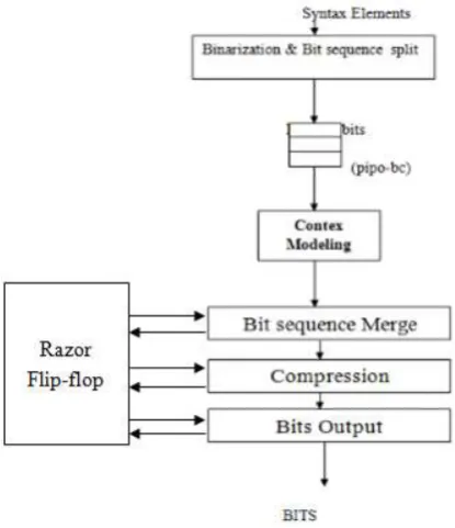
the Loss less compression. The process of Loss less compression is as follows: At initial stage the information of the image are remodeled into binary forms i.e, zero and one format (0,1). This binary information can splits into rows and columns. This can be mentioned as binarisation. During this method the binary digits can form like bits in a very sequence. These bits can forward to down as the regular bits.
Fig 2. Proposed System
These bits are ready to merge. Currently the information are united because the initial digit of the primary row with the primary digit of the primary column. During this method all the rows and columns are united. Then the binary data is prepared to compress. As we all know that, we are utilizing Loss less technique here to change the image. The image are reworked into binary information here just in case of Loss less compression. This can be very helpful Technique to achieve the precise image as we did like. In this technique, initially the binary data will be upgraded
shown with in the fig 3.
Then the image are going to be transmitted into binary knowledge i.e, zero and one format as we tend to shown in figure. Here we tend to square measure victimization 64 bit compression that is extremely helpful to the rework. Finally, this compression can send the original data as output. The ultimate output comes with none loss of information within the image, as a result of we tend to used Loss less compression technique. For this point Loss less compression is extremely advantageous and really technique than Lossy compression technique.
A 1-bit Razor flip-flop consists of a main flip-flop, shadow latch, XOR gate, and mux. The shadow latch catches the execution result using a delayed clock signal, which is slower than the normal clock signal and the main flip-flop catches the execution result for the combination circuit using a normal clock signal. The path delay of the current operation exceeds the cycle period, and the main flip-flop catches an incorrect result if the latched bit of the shadow latch is different from that of the main flip-flop. To notify the system the Razor flip-flop will set the error signal to 1 to re execute the operation if any errors occur. To detect whether an operation is considered to be a one-cycle pattern can really finish in a cycle we utilize Razor flip-flops. If not, the operation is reexecuted with two cycles. Although the reexecution may seem costly, due to the reexecution frequency is low then overall cost is low.
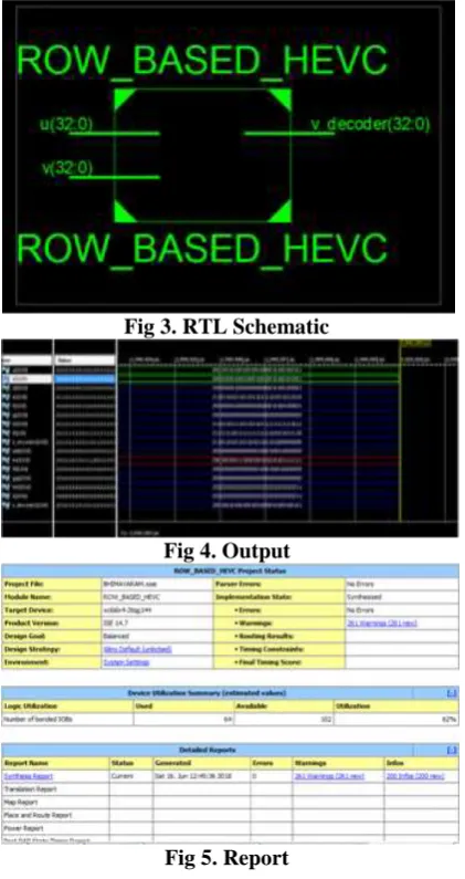
Fig 3. RTL Schematic
Fig 4. Output
Fig 5. Report
V. CONCLUSION
The emerging HEVC standard has been developed and standardized collaboratively by using the VLSI architecture. A fast integer transform VLSI architecture-based sparse signed bit transform (SBT) is proposed for real-time ultra HD video coding conforming to the HEVC standard. The integer transform matrix with high bit width is decomposed into several low bit width matrices based on matrix decomposition method. The circuit reuse strategy is used of SBT matrices to reduce number of adders in VLSI architecture. The proposed transform hardware architecture can process video data with higher speed and proper area compared with previous work.
VI. REFERENCES
[1] T. Wiegand, G. Sullivan, G. Bjontegaard, and A. Luthra, “Overview of the H.264/AVC video coding standard,” IEEE Trans. Circuits Syst. Video Technol., vol. 13, no. 7, pp. 560–576, Jul. 2003.
[2] G. Sullivan, J.-R. Ohm,W.-J. Han, and T.Wiegand, “Overview of the high efficiency video coding (HEVC) standard,” IEEE Trans. Circuits Syst. Video Technol., vol. 22, no. 12, pp. 1649– 1668, Dec. 2012.
[3] A. D. Darji and R. P. Makwana, “High-performance multiplierless DCT architecture for HEVC,” in Proc. IEEE Int. Symp. VLSI Design Test, Jun. 2015, pp. 1–5.
[4] T. Stockhammer, M. M. Hannuksela, and T. Wiegand, “H.264/AVC in wireless environments,” IEEE Trans. Circuits Syst. Video Technol., vol. 13, pp. 657–673, July 2003.
[5] S. Wenger, “H.264/AVC over IP,” IEEE Trans. Circuits Syst. Video Technol., vol. 13, pp. 645– 656, July 2003.
[6] J. Ribas-Corbera, P. A. Chou, and S. Regunathan, “A generalized hypothetical reference decoder for H.264/AVC,” IEEE Trans. Circuits Syst. Video Technol., vol. 13, pp. 674–687, July 2003.
[7] B. Bross, W.-J. Han, G. J. Sullivan, J.-R. Ohm, and T. Wiegand, High Efficiency Video Coding (HEVC) Text Specification Draft 9, document
JCTVC-K1003, ITU-T/ISO/IEC Joint
Collaborative Team on Video Coding (JCT-VC), Oct. 2012.
[8] T. Stockhammer, M. M. Hannuksela, and
T.Wiegand, “H.264/AVC in wireless
environments,” IEEE Trans. Circuits Syst. Video Technol., vol.13, no. 7, pp. 657–673, Jul. 2003.
[9] A. Ahmed, M. U. Shahid, and A. Rehman, “N Point DCT VLSI Architecture for Emerging HEVC Standard,” in Proc. VLSI Design, vol. 2012, Article 752024, pp. 1–13, 2012.