NOTICE
The information contained in this document is believed to be accurate in all respects but is not warranted by Mitel Networks Corporation (MITEL®). The information is subject to change without notice and should not be construed in any way as a commitment by Mitel or any of its affiliates or subsidiaries. Mitel and its affiliates and subsidiaries assume no responsibility for any errors or omissions in this document. Revisions of this document or new editions of it may be issued to incorporate such changes.
No part of this document can be reproduced or transmitted in any form or by any means - electronic or mechanical - for any purpose without written permission from Mitel Networks Corporation.
Mitel Networks is a trademark of Mitel Networks Corporation.
Windows is a trademark of Microsoft Corporation. SonicWALL is a trademark of SonicWall, Inc.
Other product names mentioned in this document may be trademarks of their respective companies and are hereby acknowledged.
Mitel Networks 3100 Integrated Communications Platform
Technician’s Handbook
Release 3 50002911, Revision B
August 2002
, Trademark of MITEL Networks Corporation ©Copyright 2002, MITEL Networks Corporation
Chapter 1 : Introduction
About this handbook . . . 3
Purpose of this handbook . . . 3
Who this handbook is written for . . . 3
Where you can find more information . . . 3
Symbols used in this handbook . . . 5
Important safety instructions . . . 6
About the 3100 ICP system . . . 7
Description . . . 7
Basic system configuration . . . 7
A fully expanded system . . . 8
Voice functionality . . . 8
Data functionality. . . 8
What telephone features are supported? . . . 9
Chapter 2 : Installation
Before you begin. . . 19Hardware ports and connectors . . . 19
Controller components . . . 20
Identify the required components . . . 21
Installation checklist . . . 22
Installation overview. . . 24
Installing the system components . . . 25
Configuring the PC . . . 26
Windows 95/98 . . . 26
Windows NT . . . 26
Windows 2000. . . 27
Windows ME . . . 27
Windows XP . . . 28
Launching the tools . . . 29
Running the quick installation tool . . . 30
About the system quick installation tool . . . 30
Key system, PBX, or other? . . . 30
Using the system quick installation tool . . . 31
Connect the phones and lines . . . 34
Verify the system . . . 35
Chapter 3 : Programming
Programming overview . . . 39
About the programming tools . . . 40
Tools are password protected . . . 41
Enable your options . . . 41
Programming the system parameters . . . 42
Set system date and time . . . 42
Review the numbering plan . . . 42
Set the login attributes for users. . . 43
Changing the system-wide settings . . . 45
Identify the power source of the IP phones . . . 45
Program the online services . . . 46
Programming the extensions . . . 47
Program the extensions . . . 47
Program the extension groups . . . 47
Program the extension voice mailboxes. . . 48
Program the extension personal keys . . . 48
Programming the voice parameters . . . 50
Modify the extensions and system directory. . . 50
Program the incoming access (ring maps) . . . 51
Program external access (line and hunt groups) . . . 52
Programming BRI ISDN access (UK only) . . . 53
Restrict external access (toll restriction/call barring) . . . 58
Program the voice management parameters . . . 60
Programming the voice mail settings. . . 61
Setting up the auto attendant . . . 62
Log in to the administrator station . . . 62
Record the system greetings . . . 63
Record the bilingual welcome greeting. . . 64
Configuring call logging (SMDR) . . . 65
Commit your changes . . . 67
Perform a database backup. . . 67
Programming tips. . . 68
Planning your LAN . . . 73
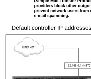
Default controller IP addresses . . . 74
IP programming sequence . . . 75
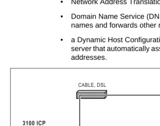
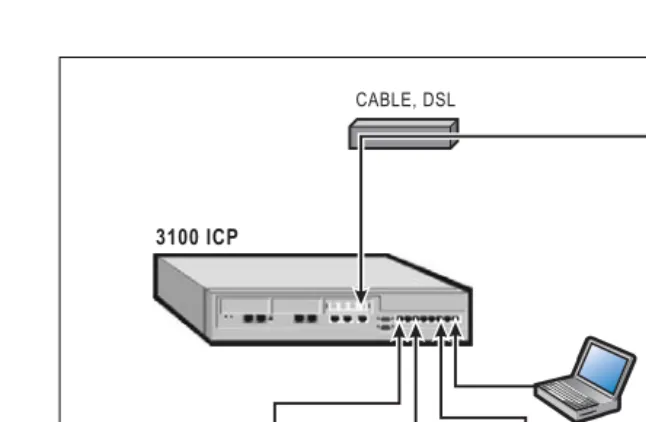
Connecting directly to the Internet . . . 76
Using Static IP addressing . . . 78
Using DHCP Client . . . 78
Using Broadband Access (PPPoE). . . 79
Commit your changes . . . 80
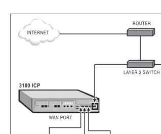
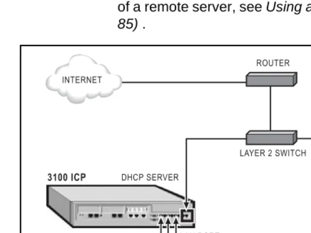
Connecting to the Internet through an existing LAN . . . 81
Through the WAN port . . . 81
Through a layer-2 switch port (custom configuration) . . . 83
Using a remote DHCP server . . . 85
What you need . . . 85
Configuring the 3100 ICP . . . 85
Configuring the external DHCP server . . . 86
Changing the assigned DHCP IP address range . . . 88
Configuring Domain Name Service . . . 91
Assigning a gateway. . . 93
Programming dial-up access to an ISP. . . 95
Restricting LAN access (firewall) . . . 97
Connecting the 6000 SBAP to the layer-2 switch port . . . 97
Connecting the 6000 SBAP to the WAN port . . . 100
SonicWALL SOHO2 . . . 102
IP networking tips . . . 106
Chapter 5 : Routine maintenance
Is the system healthy? . . . 109System health checklist. . . 109
Is the system secure?. . . 110
Checking the system . . . 111
Launching the tools . . . 113
Enabling your licensed options. . . 114
Obtain your MOSS option code . . . 114
Rebooting the system. . . 116
Powering down the system . . . 117
Upgrading the system . . . 119
Installing option modules . . . 119
Adding an expansion unit . . . 120
Performing a software upgrade . . . 121
Applying a software patch . . . 123
Replacing a flash card . . . 123
Performing backups. . . 128
Creating backup directories . . . 128
Backing up the software and/or database . . . 128
Backing up the voice mail data. . . 129
Saving call (SMDR) logs . . . 130
Using a remote access session . . . 131
Setting up remote access. . . 131
Launching the tools from a remote session . . . 133
Changing extensions or set types . . . 135
Changing an extension number or set type . . . 135
Reset the phone . . . 135
Creating a user guide. . . 136
Using a database template . . . 137
Maintenance tips . . . 138
Chapter 6 : Troubleshooting and repair
Checking the system LEDs . . . 141Checking the logs . . . 142
Viewing diagnostics . . . 143
Starting a diagnostic session . . . 143
Checking the bootup script . . . 144
Line troubleshooting . . . 145
IP phone troubleshooting . . . 146
Analog phone troubleshooting . . . 147
System troubleshooting . . . 148
Network troubleshooting . . . 149
Using Windows networking commands. . . 150
Using VxWorks networking commands . . . 152
Fixing database or software corruption . . . 153
Restoring the system with the factory software. . . 156
Restoring voice mail data . . . 157
Replacing faulty components . . . 158
Replacing the flash card . . . 158
Replacing a faulty hard disk . . . 160
Field replaceable units . . . 162
Troubleshooting tips . . . 163
Appendix A : Default database
Default Database . . . 167Numbering plan. . . 168
Numbering assignment . . . 168
Analog set configuration . . . 169
Analog line configuration (NA) . . . 169
Restriction groups (extensions). . . 169
Timers . . . 170
Feature access codes . . . 172
Appendix B : Reference
Call logging (SMDR) details . . . 177Ring Map handling . . . 179
Controller card connectors . . . 189
Port pinouts . . . 190
Line protocols . . . 194
Cable pinouts . . . 195
Appendix C : Planning
Introduction . . . 199System parameters . . . 200
Voice parameters . . . 201
Toll restriction . . . 208
Voice mail . . . 209
IP networking. . . 210
Intr
oduc
tion
About this handbook
Purpose of this handbook
This handbook provides• an overview of the system capabilities
• installation steps
• programming procedures
• maintenance checklists
• troubleshooting information
Who this handbook is written for
This handbook is for a certified technician.
Where you can find more information
Technical manual and extension guides On the system software CD-ROM
1. Insert the system software CD-ROM in the CD-ROM drive of your PC.
2. If the CD-ROM does not start automatically, open
Windows® Explorer and navigate to the CD-ROM
directory. Click Autorun.exe.
3. In the Welcome screen, click Online Help at the top of the list.
From the tools
1. After initial installation, launch your browser and go to the following URL: http://192.168.1.2
From the internet
1. Go to the following URL: http://www.mitel.com 2. Access Mitel OnLine from the Online Services
selection menu.
3. Click Technical Support and then click Customer Documentation (edocs).
User Guides through Manual Maker
Manual Maker is a web-base application that allows you to generate customized user guides
1. Go to the following URL: http://www.mitel.com 2. Access Mitel OnLine from the Online Services
selection menu.
3. Click Technical Support and then click Manual Maker.
You can also launch Manual Maker from the group administration tool.
Field change instructions
Every software release is accompanied by a Field Change Instruction (FCI). The FCI describes software changes, bug fixes, outstanding issues, and hardware compatibility considerations for the new software release. Read the FCI before you begin a software
upgrade.
The FCI is included on the system software CD-ROM. You can also obtain the latest FCI from Mitel OnLine at www.mitel.com. Note that you must be a registered user to access Mitel OnLine.
Technical Service/Information Bulletins
tion Helpful websites
For definitions of technical terms
• http://www.techweb.com/encyclopedia
• http://www.whatis.com
For networking information
• http://www.practicallynetworked.com
• http://www.networktroubleshooting.com
Terminology
Glossaries are provided in the Technical Manual and in the Installation and Maintenance Course Student Manual.
Symbols used in this handbook
A stop symbol indicates a hazardous situation which, if not avoided, could result in injury or death.
A yield symbol with an exclamation mark indicates a situation which, if not avoided, could result in damage to the equipment.
A light bulb identifies an important note or a useful tip.
A clock indicates the amount of time that is required to perform the associated step.
Important safety instructions
Intr
oduc
tion
About the 3100 ICP system
Description
The Mitel Networks™ 3100 Integrated Communications Platform (ICP) provides a complete voice and data solution in one easy-to-manage unit.
The 3100 ICP controller contains the call control software, a router, a layer-2 switch, embedded voice mail with an auto attendant, and a hard-drive for storing voice mail messages and the management tool web pages.
Figure 1: 3100 ICP controller, option modules, and expansion unit
Basic system configuration
The basic system supports• 8 Mitel Networks IP (Internet Protocol) Phones
• 2 ONS (on premise station) analog telephones
• 1 wide area network (WAN) Ethernet port for
connections to WAN services such as cable or Digital Subscriber Line (DSL)
• 4 LS/CLASS interfaces
A fully expanded system
A fully expanded system consists of the controller, fitted with three optional modules, and the expansion unit. It provides
• up to 24 Mitel Networks IP (Internet Protocol) phones
• up to 10 analog telephones with Calling Line
Identification (CLI) capability
• up to 8 LS/CLASS lines or 8 ISDN BRI lines (UK only)
The system supports a maximum of 8 lines. In the UK, these can be a combination of LS/CLASS lines and ISDN BRI lines.
• 1 Wide Area Network (WAN) Ethernet port for
connections to WAN services such as cable or DSL
• 100 IP devices.
The system supports a maximum of two ONS interface modules and one LS/CLASS module.
Voice functionality
• Full set of voice features
• Key System, PBX, or customized system
• Fully featured voice mail and auto attendant.
Data functionality
• Integrated 10/100 Mbs layer-2 switch
• Dynamic Host Configuration Protocol (DHCP) server
that supports up to 100 IP addresses
• IP Routing / WAN router, Domain Naming System
Intr
oduc
tion
• Remote WAN locations supported through Ethernet
WAN interface or dial-up Point-to-Point Protocol (PPP) connections.
• Built-in modem
• IP set powering.
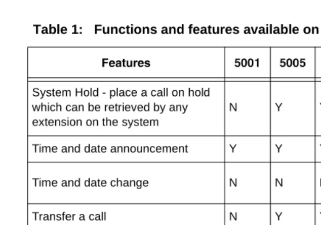
What telephone features are supported?
Note that the Mitel Networks 5001 and 5005 IP phones are not available in Release 2.3 or earlier.
Table 1: Functions and features available on sets
5TPcdaTb $ $$ $ $! $'!! $ #
Number of fixed
function/applica-tion/telephony keys 3 2 6 8 8 13
Number of personal/quick keys -- 20 7 14 14 9 Number of pre-assigned
per-sonal/quick keys -- 3 1 1 1 1
Dual or single-colored personal
keys -- single dual dual dual
--Number of soft command keys -- -- -- 3 3 6 Number of system speed call
num-bers (short codes) available 1000 system-wide
LCD display N 1 line 2 line 2 line 2 line 320x 240 VGA
Headset operation N N Y Y Y Y
Message waiting indicator Y Y Y Y Y Y Account codes - allocate to
incom-ing or outgoincom-ing calls Y Y Y Y Y Y
Adjust ringer pitch N N Y Y Y Y Adjust volume of the speaker N Y Y Y Y Y Administrator extension N N N Y Y Y Alarm calls - setup for other
exten-sion users N N N
Admin only
Admin only
Admin only Alarm calls - setup on own
exten-sion Y Y Y Y Y Y
Answer external call via
per-sonal/quick key N Y Y Y Y Y
Answer next call via personal/quick
key N Y Y Y Y Y
Auto attendant access Y Y Y Y Y Y
Automatically answer incoming
external calls (auto answer) N N N Y Y Y Automatically answer a call and
define the type of response to give N N N N Y N
Automatic hold Y Y Y Y Y Y
Bookmarks - enables the extension user to access a list of user-defined URLs.
N N N N N Y
Call status information - LCD pro-vides information about status of extension and current call
N Y Y Y Y Y
Callback when free Y Y Y Y Y Y
Calls For - identifies diverting
exten-sion number N Y Y Y Y Y
Cancel a message waiting request Y Y Y Y Y Y
Cancel call forwarding Y Y Y Y Y Y
Table 1: Functions and features available on sets (continued)
Intr
oduc
tion
Conference call - enable an exten-sion user to set-up a call between three parties
N Y Y Y Y Y
Direct Station Select/Busy Lamp Field (DSS/BLF) keys - setup at extension
N Y Y Y Y Y
Directed Message Waiting - leave a message for another extension user without calling the extension first
Y Y Y Y Y Y
Display caller’s number and name N Y Y Y Y Y
Do Not Disturb Y Y Y Y Y Y
Doorphone operation N Y Y Y Y Y
Dual Tone Multi-Frequency Tone
Dialing Y Y Y Y Y Y
Exclusive Hold - place a call on hold which can only be retrieved by the extension that placed the call on hold
N Y Y Y Y Y
Extension Groups - extension can
be associated with a group Y Y Y Y Y Y Extension Paging - broadcast a
message to a single, group or all extensions on the system
N Y Y Y Y Y
Extension Status Announcement Y Y Y Y Y N Extension-to-extension dialing -
user can dial another extension directly
Y Y Y Y Y Y
External Call Waiting - indicates that an external call has arrived when an extension user is busy on another call
Y Y Y Y Y Y
Table 1: Functions and features available on sets (continued)
Follow Me - enables calls to follow an extension user to another exten-sion within the office
Y Y Y Y Y Y
Follow Me (I’m Here) - enables an extension user to direct calls from their usual extension to their current extension
Y Y Y Y Y Y
Forward/Divert all incoming calls to another extension or extension group
Y Y Y Y Y Y
Forward/Divert calls to an external
destination Y Y Y Y Y Y
Forward/Divert incoming calls to another extension or extension group if extension is busy
Y Y Y Y Y Y
Group Listen - enables others nearby to listen to a call while allow-ing only the extension user to speak to the other party
N Y Y Y Y Y
Handsfree operation (full) - enables extension users to make and answer calls, and listen and respond to broadcast messages without lifting the handset
N N N Y Y Y
Handsfree operation (partial) - enables extension users to make calls and listen to broadcast mes-sages without lifting handset
N Y Y Y Y Y
Hotline Y Y Y Y Y Y
Identify Next Call Announcement Y Y Y Y Y Y Intrude into an established call N Y Y Y Y Y Last Call Duration Announcement Y Y Y Y Y N Last Call Duration Display N Y Y Y Y Y Table 1: Functions and features available on sets (continued)
Intr
oduc
tion
Last Number Redial Y Y Y Y Y Y
List of Calls - display the 10 most recent, different external calls to an extension
N N Y Y Y Y
Message Waiting - leave indicator
for another extension user Y Y Y Y Y Y Messaging - enables an extension
user to display a message at the calling extension, for example, GONE TO LUNCH
N Y Y Y Y Y
Monitor a call between two external
parties N N N
Admin only Admin only Admin only Night Service - place a call in night
service mode 1 or 2 N N N
Admin only Admin only Admin only Online Services - enables the
extension user to access a list of URLs programmed by the adminis-trator.
N N N N N Y
Page via the loudspeaker system Y Y Y Y Y Y Park an external call for another
extension user to retrieve N Y Y Y Y Y Personal Digital Assistant (PDA)
support N N N Y
1 N Y
Personal Directory - create entries
specific to extension N N N Y Y Y
Personal speed calls - store under personal, quick keys, or keypad keys
Y Y Y Y Y Y
Phonebook N N N Y Y Y
Pick up a call ringing at a
col-league’s extension Y Y Y Y Y Y
Table 1: Functions and features available on sets (continued)
Pick up a call ringing at another extension in the user’s extension group
Y Y Y Y Y Y
Pick up an incoming call when the system is in Night Service mode 1 or 2
Y Y Y Y Y Y
Pick up a parked call Y Y Y Y Y Y
PIN Codes - prevent unauthorised users from making external calls from an extension
Y Y Y Y Y Y
Prime Line N Y Y Y Y Y
Recall on lines N Y Y Y Y Y
Redial List - enables an extension user to save and prioritize ten exter-nally-dialled numbers
N Y Y Y Y Y
Re-establish a reverted call - attempts to re-connect the reverted call
N Y Y Y Y Y
Ringer On/Off - enables an exten-sion user to turn off the ringer for all incoming calls that arrive under a personal/quick key
N Y Y Y Y Y
Selective Ringer - enables an extension user to selectively turn off the ringer for calls that arrive under specific personal/quick key(s)
N Y Y Y Y Y
Store a call under a personal/quick
key N Y Y Y Y Y
Swap (Broker’s Call) N Y Y Y Y Y
System Directory - enables exten-sion users to dial from directory setup by the Administrator
N N N Y Y Y
Table 1: Functions and features available on sets (continued)
Intr
oduc
tion
System Hold - place a call on hold which can be retrieved by any extension on the system
N Y Y Y Y Y
Time and date announcement Y Y Y Y Y N
Time and date change N N N Admin only
Admin only
Admin only
Transfer a call N Y Y Y Y Y
Visual Voice Mail (VVM) - allows the extension user to visually interact with their voice mailbox.
N N N N N Y
Who Am I? - indicates the extension
number Y Y Y Y Y Y
1. If a Mitel Networks 5423 IRDA Module is attached.
Table 1: Functions and features available on sets (continued)
Ins
ta
llat
ion
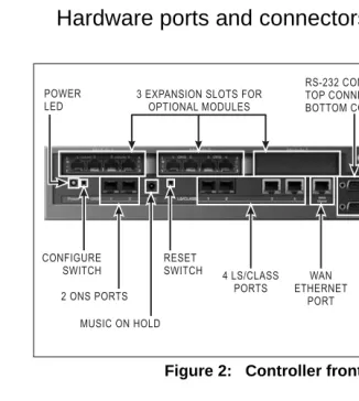
Before you begin
Hardware ports and connectors
Figure 2: Controller front panel
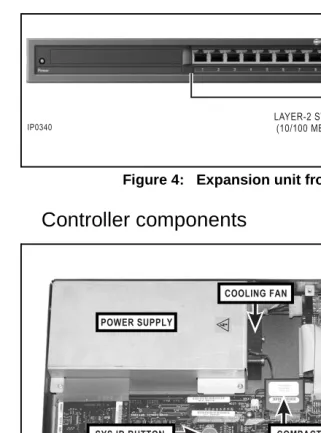
Figure 4: Expansion unit front panel
Controller components
Ins
ta
llat
ion
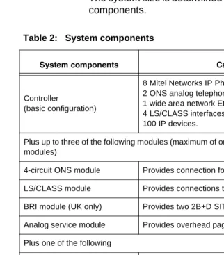
Identify the required components
The system size is determined by the type and number of components.
Up to eight lines are supported. In the UK, the eight lines can be a combination of LS/CLASS lines and ISDN BRI lines.
See A fully expanded system (p. 8) for system
maximums. Refer to the technical manual for examples of system configurations.
Table 2: System components
BhbcT\R^\_^]T]cb 2P_PQX[XcXTb
Controller
(basic configuration)
8 Mitel Networks IP Phones 2 ONS analog telephones
1 wide area network Ethernet or xDSL interface 4 LS/CLASS interfaces
100 IP devices.
Plus up to three of the following modules (maximum of one LS/CLASS module; two BRI modules)
4-circuit ONS module Provides connection for four analog phones LS/CLASS module Provides connections to four LS/CLASS circuits BRI module (UK only) Provides two 2B+D SIT interfaces
Analog service module Provides overhead paging capability Plus one of the following
Installation checklist
Tools
ã
Static strapã
Phillips screwdriverCables and connectors
ã
Category 5 (CAT5) cable for all LAN devices(IP phones, computers, servers and so forth)
ã
CAT3 or CAT5 cable for analog phonesconnected to the system
ã
RJ-45 cable and connectorsã
RJ-45 crossover (patch) cable. SeeCable pinouts (p. 195)
ã
RS-232 cable for printer.PC requirements
ã
Windows 95/NT/98/2000/ME/XP PC or laptopã
Internet Explorer 5.5 with Service Pack 2 or later,and 128 bit encryption
ã
Administrator login privileges for Windows operatingsystem.
Trunk requirements
Ins
ta
llat
ion
LAN requirements
ã
Pre-installation questionnaire completeã
Internet Service Provider (ISP)ã
Refer to Planning your LAN (p. 73) for additionalrequirements.
Other
ã
@_gUbRQbgYdXcebWU`b_dUSdY_^ã
Music on hold source (radio, tape player, or .wav file)ã
Call logging printer, call accounting package, or callInstallation overview
ã
Install system componentsã
Configure the PCã
Power up the systemã
Launch the toolsã
Run the quick install toolã
Connect the phones and linesã
Verify the systemIns
ta
llat
ion
Installing the system components
The 3100 ICP system is shipped with the system software installed and includes a default database. Option modules are shipped uninstalled.
1. If your system includes option modules, install them in the controller. See Installing option modules (p.
119).
2. If your system includes an expansion unit, install the uplink card in the controller. See Adding an
expansion unit (p. 120).
3. Wall mount the units, rack mount them, or place them on a desk or shelf. Instructions are provided on the installation sheets that are included with the units. 9Vi_eQbUgQ\\]_e^dY^WQe^Yd`_cYdY_^YdgYdXdXUVb_^d `Q^U\VQSY^Wd__^UcYTUc_dXQddXU`_bdcQ^T S_^^USd_bcQbUQSSUccYR\U
4. Connect the controller to the expansion unit with the uplink cable and Y-power cord (see Figure 17). 5. Connect the ground stud on the rear panel of the
controller to a hard-wired ground using 18 AWG (0.75mm 2/) gauge wire. The wire must have green or yellow insulation. Crimp the wire to the ground source.
6. Connect a PC to the layer-2 switch port on the controller.
Do not connect the sets to the controller at this time.
7. Power up the system. See Powering up the system
Configuring the PC
Configure your PC to connect to the 3100 ICP system.
Windows 95/98
1. From the Start menu, click Settings and then click Control Panel.
2. In the Control Panel window, double click the Network icon.
3. Click Configuration.
4. Click the TCP/IP component and then click Properties.
5. Select “Obtain an IP address automatically”. 6. Click OK.
7. Restart your PC. You are now set up to connect to the 3100 ICP system.
Windows NT
1. Login to the PC with administrator privileges. 2. In the Control Panel window, double click the
Network icon. 3. Click Protocols.
4. Click TCP/IP Protocols and then click Properties. 5. From the Adapter drop down list, highlight the device
that is being used to connect to the 3100 ICP system, then click Obtain an IP address from a DHCP server.
Ins
ta
llat
ion
7. Click Yes and then restart your PC. You are now set up to connect to the 3100 ICP system.
Windows 2000
1. Login to the PC with administrator privileges. 2. In the Control Panel window, double click the
Network icon.
3. In the Control Panel window, double click the Network and Dial Up Connections icon. Double click on the Local Area Connection. In the Local Area Connection Status Page, click Properties. 4. Click Obtain an IP address automatically.
5. From the Adapter drop down list, highlight the device that is being used to connect to the 3100 ICP system, then click Obtain an IP address from a DHCP server.
6. Click OK. You are now set up to connect to the 3100 ICP system.
Windows ME
1. From the Start menu, select the Settings tab and then Control Panel.
2. In the Control Panel window, double click the Network icon.
3. Select the Configuration tab in the Network window. This window displays a list of installed network components. Highlight the TCP/IP component and click Properties.
4. Select the radio button marked Obtain an IP address automatically.
Windows XP
1. Login to the PC with administrator privileges. 2. From the Start menu, select the Settings tab and
then Control Panel.
3. In the Control Panel window, double click the Network and Internet Connection icon. Double click on the Local Area Connection (LAN or High Speed Internet).
4. Click General in the Local Area Connection Status page and choose Properties.
5. Click General tab in the Local Area Connection Properties window. This displays a list of installed components. Highlight Internet Protocol (TCP/IP) and choose Properties.
6. Select Obtain an IP address automatically. 7. Click OK. You are now set up to connect to the 3100
Ins
ta
llat
ion
Launching the tools
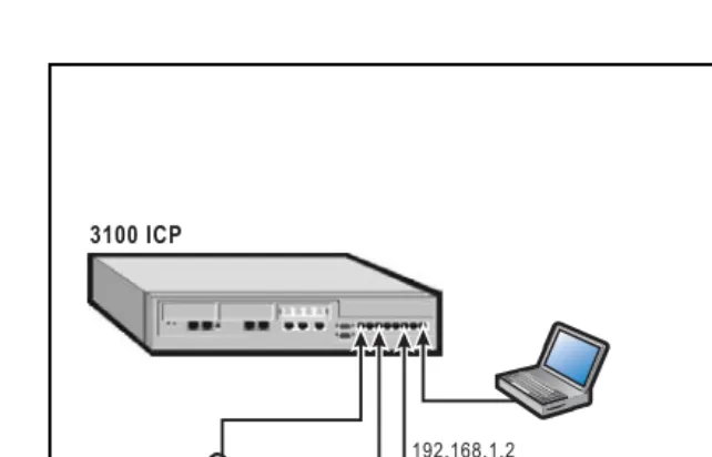
You can connect a PC or laptop to the 3100 ICP system through
• a LAN drop
• the Ethernet port on the back of the IP Phone
• directly to a layer-2 switch port on the Mitel Networks
3100 ICP controller or expansion unit.
You must configure the PC to accept an IP address from the 3100 ICP system. See Configuring the PC (p. 26). You can also access the 3100 ICP system remotely by dialing into the Mitel Networks 3100 ICP system through a trunk (using the installed V.90 modem) or through the Internet. See Using a remote access session (p. 131) for more details.
To launch a tool
1. Launch your browser and go to the following URL: http://192.168.1.2
2. Enter your username and password Login: system (default)
Password: mnet (default) 3. Click
– Group Administration Tool – System Tool, or
– System Quick Installation Tool
4. Proceed to Programming the voice parameters (p.
50).
Running the quick installation tool
About the system quick installation tool
Use the system quick installation tool to get the system up and running. All further programming is performed from the group administration tool or system tool. The system quick installation tool automatically discovers the addresses of the IP phones and assigns them extension numbers. After you exit the quick installation tool, auto-discovery is disabled. Any phone that you add later, must be programmed through the system tool.
If you install systems frequently, or if you plan to program the system at a dealer site, you should create a database template and apply it when you run the quick install tool. Using a template reduces the amount of programming required. See Using a database template (p. 137).
Key system, PBX, or other?
When you run the quick configuration tool, you are prompted to select one of the following modes
Key System Mode - Incoming calls ring all extensions at the same time
PBX Mode - Incoming calls ring one extension
Other - Allows you to load a database template into the system.
The default is PBX Mode. If you choose to change the mode to Key System or Other, you will have to reboot the system and then restart the quick installation tool. If you change the mode, after you reboot the system,
Ins
ta
llat
ion
Using the system quick installation tool
Do not close your browser window during the quick installation wizard. If you do not complete the wizard, the system configuration will be invalid. If you accidently close your browser, restart the quick installation tool and enter your information again.
You should only use the system quick installation tool once during initial installation.
1. Review the system defaults; see (p. 166).
2. Complete the pre-configuration questionnaire that was shipped with the system.
3. If you plan to change the number of digits in the extension numbering plan (for example, from the default 3-digit extension numbers to 4-digit numbers), you should set up the voice mailboxes through the administration mailbox before you run the quick installation tool.
D_cUde`dXUf_YSU]QY\R_hUc
– Connect an IP phone to a layer-2 switch port on
the controller.
– Program the mailboxes through the
administration set. See Log in to the administrator
station (p. 62).
4. Open the Internet Explorer browser on your PC. 5. Enter the following URL: http://192.168.1.2
6. In the Mitel Networks 3100 ICP login page, enter Login: system (default)
Password: mnet (default)
DXU\_WY^^Q]UQ^T`Qccg_bTYcSQcUcU^cYdYfU
Ins
ta
llat
ion
8. Click System Quick Installation Tool. The initial page opens.
9. Follow the prompts. When you are prompted to set the management tool accounts, ensure that you change the default password. When you are
prompted to connect the phones, refer to Connect the
Connect the phones and lines
When you run the system quick installation script, you will be prompted to connect the IP phones, analog phones and lines to the system. The system will not automatically recognize any IP phone that you connect after the system quick installation tool is finished.
1. Plug the RJ-45 connectors from the IP phones into the layer-2 switch ports on the controller (see Figure 2) and expansion unit (see Figure 4). The first IP phone that you connect to the system is assigned as the administrator station (extension 1000). It’s recom-mended that you connect a Mitel Networks 5020 IP phone or 5140 IP Appliance into port 1 of the controller.
DXUTUVQe\dUhdU^cY_^^e]RUbcV_bdXU9@`X_^UcQbU QccYW^UTY^dXU_bTUbdXQdi_eS_^^USddXU`X_^Uc
2. Plug the RJ-11 connectors from the analog phones into the ONS ports on the ONS modules.
3. Plug the RJ-11 connectors from the LS/CLASS lines into the line ports.
9Vi_e^UUTd_QTTc_]U9@`X_^Uc\QdUbi_eSQ^ bUU^QR\UdXUQed_bUWYcdbQdY_^_`dY_^dXb_eWXdXU CicdU]D__\3X__cUBhbcT\S\YS[BhbcT\fXST bTccX]VbS\YS[2WP]VTQ^TdXU^cUd8?bTc Pdc^aTVXbcaPcX^]T]PQ[TSd_CadT
?^fTaUPX[caP]bUTa)9V`_gUbd_dXUcicdU]VQY\cdXU ?>CcUdS_^^USdUTd_`_bd"UhdU^cY_^!! !Yc Qed_]QdYSQ\\iS_^^USdUTd_\Y^U!
Ins
ta
llat
ion
Verify the system
Complete the following procedure to verify that the system is working properly.
The system is shipped from the factory with your licensed options enabled.
1. Dial 675 on each IP phone. The extension number appears in the phone display. Record the extension numbers. The 5140 IP Appliances display their exten-sion number automatically.
2. Verify that you can make calls between the IP phones.
3. Connect an analog phone into the first ONS port on the controller.
4. Verify that you make a call from an IP phone to the analog phone (extension 1100).
5. If your system includes LS/CLASS lines, connect an LS/CLASS line to the first LS/CLASS port on the controller.
6. Place a call into the system and verify that the call rings either the first IP phone (PBX mode) or all IP phones (key system mode).
7. Verify that you can place an external call. Dial 9 to access an external line.
8. If you cannot perform all of the above tasks, check your cable connections. If the problem persists, see
Checking the system LEDs (p. 141)
Installation tips
• The first IP phone that you connect to the system is
assigned as the administrator extension (1000).
• The default extension numbers for the IP phones
(1000 to 1023) are assigned in the order that you connect the phones, starting with the administrator extension (1000).
• The default extension numbers for the analog phones
(1100 to 1109) are assigned to ONS ports (1 to 10).
• If you do not want the extension numbers to start with
the digit 1, you will have to change the numbering plan first.
• If you reinstall a Mitel Networks 5822 softphone on a
different computer, you must delete its Medium Access Control (MAC) address from system programming before you can reassign it to another computer.
• The default IP address of the WAN port is
192.168.0.1.
• You can connect loud speaker paging units that
Pr
ogr
a
m
m
ing
Programming overview
This chapter provides the key procedures for
programming the system. Refer to the Technical Manual for complete programming information.
Before you begin programming, ensure that you have
• completed the pre-configuration questionnaire that
was shipped with the system
• reviewed the default database settings. See (p. 166).
If this is a new installation, typically you will run the quick installation tool first. The quick installation tool guides you through basic programming. See Using the system quick
installation tool (p. 31).
The key steps to programming the system are
ã
5^QR\Ui_eb`ebSXQcUT_`dY_^cã
@b_WbQ]dXUcicdU]`QbQ]UdUbcã
@b_WbQ]dXUUhdU^cY_^cã
@b_WbQ]dXUf_YSU`QbQ]UdUbcã
@b_WbQ]dXUf_YSU]QY\cUddY^Wcã
Set up the auto attendantã
Configure call logging (SMDR)ã
Commit your changesAbout the programming tools
The 3100 ICP system has the following programming tools:
System quick installation tool - Use this tool once during initial system installation. Perform all further programming from the other tools.
Group administration tool - Use this tool to
• set basic system parameters
• create the system telephone directory
• manage extension and group parameters
• set group parameters
• add, edit, or delete users from the system directory
• configure voice mailboxes
• program a user’s personal keys with features
• create customized user guides
System tool - Use this tool to program the
• system-wide parameters
• voice parameters (lines, extensions, management,
system directory, and voice mail)
• IP networking parameters.
Desktop Tool - Allows users to
• assign features to personal keys
• manage personal contact lists
• manage internet bookmarks on 5140 IP Appliances.
Pr
ogr
a
m
m
ing
Before launching a new tool, you must first exit the current tool and then log in again.
If you restart or reboot the system without committing your saved changes to the database first, your changes will be lost. See Commit your changes (p. 67).
When using the system tool, always click the Exit button to leave the tool.
Tools are password protected
If you enter an incorrect password three times in succession (independent of time or re-starting the system) you will be locked out for 15 minutes. You can disable this lock-out option. See Changing the
system-wide settings (p. 45).
Enable your options
If this is a new system and you have purchased options, such as bilingual voice mail or additional IP set licenses, you must enable them. See Enabling your licensed
Programming the system parameters
Set system date and time
You can change the system date and time through the system quick installation tool, the administration tool, the administrator extension, or through the system tool. The system tool, however, allows you to set the time using either a 12-hour or 24-hour clock.
1. Launch the system tool. See Launching the tools (p.
113).
2. Choose System, from the Selection menu. 3. Click Date and Time and then click Change. 4. Enter the date in the format dd/mm/yyyy.
5. Enter the time in either 12 or 24-hour clock in the format hh:mm:ss.
6. Specify either 12 or 24-hour clock. 7. Click Save.
Review the numbering plan
The numbering plan is flexible. However, if you choose to modify the numbering plan, the programming
requirements increase significantly.
See Numbering plan (p. 168) for the default numbering plan.
To modify the numbering plan
1. Choose Voice from the Selection menu.
2. Click Management and then click Number Plan. 3. From the list of Leading Digits, click the leading digit
Pr
ogr
a
m
m
ing
4. Select the meaning (for example:
Attendant/Operator) that you want to assign to the leading digit.
5. Click Save.
To change the leading digit of the extension numbers, you must
1. Click Management and then click Number Plan. Set the number plan to allow a different Secondary entry, such as digit 4. The default is leading digit 1. 2. Choose Voice from the Selection menu, click
Extensions and then click Number Assignment. 3. Change entries in the Number Assignment form to
correspond with the new number scheme (for example, 4360).
4. Do not delete the default Secondary entry-leading digit 1 until you have changed all the numbers in the Number Assignment form (including numbers for entries with no MAC addresses) to the new leading digit.
5. Commit your changes.
Set the login attributes for users
Create user login accounts and assign the users access to the programming tools: system tool, group
Create a user login account
1. Choose System, from the Selection menu. 2. Click Login Attributes and then click Add.
3. Enter the login attributes and select the tools access. 4. Click Save.
5. After you have created the user accounts, you need to give the 3100 ICP system users their login information for the desktop tool. Send an e-mail to each user which
– provides the URL to the tools login page
– identifies the desktop user tool login username
and default password
– instructs the user to change the default password.
Changing login access
1. Choose System from the Selection menu. 2. Click Login Attributes.
3. Select the user’s name and click Change. 4. Modify the users tools access privileges. 5. Click Save.
6. Click Exit.
Pr
ogr
a
m
m
ing
Changing the system-wide settings
1. Choose System from the Selection menu.
2. Click System Wide Setting and then click Change. 3. Set the following:
– Enable or disable authorization failure lockout
– Leave IP set registration enabled (only applies to
quick install tool)
– Enter the name for the system
– Select either internal or external Music On Hold
source. 4. Click Save.
Identify the power source of the IP phones
IP phones that can either receive their power from the controller power supply or from a power adaptor that connects to the phone. Only the following phones require a power adapter:
• 5140 IP Appliances that are connected to an
expansion unit
• IP phones that have an IRDA module or PKM
attached.
Identify if the sets will receive power from an adaptor or from the controller.
1. Choose System, and then click IP Sets Powering. 2. Select the port of the phone and click Change. 3. Check the Phantom Feed box if the set will be
powered from the controller (default). 4. Click Save.
Program the online services
Users of 5140 IP Appliances can press their Online Services key to display a list of internet bookmarks. You can add, change, or delete bookmarks from this list. 1. Choose System, click Online Services
Configura-tion and then click Add.
2. Enter an Item Number. The Item Number (1 to 9) corresponds to the keys located along the right side of the set display. Key 1 is at the top.
3. Enter the label for the bookmark that you want to appear in the display (for example: Mitel Networks). Keep the number of characters in the label under 25. 4. Enter the URL of the site (for example:
http:\\www.mitel.com).
5. Click Save. You do not need to commit the database for these changes to take effect.
Pr
ogr
a
m
m
ing
Programming the extensions
Program the extensions
1. Launch the group administration tool. See Launching
the tools (p. 113).
2. Click I want to Manage Extensions. Click Add to add extension users, or select an extension and then click Edit.
3. Follow the prompts to complete the programming for an extension. Help on the fields is provided in the lower right bubble.
4. Program each extension.
Program the extension groups
After programming the extensions, add them to extension groups. The group administration tool allows you to define the
– Pickup Groups
– Night Service Groups
– Extension Groups.
The default extension group pilot numbers start at 200. You can put an extension in more than one group. 1. Click I want to Manage Groups.
2. Click Pickup Groups, select a pickup group number and then click Edit. Use the up and down arrow keys to move extensions in or out of the selected group. 3. Click OK. Repeat the above step for each pickup
group.
5. Program the Extension Groups. Follow the prompts to configure the extension groups.
6. Click Done.
Program the extension voice mailboxes
Next, program the voice mailboxes for each extension. 1. Choose I want to Manage Extensions.
2. Select the first extension and click Edit. 3. Click Modify Voice Mailbox settings.
4. Follow the prompts to configure the user’s voice mailbox.
6_bQTTYdY_^Q\TUdQY\c_^dXUf_YSU]QY\`QbQ]UdUbc S\YS[7T[_S\YS[E^XRT<PX[S\YS[?a^VaP\\X]V 2345^a\bQ^TdXU^S\YS[E^XRT<PX[Q^gTb 5^a\b
5. Click Done.
6. Repeat the above procedure for each extension that requires a mailbox.
Program the extension personal keys
The group administration tool also allows you to program an extension user’s personal keys with features. Typically, this task is performed by the user from the desktop user tool.
On the 5140 IP Appliance, this feature also assigns labels to the personal keys. The labels appear in the display next to the personal key.
To program a feature on a personal key
1. In the group administration tool, choose I want to Manage Extensions.
Pr
ogr
a
m
m
ing
3. Click Set Up/Edit Desktop.
4. Click a personal key on the phone display. 5. Select a feature from the list.
6. Click Assign to key in the lower right corner of the screen. Follow the prompts to assign the key. 7. After adding all the required features to the personal
keys, choose I want to Return to Group Administrator Tool.
8. Repeat step 2 to step 7 for each extension.
9. After programming the personal keys on the required extensions, choose I want to ... Exit.
Programming the voice parameters
For descriptions of the voice parameters, click Help, and then click Programming.
Modify the extensions and system directory
You set up the extensions from the group administration tool. You can use the system tool to make any required modifications.
To modify an extension from the system tool.
1. Launch the system tool. See Launching the tools (p.
113).
2. Choose Voice from the Selection menu. 3. Click Extensions.
4. Program the required parameters for the first extension into the following web pages in the order listed below:
– Number Assignment
– Directory Name and Allocation
– Call Pickup Groups
– Extension Groups.
5. Repeat step 4. for each extension.
6. The remaining parameters, for example, Hunt Map, Class of Service, Prime Line, and so forth, default to typical values. Change them as required.
Pr
ogr
a
m
m
ing
Program the incoming access (ring maps)
After programming the extensions and extension groups through the group administration tool, program the lines from the system tool.
Ring maps determine which extensions or extension groups receive the incoming calls from a line. Ring maps are configured on a per-line basis. Every line requires a ring map.
To program incoming line access you must configure the
• line parameters
• ring maps
• ring map types.
Configure the analog line parameters
1. Choose Voice from the Selection menu.
2. Click Lines and then click Analog Configuration. 3. Select the line and click Change.
4. Set the required line parameters. 5. Click Save.
Configure the ring maps
1. Click Lines and then click Ring Map. 2. Select the line and click Change.
3. Configure the Day and Night Entries for the line. 4. Click Save.
Configure the ring map type
3. Select either Standard or Cyclic.
If you have programmed more than one extension group in the Ring Map form, you should set the Ring Type to Cyclic.
4. Click Save.
Program external access (line and hunt groups)
To set up the outgoing lines, you need to program
• line groups
• hunt maps
• outgoing line access.
Assign lines to groups
1. Click Lines and then click Groups. 2. Select the line and click Change.
3. Select the line group that you want the line to belong to. Only lines of identical type and mode can be grouped together (that is, you can’t mix analog and digital lines).
Each line can be assigned to only one line group. By default all lines are in Line Group 1.
4. Select the line access type. On a system with only a few lines, you would typically place all the lines in one group and define the group with Both access. 5. Click Save.
Program the hunt maps
Pr
ogr
a
m
m
ing
1. Click Extensions and then click Hunt Map. 2. Select the extension and click Change.
3. Select the line groups that you want this extension to have access to.
GXU^dXUecUbQddXYcUhdU^cY_^TYQ\cdXU_edW_Y^W QSSUccTYWYddXUcicdU]Xe^dcV_bQVbUU\Y^UY^dXU\Y^U Wb_e`dXQdi_eQccYW^UTQWQY^cd5^dbi!9VQ\Y^UYc ^_dQfQY\QR\UYdgY\\Xe^dV_bQ\Y^UY^dXU\Y^UWb_e` QWQY^cd5^dbi"
9^_bTUbd_]Q[U_edW_Y^WSQ\\cUQSXUhdU^cY_^]ecd RUQccYW^UTd_Qd\UQcd_^UXe^d]Q`
4. Click Save.
Define the outgoing line access digit
By default users dial 9 to access an external line. If you want to change the leading digit for accessing an outgoing line, you must change it in the Numbering Plan. See Review the numbering plan (p. 42).
Programming BRI ISDN access (UK only)
The following sections apply to systems in the UK that support BRI ISDN access. If your system does not have BRI modules, proceed to Restrict external access (toll
restriction/call barring) (p. 58).
BRI lines for Release 3.1 are numbered as follows:
• Option module slot 1 - lines 1 to 4
• Option module slot 2 - lines 5 to 8
• ISDN system - lines 13 to 20
Configure the network response for the extensions
2. Select the first extension, click Change and select the required network response to a Direct Dial In (DDI) call. The options are
– Queue: camp incoming calls on the extension until answered
– Busy: send busy tone to calling party
– Redirect (default): redirect caller to attendant 3. Click Save.
4. Repeat the above steps for each extension.
Configure the Non-DDI BRI lines
You configure Non-Direct Dial-In (DDI) lines by using Ring Maps (similar to LS/CLASS lines).
1. Click Lines and then click Digital Configuration. 2. Select the line and then click Change.
3. Set the line type to Not Direct Inward Line. 4. Click Save.
5. Click Lines and then click Ring Map. 6. Select the line and click Change.
7. Configure the Day and Night Entries for the line 8. Click Save.
9. Click Lines and then click Ring Map Type. 10. Select the line and click Change
11. Select either Standard or Cyclic.
If you have programmed more than one extension group in the Ring Map form, set the Ring Type to Cyclic.
12. Click Save.
Pr
ogr
a
m
m
ing
Configure the DDI BRI lines
You configure DDI and MSN lines by mapping the incoming digits to any extension or extension group. 1. Click Lines and then click Digital Configuration. 2. Select the line and then click Change.
3. Set the line type to Direct Dial Inwards Line or Multi Subscriber Line.
4. Enter the Terminal Endpoint Identifier and other options as required.
5. Click Save.
6. For Multi Subscriber Lines, add the destinations for each Multi Subscriber Number (MSN) as required (maximum of 10 entries per number).
– Select the Multi Subscriber Line number in the top
part of the form.
– Click Add Member.
– Enter the Multiple Subscriber Number.
– Select the Destination Type.
– Select the Destination Parameter.
7. Click Save.
8. Assign the lines to groups. See Assign lines to groups
(p. 52).
Next, program the DDI mappings
1. Click Management, click DDI Mapping, and then click Add.
2. Enter the DDI digits required to call the DDI Target (maximum of 6 digits).
4. Enter the number of the DDI target (maximum of 6 digits).
5. Set the Day and Night Service options.
6. Select Global CLI if you want outgoing calls from a target extension to display the Calling Line Identifier (CLI) number.
7. Click Save.
Lastly, set the DDI Digit conversion for outgoing calls 1. Click Management and then click Outgoing DDI
Digit Conversion.
2. Select the DDI Digit (index number) of the line. 3. Click Change.
4. Select the Converted Digit Parameter to change the extension numbers back to the correct DDI range. 5. Click Save.
Enable least cost call routing (LCCR)
PrNet is more flexible than LCCR and allows multiple alternate routes and least cost call routing on local calls. 1. In the system tool, choose Voice from the Selection
menu.
2. Click Management, click Least Cost Routing and then click Change.
3. Enter the LCCR access digits, authorization code, and override code (supplied by the Service Provider) and then click Save.
4. Click Least Cost Routing Exceptions and then click Add.
5. Program any exception numbers that you do not want routed over LCCR and then click Save.
Pr
ogr
a
m
m
ing
7. For each BRI line, set the Enable Least Cost Routing option to Yes and click Save.
Configuring PR.Net configuration
With PrNet the default outgoing line access digit (9) must be set to Secondary in the Number Plan. When a user dials 9, the request is then routed based on the PrNet programming.
Any numbers that a user will dial must be in the
VPN/PrNet form. For example, if local calls are 4 and 6, all other digits must be covered as well, for example 1 through 9, and 0.
If local calls are to be sent over an alternative carrier you may have to include the full STD code for the local area in the Repeat Digits. For example, if local numbers begin with digit 4, and if the STD code for the local area is 01291 and the alternative carrier code is 1690, then the repeat digits could be 16904 if the carrier supports local codes or 1690012914 if the carrier does not support local codes.
1. Choose Voice from the Selection menu.
2. Click Number Plan, select the Leading Digit 9 and then click Add.
3. Set the Leading Digit Meaning to Secondary and then click Save.
4. Click VPN/PR.Net and then click Add. 5. Enter the following information:
– Access digits:
– Network Type
– repeat Access digits
– Access Type:
Restrict external access (toll restriction/call
barring)
You use restriction group levels to restrict the external numbers that extension users can call. Using class of service levels, you can control which extensions have access to external lines, local, national, and international calls. You can also program up to 20 exceptions for each group in the Global Exception form.
Set up restriction groups
Restrictions are applied from the highest restriction number to the lowest. The highest number being the least restricted; the lowest being the most restricted. See
Restriction groups (extensions) (p. 169). You can only
modify restriction groups 1 to 5.
1. In the system tool, choose Voice from the Selection menu.
2. Click Management, click Toll Restriction, and then click Restriction Groups.
3. Select the Restriction Group Number and then click Change.
4. Enter the restricted digits. Extension users will be unable to dial numbers that begin with the restricted digits. For example, if you enter the digit 1, then extensions assigned to this group will be prevented from making long distance calls.
5. Enter the maximum number of digits that users are allowed to dial. Any digit dialed beyond the maximum number will terminate the call. The default setting (0) is unlimited number of digits.
You can also specify number strings that are exempted from the restriction group.
Pr
ogr
a
m
m
ing
2. Enter the number (digit string) that you want
extension users in the restriction group to be able to call.
3. Click Save.
Assign class of service (restriction groups) to users
1. Choose Voice from the Selection menu.
2. Click Extensions and then click Class of Service. 3. Select the extension and then click Change. 4. Select the Class of Service (Restriction Group
number) that you want to assign to the extension. 5. Click Save.
Program the global exception/restriction strings Global exception strings and global restriction strings bypass all other toll restriction settings.
To program global exceptions
1. Choose Voice from the Selection menu.
2. Click Management, click Toll Restriction, and then click Global Exception Strings.
3. Click Add.
4. Enter the global exception string. For example, you should program emergency numbers (911 or 999) as global exception strings to ensure that all extensions are allowed to call them.
5. Click Save.
To program global restrictions
1. Choose Voice from the Selection menu.
3. Click Add.
4. Enter the global restriction string. You can enter up to eight digit strings that no extension can dial (for example 1900).
5. Click Save.
Set the Toll Restriction Matrix You can either allow or prevent
• Line to line routing (default is no)
• Line to line transfer (default is no)
• Line to line three-party conference (default is yes)
1. Choose Voice from the Selection menu.
2. Click Management, click Toll Restriction, and then click Toll Restriction Matrix.
3. Click Change.
4. Configure the Toll Restriction Matrix settings. These settings are system-wide.
5. Click Save.
Program the voice management parameters
1. Choose Voice from the Selection menu. 2. Click Management.
3. Program the required parameters into the following web pages in the order listed below:
– Out Access
– Timers (see page 170 for defaults)
– Least Cost Routeing (BRI - UK only).
Pr
ogr
a
m
m
ing
Programming the voice mail settings
The 3100 ICP system includes an imbedded voice mail system. To set up the voice mail system
1. Choose Voice from the Selection menu 2. Click Voicemail.
3. Program the following forms in the order listed below
• System Settings -> Voicemail Prompt Language
• Voice Mailboxes
• System Greetings -> Greetings Definition
• System Greetings -> Greetings Assignment
• System Settings -> Voicemail Options
• System Settings -> Business Hours.
For descriptions of the parameters, click Help, click Voice Mail, click Voice Mail, and then click
Programming (CDE) Procedures. Click Programming (Procedures) for detailed information.
Setting up the auto attendant
The embedded voice mail system includes an auto attendant. Setting up the auto attendant involves logging in as the administrator and then recording the greetings.
Log in to the administrator station
You must log in to the system administrator’s mailbox to record system greetings.
1. From any internal telephone, lift the handset and ob-tain dial tone.
2. Dial the auto attendant number (default 232). The system answers and plays the greeting.
3. If there is no mailbox associated with the extension, you will be prompted for a mailbox number. Enter the system administrator mailbox number (default 99, 999, or 9999 depending on the number of digits in your extension numbers).
If there is a mailbox associated with the extension, you will be prompted for the mailbox passcode. Press
∗ and then enter the system administrator mailbox
number.
The system prompts you for a passcode.
4. Enter the passcode for the System Administrator’s mailbox (default 1234).
Pr
ogr
a
m
m
ing
Record the system greetings
Greetings are recorded by accessing the administrator’s mailbox from any internal telephone. Access to the mailbox requires a passcode.
1. Log in to the system administrator’s mailbox. 2. Press [4] for the System Greetings menu. 3. Press [1] to set the primary greeting
- or-
J!LdXb_eWXJ(LV_bQ^Q\dUb^QdUWbUUdY^WcUd 4. If prompted, press [1] to assign greetings in the
default system language or [2] for the alternate language.
5. Press [1] for an Open greeting (during business hours).
-or-@bUccJ!LV_bQ3\_cUTWbUUdY^WQVdUbRecY^Ucc X_ebc
6. If prompted, press [1] to assign greetings in the default system language or [2] for the alternate language.
7. Record the greeting speaking clearly into the handset, not a speaker phone. Use the following example as a guide.
"Thank you for calling ABC Industries. If you know the number of the person you are calling, enter it now. For a company directory, press 9. For assistance, press 0 or hold for the operator. To repeat the menu options press, 3"
8. Press any key to stop recording.
9. After recording, select one of the following options:
[2] Review [3] Re-record [∗] Cancel
10. If you are recording additional alternate greetings, repeat the above procedure beginning at step 2. Do likewise to record greetings in the other language for bilingual systems.
Record the bilingual welcome greeting
If you have the bilingual voice mail option enabled, the auto attendant plays a bilingual welcome greeting when it answers an outside call. You record the greeting in the two languages selected in Voice Mail Prompt Language Form. Include in the greeting an instruction to callers to dial the Language Change Mailbox number (as specified in for service in the alternate language). The default Language Change Mailbox number is 8.
The Bilingual Welcome Greeting is only available if the Bilingual Voice Prompts Option is enabled in the Voice Mail Prompt Language form.
1. Log in to the system administrator’s mailbox. See Log
in to the administrator station (p. 62).
2. Press [4] for the system greetings menu. 3. Press [1] to set the primary greeting.
4. Press [4] to set the bilingual welcome greeting. 5. Record the greeting, speaking clearly into a handset,
not a speaker phone. The following, is a typical bilingual in English and French:
“Thank you for calling ABC Industries. Merci d’appeler les Industries ABC. Pour le service en francais, composez 8.”
Pr
ogr
a
m
m
ing
7. After finishing, select one of the following options: [1] Accept
[2] Review [3] Re-record [∗] Cancel
Configuring call logging (SMDR)
You can connect a printer to the system to obtain basic call recording, or connect a PC that is running a call accounting/management application to obtain more sophisticated reports.
You can also save call logs to a file on your PC. See
Saving call (SMDR) logs (p. 130).
1. Using an RS-232 cable, connect the printer or PC to the call logging (SMDR) port on the front of the con-troller (see Figure 6).
Refer to Port pinouts (p. 190) for the pinouts. The port settings are 9600 baud, 8 bits, No Parity and 1 stop bit (9600 8N1).
Figure 6: Call logging port 2. Launch the system tool.
4. Click Management, click Call Logging, and then click Change.
5. Set the following parameters:
– Set the cost per minute (00 to 999.9). This
functionality is not supported in NA systems
– Set the minimum call duration to be recorded
(00.00.00 to 23:59:59)
– Select the type of calls that you want recorded
– Set the minimum page length (between 10 and
225 lines) for the report. The default is 66 lines
– Enable call logging.
6. Click Save.