THERMAL TESTS OF A CP5.2 PACKAGING SYSTEM: PROTOTYPE
AND EXPERIMENTAL TEST DESCRIPTION
Rosa Lo Frano1, Donato Aquaro2 and Daniele Del Serra3
1
Researcher, DICI- University of Pisa, IT
2
Professor, DICI- University of Pisa, IT
3
Ph. D student, DICI- University of Pisa, IT
ABSTRACT
Managing radioactive waste must be carried out within a strict framework and with a constant requirement to protect human beings and the environment. A safety management of the radioactive material or waste (RAM or RW) unavoidably involves transportation activities by using robust safe and reliable packaging system.
The integrity is a crucial aspect in the design of these systems; to certify it packages should demonstrate to withstand loads, that could occur under normal and accident conditions, and to meet the safety requirements in terms of performances of containment and radiation protection, like the IAEA ones. This study deals with the thermal performances of an Italian CP5.2 packaging system aimed at the transportation of bituminised wastes, which have been evaluated by executing experimental tests in the fire scenario as specified in the IAEA regulations (i.e. engulfing fire of 800 °C for 30 minutes).
To the purpose a dedicated small scale mock-up has been designed and built at the Dept. DICI of the University of Pisa. The experimental test allowed to set up the test procedure to be adopted for the fire tests of a large scale system in consideration of risk related to the stowed bituminised wastes.
The results of the thermal test are presented and discussed.
Analysing them it is possible to conclude that the overall integrity of the packaging system is assured.
INTRODUCTION
About 20 million consignments of radioactive material take place around the world each year (IAEA, 2012), in doing that an essential component is a robust safe and reliable packaging system that is constituted, in general, by a relatively massive sealed steel structure.
To safely transport radioactive materials it is required that the packaging system must be able to guarantee the containment and confinement (integrity assurance) of the radioactive material or waste (RAM or RW) avoiding any additional dose exposure (respect of ALARA principle).
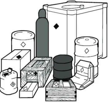
Therefore, in consideration of that, the packaging (Figure 1) must be designed according to the activity, physical state and nature of the radioactive material or waste (RAM or RW).
The design requirements set forth by the National Safety Authority and, in general, by International Atomic Energy Agency (IAEA) in (IAEA, 2012) (in Italy (UNI, 2011) and (ENEA, 1987) must be also considered) cover inspections, both prior to the first shipment and prior to each following one, the shielding, the containment, the heat transfer and criticality safety (confinement system effectiveness) of specific packaging.
This study deals with the thermal performances of an Italian CP5.2 packaging system aimed at the transportation of bituminised wastes (low and intermediate level wastes stowed in suitable cylindrical packages), which have been evaluated by executing experimental tests in the fire scenario as specified in the IAEA regulations (i.e. engulfing fire of 800 °C for 30 minutes).
In what follows, the dedicated small scale mock-up designed and built at the Dept. DICI of the University of Pisa will be described.
The thermal performances of the packaging system has been evaluated by executing the fire test in furnace at 800°C for 30 minutes. The results of the thermal test will be also presented and discussed.
Figure 1. Overview of package types.
REQUIREMENTS FOR PACKAGINGS AND PACKAGES
Before packages were firstly used, qualification tests or corresponding validated numerical simulations, covering normal and accident situations, which can be realistically envisaged in order to guarantee safety throughout the package lifetime, must be done to demonstrate their ability to withstand such conditions of transport. In particular, the accident conditions to be taken into account are:
1) Mechanical test, that consists of the three different drop tests:
1.1) horizontal, slap down, vertical, and oblique 9 m drop tests onto a flat and unyielding surface;
1.2) puncture test onto a bar (of solid mild steel of 15.0 ± 0.5 cm diameter and 20 cm long) from 1 m height;
1.3) dynamic crush test by 9 m drop of 500 kg mass (solid mild steel plate 1×1 m).
2) Thermal test that consists of 2.1 followed by 2.2:
2.2) exposure of the specimen to an ambient temperature of 38°C, subject to the solar insulation conditions, as specified in Table 12 of (IAEA, 2012), and to the design maximum rate of internal heat generation within the package by the radioactive contents for a sufficient period to ensure that temperatures in the specimen are everywhere decreasing and/or are approaching initial steady state conditions.
3) Water immersion test, under a head of water of at least 15 m for a period of not less than 8 h in the attitude that will lead to maximum damage, following the mechanical and thermal ones.
Figure 2. Sequence of possible accident conditions according to IAEA requirements.
The thermal test on the mock-up of the container CP.5.2 aimed to demonstrate that no combustion phenomena of the bitumen would occur during the furnace test at high temperature. It is worthy to note that the auto-ignition of the bitumen may occur for temperatures higher than 250°C.
DESCRIPTION OF THE MOCK-UP OF THE CP- 5.2 PACKAGING
The main design characteristics and the geometrical and material properties of such a type of packaging are defined accordingly to the UNI 11196 (UNI, 2011), which represents the Italian reference standard (National requirements).
In addition, this standards classifies the packaging types on the basis of the geometry and main dimensions as:
- cylindrical packaging system [CC];
- prismatic packaging system [CP] (the main geometrical dimension are summarized in Table 1); - modular packaging system [CM];
- special packaging system [CS].
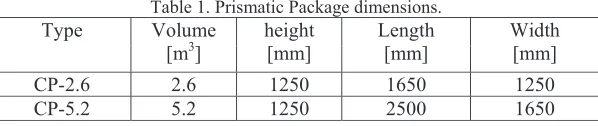
Table 1. Prismatic Package dimensions.
Type Volume
[m3]
height [mm]
Length [mm]
Width [mm]
CP-2.6 2.6 1250 1650 1250
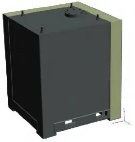
In consideration of the high potential risk related to the stowed bituminised wastes (almost six packages of them are inserted in a CP 5.2 packaging) undergoing engulfing fire conditions, 800 °C for 30 minutes, it was decided to firstly execute the fire test on a mock-up (Figure 3) of this system.
The mockup consists of a steel packaging, inside which is positioned one bituminized wastes package, of cement matrix and a closure lid with suitable gasket.
Figure 3. 3-D of scaled down packaging.
This scaled system (1:6 ratio) was representative of the whole packaging although it was not symmetric; it was entirely designed and built at the Dept. DICI of the University of Pisa. This scaling guaranteed the respect of the thicknesses of cement mortar surrounding the bituminised wastes.
As indicated in the scheme of Figure 4, the mock-up is about 1m wide, 1m length, and 1 m height.
To correctly represent the large scale packaging behaviour, two of the four outside surfaces have been thermally insulated by means of 150 mm mineral wool, so to represent the adiabatic condition (null heat flux). In addition a flange is present onto the cover lid; it allowed not only to grout cement inside the system but also behave as a filtering system during the test execution.
In the figure is shown the positioning of the thermocouples: - T1=TC16, TC17, TC18 and TC20 on the packaging surface;
- T2=TC1, TC2, TC3, TC4, TC5, TC6, TC8, TC9, TC10 and TC19 at half thickness of the cement mortar;
- T4 and T5 = TC7, TC11 on the bottom of the bituminised package;
- T3 = TC12, TC13, TC14, TC15 on the lateral surface of the bituminised package.
The positioning of T2 has been obtained by means of a sump within which was placed the thermocouple.
Figure 4. Drawings of the packaging mock-up.
Eyebolts Package with
bituminised wastes
Adiabatic surfaces
Figure 5. Thermocouples position schemes.
EXPERIMENTAL FIRE TEST: PROCEDURE AND RESULTS
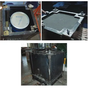
Firstly the mock-up system was realized by inserting the cylindrical package with bituminised waste into the steel outer packaging and by grouting the cement as shown in Figure 6 (all the components were of course instrumented how abovementioned).
Figure 6. Mock-up construction phase.
After waiting 28 days for the maturation of the cement, the thermal test was performed at the laboratory Scalbatraio (IAEA certified test facility (IAEA, 1987)) according to the following procedure:
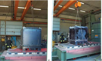
a) heating of the electric furnace until about 900°C: this highest value in respect to 800°C foreseen by the IAEA requirements is because of the decrease in temperature expected to occur during the time interval between the opening and closure of the oven hatch for the positioning of the simulacrum (about 100°C); b) opening of the oven tailgate and extraction of the slide (of 1.5x1.5 m section and 3 m length); c) placement of the mock-up (Figure 7 a);
e) execution of the thermal test at 800°C for 30 minutes: the temperatures were measured and monitored by means of an adequate data acquisition system (DAS);
f) lifting the tailgate and opening of the oven to extract the simulacrum;
h) handling of the simulacrum for the post-test cooling phase (Figure 7 b and Figure 11).
During and following the fire test, the specimen shall not be artificially cooled and any combustion of materials of the system shall be permitted to proceed naturally.
Figure 7. Positioning of the mock-up on the slide of the oven (a) and its extraction at the end of test (b) .
Results of thermal test
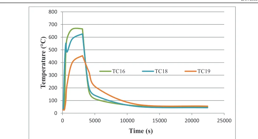
Analysing the measured temperature values, it is possible to note that, after half an hour of fire exposure at 800 °C, the temperature distribution in the bituminised waste was about 7 times lower than that on the outer mock-up surface; the same trend has been observed for the cement matrix, which resulted 4 time lower.
0 40 80 120 160 200
0 5000 10000 15000 20000 25000
T em p er a tu re ( °C ) Time (s)
TC3 TC4 TC5
TC6 TC8 TC9
Figure 8. Temperature behaviour in the cement matrix.
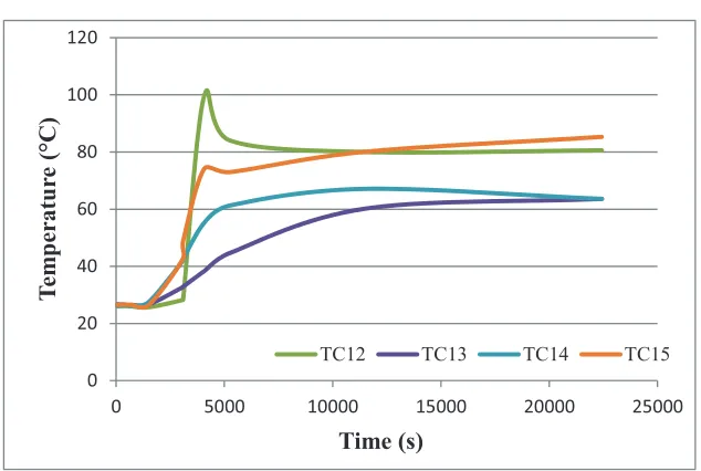
0 20 40 60 80 100 120
0 5000 10000 15000 20000 25000
T em p er a tu re ( °C ) Time (s)
TC12 TC13 TC14 TC15
0 100 200 300 400 500 600 700 800
0 5000 10000 15000 20000 25000
T
em
p
er
a
tu
re
(
°C
)
Time (s)
TC16 TC18 TC19
Figure 10. Temperature behaviour on the mock-up outer surfaces.
The maximum temperature at the cement mortar resulted also below the 400°C, limit value beyond which shortly degradation of material appears.
The maximum temperature value in the bitumen resulted instead about 100°C (Figure 9) well below the limit temperature of 250°C that represents the temperature in correspondence of which auto-ignition of the bitumen occurs.
This demonstrated that no combustion phenomena or vapour formation occurred also for a furnace test of a full scale CP 5.2 prismatic packaging.
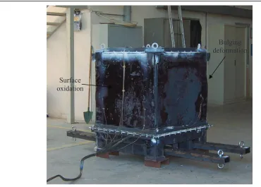
Figure 11. Overview of the mock-up after the fire test.
CONCLUSION
This study presented and discussed the thermal performances of a small scale system representative of an Italian CP5.2 packaging system aimed at the transportation of bituminised wastes.
The mock-up was designed and built at the Dept. DICI of the University of Pisa.
Taking into account the risk connected with the bitumen matrix, used to immobilize wastes, the experimental test simulating the fire scenario as specified in the IAEA regulations allowed to set up the test procedure to be adopted for the fire tests of a large scale system.
A brief description of the 1/6 packaging system (also the material and geometrical properties) has been presented as well as the procedure to execute the test (800 °C for 30 min).
The results after half an hour of fire exposure at 800 °C, highlighted that the temperature in the bituminised waste package was about 100°C: this value is below 250°C that represents the temperature beyond which auto-ignition of the bitumen occurs.
These temperature values resulted, anyway, not sufficient to attain a reduction of bearing capability or to determine severe structural damages although some outward bulging deformation and oxidation appeared on the outer mock-up surface.
Finally it was shown that the design of mock-up of the CP 5.2 packaging is able to withstand the accident conditions of transport; and demonstrated that no cliff effect or failure occurred.
NOMENCLATURE
CC cylindrical packaging system; CM modular packaging system CP prismatic packaging system CS special packaging system DAS Data Acquisition System
IAEA International Atomic Energy Agency
Bulging deformation
RAM Radioactive material RW Radioactive waste TC Thermocouple
REFERENCES
IAEA (2012). Regulations For The Safe Transport Of Radioactive Material, Specific Safety Requirements
No. SSR-6.
UNI 10621 (2011). Manufatti di rifiuti radioattivi condizionati – Caratterizzazione, UNI. ENEA, 1987, La gestione dei rifiuti radioattivi, G.T. ENEA DISP n. 26.
Lo Frano R., Pugliese G. and Forasassi G.(2011). “Thermal analysis of a spent fuel cask in different transport conditions,” Energy, 36 2285-2293.
Rains D.J. (1999). “Analysis for spent nuclear fuel multi-canister overpack drop into the cask from the multi-canister overpack-handling machine with air cushion”, SNF-5276 Rev. 0. Site-Wide Nuclear Safety Project.