c
Owned by the authors, published by EDP Sciences, 2015
Calibration of Multi-wavelength Raman Polarization Lidar
Xuan Wang1,2,a, Antonella Boselli1,3, Alessia Sannino4, Changbo Song4,5, Nicola Spinelli1,4, Yiming Zhao5, and Chao Pan5
1China-Italy Joint Research Center for Laser Remote Sensing and CNISM 2CNR-SPIN, Napoli, Italy
3CNR-IMAA, Potenza, Italy
4Dipartimento di Fisica, Universit´a di Napoli “Federico II”, Napoli, Italy
5China-Italy Joint Research Center for Laser Remote Sensing and Beijing Research Institute for Telemetry, Beijing, PR China
Abstract. The current high energy cosmic ray detection technology, including Cherenkov telescopes and fluorescence detector, is mainly limited by uncertainties in the determination of atmospheric parameters. LIDARs are currently the best suited technology to get atmospheric parameters for the atmosphere correction of high energy cosmic ray observatory data with one single instrument. A new Multi-wavelength Raman Polarization Lidar (AMPLE) has been developed and introduced in this paper. In order to provide precise and accurate results, lidar system should be calibrated before using for atmosphere correction in cosmic rays observatory. The calibration methods and results of AMPLE have been presented, including overlap function calibration, multi-wavelength channel calibration, depolarization calibration. In order to verify the accuracy of parameter measured by AMPLE lidar system, the comparison with radio sounder and sun-photometer has been done. The results show AMPLE lidar system has the ability to precisely measure the vertical profile of the atmosphere properties without any assumption and is a good choice for cosmic rays observatory to get atmosphere correction information.
1. Introduction
Cosmic rays are immensely high-energy radiation, mainly originating outside the Solar System. They may produce showers of secondary particles that penetrate and impact the Earth’s atmosphere and sometimes even reach the surface. There are several ground-based methods of detecting cosmic rays currently in use. Cherenkov telescopes have been used to detect the Air Showers from very-high-energy gamma ray (VHEGR) and fluorescence telescopes for detecting ultra-high-energy cosmic ray (UHECR). In order to detect high-energy gamma rays, charged particles and neutrinos, some infrastructures are already taking data or will take data, such as H.E.S.S., MAGIC and Pierre Auger Observatory.
In all these detection, atmosphere can alter the received signal significantly and thus give misleading results about the energy spectrum of the cosmic rays. Firstly, the vertical profile of atmosphere affects the production of Cherenkov light. Secondly, poor atmospheric quality can also result in the loss of Cherenkov light. For example atmospheric quality affects Cherenkov light propagation through Rayleigh and Mie scattering of the Cherenkov light, which can lower the brightness of an image in the camera for a shower of given energy and core distance [1]. Nowadays, the main contribution to the systematic uncertainties of imaging Cherenkov telescopes stems from the uncertainty in the height- and wavelength-dependent atmospheric transmission for a given run of data. MAGIC cites a contribution of 10% to the uncertainty of their energy scale and 12% additional uncertainty on the flux due to run-by-run variations, while H.E.S.S. retrieves 10% ae-mail:wang@na.infn.it
for the atmospheric profile, and 15% from run-by run atmospheric variations [2].
In order to correct observatory data, the atmosphere must be monitored continuously and precisely. Aerosol and clouds layer height, besides the density and type, affect the data differently, and that the position of this overdensity should be known precisely. In other words, the total extinction (or the Aerosol Optical Depth) is not a good parameter for all cases, and using only integral extinction often may lead to large systematic errors. For this reason, height-resolving instruments are required [2].
As a range-resolved active remote-sensing instrument, LIDAR has been used to get atmosphere information for correcting cosmic rays observatory data. Several lidar systems have been used in cosmic rays observatory. Most of them are elastic lidar with UV or visible wavelength. A single-wavelength elastic micro-pulse LIDAR system, operating at 532 nm wavelength, has been operated along with MAGIC telescopes. Atmospheric corrections has been used in the MAGIC data analysis, which make it possible to extend the effective observation time of MAGIC under adverse atmospheric conditions and reduce the systematic errors of energy and flux in the data analysis [3]. Another single-wavelength elastic lidar, operating at 355 nm wavelength, has been used to get atmosphere information in the measurements of the cosmic-ray air-shower fluorescence [4]. Due to the assumption of lidar ratio in the inversion of atmospheric parameters, single-wavelength elastic lidar can not get atmosphere information precisely. Raman lidar and high spectral resolution lidar (HSRL) can measure the atmosphere parameter precisely without any assumption. A Raman lidar, operation at 355 nm wavelength and three receive
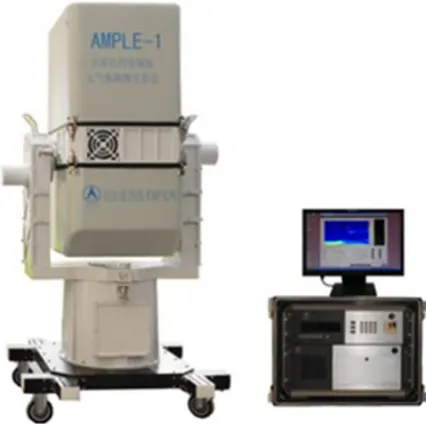
Figure 1. AMPLE lidar system illustration.
Figure 2. The application of AMPLE lidar for atmosphere monitoring.
channels, has been used to detect atmosphere in Pierre Auger Observatory [5]. A two-wavelength Raman lidar using for Cherenkov Telescope Array (CTA) is being developed by Universitat Autonoma de Barcelona (UAB) [2]. In addition, a high spectral resolution lidar, operating at 532 nm wavelength, is being developed by National Technical University of Athens [6].
We have developed a Multi-wavelength Raman polarization Lidar that can be used to get precise atmosphere information for data correction of high energy rays. Our lidar equipment and calibration methods of measurement parameters will be stated.
2. Lidar equipment
In the framework of this “China-Italy Laser Remote Sensing Joint Research Center” a new lidar apparatus, AMPLE has been designed and developed. Two sets of AMPLE has been installed, one of which is located at Beijing of China and another at Catania of Italy. The lidar apparatus (Fig. 1) and application (Fig. 2) are as following.
The AMPLE system has been designed to perform volume scanning of the atmosphere and to retrieve high quality 3D map of particulate optical properties and their time evolution. The AMPLE system is equipped with a doubled and tripled Nd:YAG diode-pumped laser that is specifically designed for this device, with a repetition rate of 1 KHz and average optical power of 0.6 W at 355 nm, 1.5 W at 532 nm and 1 W at 1064 nm. The relative high repetition rate laser source can increase the detectable signal dynamic range. Each detected signal is acquired by multi-channel scaler with a raw spatial resolution varying from 30 cm to 30 m. Moreover, polarization purity of laser line allows polarization measurements at both 355 nm and 532 nm. The lidar apparatus is able to detect both the elastic lidar returns at 355nm and 532 nm, and the N2 Raman lidar echoes at 386 nm and 607 nm. Moreover it is able to detect H2O Raman lidar echoes at 407 nm. A detailed specification of AMPLE is as following [7]. AMPLE specification:
(1) Laser source:
– Diode pumped Nd:YAG
– Fundamental, 2nd and 3th harmonics – Pulse rep. rate: 1000 Hz
– Output power: 0.6 W @ 355 nm; 1.5 W @ 532 nm; 1 W @ 1064 nm
– Pulse width 1 ns
– Linear polarization>100:1. (2) Receiver system:
– Elastic channels @ 355 nm, 532 nm and 1064 nm – Raman channels @ 386 nm (N2), 407nm (water
vapor) and 607 nm (N2)
– Depolarization @ 355 nm and 532 nm – Telescope: 20 cm Cassegrain
– Field of View: 1 mrad. (3) Scanning system:
– Elevation range: from−10◦to 100◦ – Azimuth range: from−110◦to 110◦ – Scanning speed: max 20◦/s
– Scanning angle error:<0.2◦. (4) Weight<100 kg.
(5) Power consumption<700 W.
got from the signal of water vapor Raman channel using nitrogen Raman signal as reference [12].
3. Calibration methods and result
The crucial roles of air shower measurement performed by Cherenkov or fluorescence telescopes depend on detailed knowledge of atmospheric conditions. Light from extensive air showers is produced in the atmosphere, and it is transmitted through the air to the observing telescopes. The production of fluorescence and Cherenkov photons in a shower depends on the temperature, pressure, and humidity of the air. Estimates of these air parameters in the field are further complicated by significant daily and seasonal variability in the concentration of water vapour. Moreover, as the light travels from the shower axis to the fluorescence telescopes, it is scattered from its path by molecules and aerosols [13]. From above, in order to correct the high energy cosmic ray observatory data, air transmission and the vertical profile of water vapor mixing ratio should be obtained. In order to get precise atmosphere correction information, lidar system should be calibrated before using for atmosphere monitoring in cosmic rays observatory. The lidar equation is
P(R, λ)=CO(R)
R2 β(R, λ) exp
−2
R
0
α(r, λ)dr
. (1) Here P(R, λ) is the received power, C is system constant, O(R) is overlap function, R is the distance,β(R, λ) and α(R, λ) is respectively the backscatter coefficient and extinction coefficient at distance R. The air transmission T(R), which is needed to correct the high energy cosmic ray observatory data, is given by
T (R)=exp
−
R
0
α(r, λ)dr
. (2)
β(R, λ) can be directly retrieved from the ratio of elastic and Raman signals, but O(R) must be obtained before retrieving T(R). So the first calibration is overlap function. In general, the wavelength of Cherenkov and fluorescence light are different to the wavelength of lidar, so two extinction coefficients of different wavelength are used to derivate the extinction coefficient of other wavelength in AMPLE lidar. In order to derivate precise extinction coefficients, multi-wavelength channel calibration must be done. Because the model of derivation depends on aerosol properties, the depolarization of aerosol needs to be calibrated. AMPLE lidar can measure water vapor mixing ratio directly, so the calibration is being done by comparing the lidar measurement with the radio sounder at the same place in the same time interval. In addition, the transmission comparison is being done between AMPLE lidar and sun-photometer.
3.1 Overlap function
For the typical atmospheric vertical structure, there are most part of aerosol load in planetary boundary layer, which is the lowest part of atmosphere and could be from the ground to few kilometers. Due to more aerosol
in the low layer of atmosphere, one of the major uncertainty of lidar measurement for troposphere aerosol is the determination of lidar system overlap function. The accuracy of overlap function will greatly affect the accuracy of atmospheric transmittance retrieved from lidar, so the overlap function must be calibrated firstly. There are several methods for calibration of overlap function. In this paper, we will present two common used method. One is horizontal measurement and another is iterative from backscatter measurements both Raman and elastic.
3.1.1 Horizontal measurement
One of easy way to determinate the overlap function is to do a horizontal measurement under the atmosphere horizontal homogeneous condition. In the atmosphere horizontal homogeneous condition,βandαdo not depend on the distance R. The lidar equation (1) can be simplifies as following:
log(RC S(R))=log(Cβ)+log(O(R))−2αR. (3)
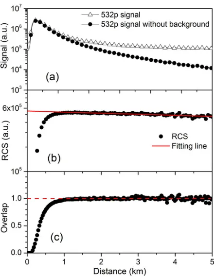
Here, RCS(R) is range-corrected signal at distance R. Overlap function, O(R), should equal to 1 in far distance. Under the atmosphere horizontal homogeneous condition, β andα are constant. The formula (3) becomes a linear function and the slope and intercept will be calculated by a linear fitting in the far range. From the difference between the fitted line and the real data in near range, lidar system overlap function, O(R), can be got. Figure3is an example of horizontal measurement result.
In Fig.3, the fitting range was choose from 1.5 to 5 km because in this range the lidar signal is fully overlapped and has a reasonable signal-to-noise ratio.
Atmosphere horizontal homogeneous condition is not always easy to meet, especially in foothills region. Even in plains region, several attempts should be made in order to find a most favorable atmosphere condition.
3.1.2 Iterative from backscatter measurements both Raman and Elastic
Another practical way to evaluate the overlap function is to compare the aerosol backscattering retrieved from only elastic signal and from both elastic and Raman measurements if the lidar system has a nitrogen Raman channel.
Figure 3. Overlap function determination. (a) Horizontal measurement lidar signal; (b) measured range corrected signal compared with the ideal horizontal homogeneous condition; (c) evaluated overlap function.
Figure 4. Iterative determination of the lidar overlap profile with Raman lidar. (a) Backscattering coefficient before iterative; (b) backscattering coefficient after 5 times iterative; (c) evaluated overlap function.
The iterative procedure has the following steps [14]. (1) Let overlap function equals to 1 for all range and to
calculate backscattering by both Klett and Raman, shown in Fig. 4a;
(2) Use the ratio of two total backscattering (aerosol + molecular) as new overlap function;
(3) Use the new overlap function to recalculate the backscattering by Raman. In this way, the transmittance part will evaluate more precise and hence the backscattering;
Figure 5. The multi-wavelength channel calibration of AMPLE lidar.
(4) Repeat the step (2) and (3), until the Raman backscattering remains stable.
Usually, 3–5 steps will be enough to get the convergence – overlap function.
The limitation of iterative method is that we use a constant value for the lidar ratio, which is used for Klett retrieval. This condition is true only if in the un-overlapped range (first kilometer) it contains a unique type aerosol.
3.2 Multi-wavelength channel calibration
For multi-wavelength lidar, the consistency of different wavelength channel is very important. It is one of the crucial preconditions to get aerosol optical parameter for all visible wavelengths from one in lidar wavelengths. Aerosol backscattering Color Index (CI) is used to represent the wavelength dependence of the backscatter coefficient. The expression of CI is
C I =
log
β532
β355
log355532· (4) Here β532 and β355 are backscatter coefficient in the wavelength of 532 nm and 355 nm, respectively. Due to the different types of aerosol, CI can vary from−1 to 4. For cirrus cloud, the backscattering coefficient is independent on the wavelength of lidar. This means that CI should equal to zero. So, cirrus cloud is an ideal object for the calibration of different wavelength channel. In Fig.5, the 24 hours continuous measurements shows there are few hours’ cirrus cloud in the range from 9 to 11 km beside several aerosol layers in the low altitude. The measurement was carried out in August 2013 in Dunhuang, North-West of China, by AMPLE lidar system.
In Fig.5, the range used to calculate the CI is indicated as dash line box. The weight average value of CI by aerosol backscattering is 0.12±0.15, which is comparable with zero. This means that from two channels, 355 and 532 nm, we got the nearly the same value of aerosol backscattering and the AMPLE lidar system is well calibrated between 532 and 355 nm channel.
3.3 Depolarization calibration
Figure 6. The depolarization calibration of AMPLE. (a) RCS of 532 p channel and air molecule line; (b) the result of depolarization calibration of AMPLE by pure molecular scattering signal (depolarization equals to 0.365%, shown by dash line).
particulate. Due to the different gain of the channels used in lidar or to the different transmission optical efficiency, the depolarization is not equal to zero even if the aerosol shape is spherical. In order to measure the aerosol depolarization precisely, the depolarization calibration of lidar system must be done.
AMPLE lidar system use depolarizer plate plus air molecules to calibrate the depolarization. Depolarizer plate is used to make the return light unpolarized and calibrate the difference of gain between parallel polarization channel and perpendicular polarization channel. Since the emitted light from laser is not completely polarized light and optical components drawbacks also bring depolarisation, calibration by depolarizer plate is not enough. Since the depolarization ratio of atmosphere molecules is determinate in the lidar system using very narrow filters (depolarization equals to 0.365% in 532 nm) [15], pure molecular scattering profile is used to calibrate the depolarization of AMPLE further. Figure6shows the result of depolarization calibration using depolarizer plate plus air molecules. The measurement was carried out in August 19, 2013 in Dunhuang, North-West of China, by AMPLE lidar system.
The procedure of depolarization calibration in AMPLE system has two steps. The first step is the correction of gain ratio by using depolarizer plate in the receiver. The second step is the correction of the depolarization caused by transmitting and receiving optical systems using pure molecular scattering. In Fig.6a, range corrected signal of 532 nm channel coincides with air molecular profile when the altitude is above 6 km, which means the backscattering in the height of above 6 km is pure molecule scattering. Backscattering signal from the height of 6 km to 10 km has been used to correct the remaining polarization after the correction of gain ratio. Figure6b shows the depolarization ratio profile calculated by parallel polarization channel and perpendicular polarization channel in the wavelength of 532 nm. The insert figure shows an enlarged view of the depolarization ratio profile from 6 km to 10 km.
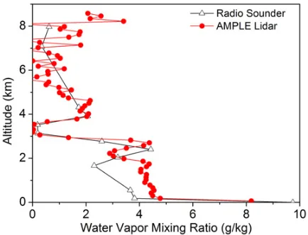
Figure 7. The comparison of water vapor mixing ratio between AMPLE lidar and Radio Sounder.
The average value of depolarization ratio in this range is about 0.365% (dash line in Fig.6b), which equals to the depolarization ratio of pure atmosphere in 532 nm. The depolarization ratio of low atmosphere layer (height 0 3 km in Fig.6b) is about 5%, which is a typical depolarization ratio of the aerosol in planetary boundary layer.
3.4 Water vapor mixing ratio test
The water vapor Raman channel (407 nm) of AMPLE allows us to measure water vapor mixing profiles in the atmosphere. The comparison was done between AMPLE lidar and radio sounder in August 20, 2013 in Dunhuang, China. Radio sounding balloon was released at 22:30 and collected data from ground to 20 km for about an hour. AMPLE lidar data obtained in first half an hour was used to compare with radio sounder. The result of comparison is shown in Fig.7.
In Fig. 7, the water vapor mixing profile from AMPLE lidar was retrieved by the signal of water vapor Raman channel (407 nm) and N2 Raman channel (387 nm). The measured water vapor mixing profile was calibrated by the relative humidity near ground. The water vapor mixing ratio from Radio sounder is calculated by measured relative humidity profile. Figure 7 shows the two water vapor mixing ratio profiles are approximately consistent.
3.5 Comparison with Sun-photometer
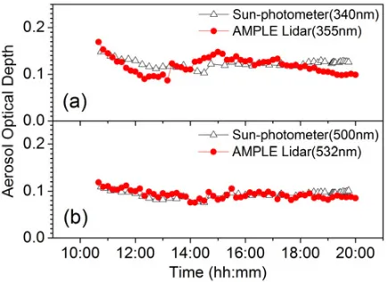
Figure 8. The comparison of AOD between AMPLE lidar and Sun-photometer. (a) AOD from 355 nm channel of AMPLE lidar and 340 nm channel of Sun-photometer; (b) AOD from 532 nm channel of AMPLE lidar and 500 nm channel of Sun-photometer.
atmosphere transmission. Figure 8 is the result of comparison in August 20, 2013 in Dunhuang, North-West of China, by AMPLE lidar system.
In Fig. 8, AOD from AMPLE lidar is calculated by integrating the profile of atmosphere extinction which is retrieved by Klett method using a lidar ratio profile, which is obtained from AMPLE in the night of the same day by using Raman channel and elastic channel. Figure 8b shows AOD from AMPLE and AOD from Sun-photometer are very consistent. This means AMPLE can get AOD of atmosphere precisely. The reason of the bias in Fig.8may be the change of lidar ratio.
4. Conclusion
A Multi-wavelength Raman Polarization Lidar (AMPLE) has been developed and calibrated. The calibration methods, including horizontal measurement method and iterative method for overlap function calibration,
multi-wavelength channel calibration method by using cirrus cloud, depolarization calibration method by depolar-izer plate plus air molecules, have been presented. In order to verify the accuracy of parameter measured by AMPLE lidar system, radio sounder and sun-photometer have been used to compare with AMPLE lidar.
The results of calibration and comparison show AMPLE lidar system has the ability to precisely measure the vertical profile of the atmosphere properties without any assumption. So, AMPLE lidar is a good choice for cosmic rays observatory to get atmosphere correction information.
References
[1] C.B. Rulten and others, 1st AtmoHEAD Conference (2013)
[2] M. Doro and others, ICRC (2013) [3] C. Fruck and others, ICRC (2013)
[4] A. Filipcic, M. Horvat, D. Veberic, D. Zavrtanik, M. Zavrtanik, Astroparticle Physics 18, 501–512 (2003) [5] L. Wiencke, A. Botts et al., ICRC (2011)
[6] P. Fetfatzis et al., Conference on Nuclear and Particle Physics (2009)
[7] Y.M. Zhao et al. IJRSA 3, 240–244 (2013)
[8] A. Ansmann, U. Wandinger. Appl. Phys. B 55, 18–28 (1992)
[9] J. Klett, Appl. Opt. 20 (2), 211–220 (1981)
[10] A. Ansmann et al., Optics Letters 15 (13), 746–748 (1990)
[11] G. Pisani et al., Atmospheric Environment 62, 34–40 (2012)
[12] D.N. Whiteman, Appl. Optics 42 (15), 2593–2608 (2003)
[13] Segev BenZvi, ICRC (2009)
[14] F. Navas-Guzm´an, Opt. Pura Apl. 44 (1), 71–75 (2011)