301 |
P a g e
IJARSEMULTI LIMB TRANSFORMER
Akhil K J
1, Shelton Shibu
2, Rajath P
3, Mr.Dhanoj M
41,2,3,4
Vimal Jyothi Engineering College, Chemperi, Kannur
ABSTRACT
Usually transformers are available in cubical or circular shapes, but due to the fixed shape of transformer the flexibility in the size and shape of the electronic and electrical devices are restricted. In order to give more flexibility to the shape and size of electrical and electronic devices here introduce a new design of transformer, named “MULTI LIMBTRANSFORMER”. The special property of multi winding transformer is that it is
compact, it can be made with different length, and breadth and height according to our requirement rather than conventional transformer in, and its design consist of a single phase transformer with four windings, in their four limbs which is considered as a unit building block. By combining a number of such blocks together, we can perform the function of a transformer. The voltage and current requirements can be obtained by the series and parallel combinations of the windings. The size of the unit block is very low compared to the total size of a transformer, therefore the properties of a small transformer, like low reluctance, length of the conductor per turn, leakage flux, effective length of core thereby reduce the heat loss, eddy current loss and hysteresis loss. This enables the design to be more efficient than the conventional transformers. The importance of this transformer over other transformer is its flexibility in shape. High power electronic devices (equipment’s) such as power amplifiers, high power consuming computers, microwave ovens, inverters, SMPS, the size of the transformer is a main factor. The flexibility in the shape of this transformer makes the design of these type of devices more efficient.
I. HONOR OF OUR OWN INTRODUCTION
A transformer in its simpler form consist of two windings on a laminated iron core. The winding connected to
the source voltage is called primary winding and the other connected to the load is called the secondary winding.
When an AC voltage is applied to the primary,current flows through the winding which creates an alternating
magnetic in the iron core. The flux cuts the secondary winding and induces voltage in it. This is the basic
working principle of a transformer. The transformer consist of a single double winding with a common
laminated core. In multilimb multiwinding transformer, there is number of small windings which are
surrounding the limbs of a single core, which enables all the things as single units. The variations in any
parameter in any winding will be distributed to all windings and the self-balancing of the transformer is
achieved as a normal transformer. By splitting the entire winding and limbs into more, the size of the basic
block in very low and combining of them can be made in our required shape, which enables the formation of the
transformer according to customized design. Each windings are connected in series or in parallel according to
302 |
P a g e
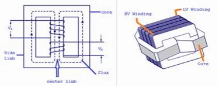
II. ORDINARY TRANSFORMER
A transformer is a static electrical device by which the voltage (or electromotive force) of a source of alternating
current may be increased or decreased. Transformer can be: shell type, core type and berry type.
Figure 1: ordinary transformer
2.1 Principle of a transformer
The principle of a transformer on which a transformer works is electromagnetic induction, which states that
induced emf in a conductor is proportional to the rate of change of magnetic flux.
1) An iron core: is either circular or rectangular in shape and is laminated (to avoid eddy current). The vertical
portion of the core is called limb. While the top and bottom portions are the yokes.
2) Winding: Transformer consist two windings, one connected to the source of the electrical source (called
primary). While the other connected to the load (called secondary). These windings are coils. A different
number of turns, wounded around the new limbs of the core. Each winding is properly insulated from and each
other as well as the core.
2.2 Theory of working
An alternating voltage (V1) applied to the primary winding (of N1 turns) circulates an alternating flux (ø). In the
core, the flux thus produced expands and contracts and cuts the turns of windings and induces voltage on both
the primary and secondary windings. In our ideal transformer, the whole of the magnetic flux produced by the
current pass through the iron core. In other words, magnetic flux linked with every turn of primary or secondary
coil is same at any instant. The varying magnetic flux linked with the secondary produces an induced emf or
voltage (V2) across the secondary coil. If ø is the magnetic flux linked with each turn of the primary and
secondary coil then
V1=-N1(dø/dt) ---(1)
Where (dø/dt) is the rate of change of magnetic flux in each turn of the primary coil. Also rate of change of
magnetic flux in each turn of the secondary at any instant is
V2=-N2(dø/dt) ---(2)
Dividing equation (2) by equation (1), we get
V2/V1=N2/N1= k
Total emf induced in secondary/Total emf induced in primary = No of turns in secondary/No of turns in
303 |
P a g e
III. MULTILIMB TRANSFORMER
The normal transformer consisting of the windings (primary and secondary) on their limbs. The multilimb
transformer, the number of limbs is grown at a much more than the conventional type transformer. The whole
windings are distributed equally among these limbs. So each limb carry a part of the winding. The windings on
each limbs are connected either in parallel, series connection or it can be a combination of series and parallel
connection, according to the voltage and current requirement. So the current (in the case of parallel winding) or
voltage (in the case of series winding), in each windings are added up and provide a suitable output. The
primary and secondary windings are similar in structure. The turns ratio and the thickness of the conductor is
made in such a way that to carry the required amount of current.
Figure 2 multi limb transformer
3.1 Classification of Multilimb Transformer
1)
Parallel axis winding type:-
This is a type multilimb transformer in which the axis of windings are parallel to the core of the transformer.
The working of this type is same as the conventional transformer. It is an extended version of core type
transformer. So it’s the basic building block and is same as that of core type transformer. The core contains
number of limbs. Each limb contains primary and secondary windings which are arranged in such a way that the
flux is produced by each winding should be added up. If any changes in the direction of flux in order to make a
situation like the flux in one winding opposed by the flux produced by another winding. This dissimilarity in the
arrangement of flux, cause the formation of an opposing force within the core, which decreases the induced emf
in the winding also makes current in reverse direction of the load current, which decreases the power delivered
from the transformer.
Figure 3 parallel axis type multi limb transformer showing the direction of magnetic flux and
304 |
P a g e
3.1.1Theory
The parameters and working of multilimb transformer is same that of conventional transformer. The primary
and secondary windings are wounded on each and every limbs. The flux produced by the primary winding
circulate through the core and which cuts the conductor in the primary and secondary winding and induces an
emf in both the windings. The emf induced in the primary winding makes an opposing emf against the supply
voltage. The voltage induced in the secondary winding is taken as the output.
The voltage induced in the transformer depends upon the number of turns, maximum flux and frequency
That is e=4.44øNf
The copper loss in the transformer depends on length of the conductor. As the length increases the copper loss
increases. If we split the whole conductors into of a large single winding into small windings, the length of the
conductors per turn can be reduced. So the copper loss can be reduced as well as the heat generated also will
reduce. When we increase the number of windings, the total flux is also divided so that the induced emf per turn
is less than that of the normal transformer. The lowering in the induced emf can be compensated by series
combination of adjacent winding. As the total winding divides the current into a different number of windings
which reduces the current to windings by a factor same as that of the number of windings.
3.1.2 Working Principle
The working principle is same as that of normal transformer in which emf induced in the windings are according
to the Faraday’ s law of electromagnetic induction, which states that the change in magnetic flux produces an
emf in induced in a conductor associated with it. The change in magnetic flux is produced by an alternating
voltage applied to the primary winding of the transformer.
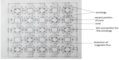
3.1.3 Design
Except some features in its design multilimb transformer issimilar to that of normal transformer. In multilimb
transformer, core consists of more number of limbs so that the magnetic flux is distributed in more number of
path. In this distributed path the magnetic flux produced in one direction should not opposed by the other
magnetic flux produced by the other winding. If the flux produced by one winding is cancelled by the other will
lead to the reduction of the induced emf in the winding and also the winding do not possess any magnetic
property which makes it as short circuited path and it in turns which leads to the power dissipation with the
transformer. In order to avoid this situation, each and every magnetic flux should be added. For arranging the
flux in a particular direction in every limb, the dot convention can be considered. In the case of this transformer,
the portion of the core that contain the dot convention should be arranged alternatively in a diagonal manner.
The direction of the flux in the core can be determined by the left hand rule. We can change the directions of the
magnetic flux by changing the direction of current entering the winding or by changing the position of the
winding. Here we place the winding which obey the condition given above (shown in the figure). This
arrangement of winding can be applied to both primary and secondary winding.
Core of the multilimb transformer also should be laminated for reducing the eddy current loss particular way.
The number of turns in the winding can be adjusted according to the voltage or current requirement. The gauge
of the conductor can be adjusted according to the capacity of the conductor to carry the maximum current
305 |
P a g e
3.1.4 Working
The working of multilimb transformer is similar to that of normal transformer, but the flux in the core are
aligned in a particular direction in which the flux from the adjacent windings are added up. As the transformer,
the ac source voltage is connected to the primary winding which produces a change in flux as the Faraday’s law
of electromagnetic induction. Each of the primary windings are connected in series or parallel. There is no phase
difference between the windings, so every winding produce flux in same phase. The flux in core is cut by each
secondary windings which induces an emf in it, which means that the induced emf is proportional to the rate of
change of magnetic flux and the perimeter of one closed path is very low so that leakage flux becomes very low
and makes the transformer more efficient. The induced emf in the secondary is tapped out and connected to the
load which takes the load current from the secondary. This current in the secondary makes the magnetic flux
oppose the main magnetic flux in the core and which makes the current in the primary winding proportional to
the load current which makes the power in primary and secondary equal (excluding the loss). The flux in one of
the winding is associated with other windings which are in the adjacent limbs, so any change in the current or
voltage in one of the winding makes the corresponding change in the flux produced by it. The change of flux
make a corresponding change in the induced emf and current in the adjacent winding associated with that flux.
Each and every windings are in same core, which are connected as a network. So any change in one winding
will transmitted over the entire windings, so the self-balancing of the transformer is done by the entire windings,
as a single unit. This makes the voltage regulation of the multilimb transformer is same as normal transformer.
2)
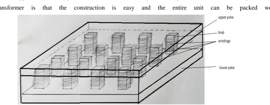
Perpendicular axis type.
If the axis of multi limb transformer is perpendicularto the flat core, then it can be named as perpendicular axis
multi limb transformer. The working is same as that of the parallel axis transformer and all the other conditions
are also applicable in this type of transformer. The advantage of this type of transformer over the parallel axis
transformer is that the construction is easy and the entire unit can be packed well.
Figure 4:-perpendicular axis type multi limb transformer
3.1.5 Design:
As shown in the figure below this type of transformer is contain an upper and lower plate which are connected
by the limb perpendicular to the parallel plates. The winding can be placed in the limbs. The direction of the
flux can be fixed by the dot convention. Which is same as that of the parallel axis type. The material of the core
suggested as a low reluctance material and the gauge of the conductor is adjusted for the maximum current
306 |
P a g e
3.1.6 Working:
Same as the parallel axis type.
4
.ApplicationsCan reduce the size of devices that use transformers.
The flexibility of transformer aids in modification of configuration of devices.
5. Advantages of multi limb transformer:
Flat in shape:
The special design the transformer flat and which is suitable where cubical or cylindrical shape are imperfect.
Efficiency:
Total winding is divided into different so the current in one winding is low so the copper loss can be reduces.
The length covered by the flux of one core is low so the hysteresis loss and the loss due to the leakage flux
become less. So the efficiency become high.
Taping is possible:
Self-balancing and voltage regulation is possible so taping from each winding is possible.
It is also suitable for 3-phase systems:-
The three dimensional structure of multi limb transformer can be act as a 3-phae transformer.
5. Disadvantages:-
The design is complicated than the normal transformer.
It may costly.
REFERENCE
[1] Electrical Engineering by Jain and Jain.
[2] Electrical machines by BL Theraja.
[3] www.electronic-tutorial.ws
[4] Transformer Design Principles-RajendraAhuja
[5] www.electrical4u.com