Use of PLC and SCADA in Mechanization of
Elevated Services Reservoir
Mayuri D. Jundhare
1, RuchitaA. Jadhav
1, Neha G.Kalaskar
1, S. K. Gaikwad
2UG Student, Dept. of E & TC, Pimpri Chinchwad College of Engineering, Akurdi, M.S., India1
Assistant Professor, Dept. of E& TC, Pimpri Chinchwad College of Engineering, Akurdi, M.S., India2
ABSTRACT: Automation plays a vital role in process and manufacturing industries. Automation has revolutionized the world in almost all the productivity with the increased reliability, improved quality and efficient as well proper utilization of the resource. The water given to the each region was not managed properly depending on the requirement leading to wastage of the water and insufficiency of the water to another region. Using Programmable Logic Controller (PLC) we made automatic control of the elevated service reservoir which was done earlier manually and we also did collection, analysis and control of the data using Supervisory Control and Data Acquisition ( SCADA).
KEYWORDS:PLC, SCADA, Level transmitter, Flow transmitter, Pressure transmitter.
I.INTRODUCTION
In urban area water supply has been made through Elevated Service Reservoirs (ESR). The pure water from water treatment plant (WTP) is carried through water lines and elevated reservoirs are filled with water in different timings of the day and night. When elevated service reservoir is completely filled water, the water is supplied by opening valve of the ESR by valve-man but sometimes due to carelessness of these valve-man difficulties are encountered in regulating water supply. Hence there is need to overcome this problem using programmable logic controller (PLC) which takes and executes the decision without any human intervention. We have used various automation devices like the ultrasonic level transmitter, pressure transmitter, and electromagnetic flow transmitter. Earlier the level was measured by the level gauges which are replaced by the ultrasonic level transmitter which gives précised and accurate value. PLC is again interfaced to SCADA (Supervisory Control And Data Acquisition System) unit so as to monitor, control and collection of level, pressure and flow of the water.The main advantage of using SCADA is that all the parameters measured can be stored in its memory and used whenever required. SCADA provides multipurpose utility management and operating flexibility for monitoring the system.
The objective of this work is to reduce human interference by using various electronics instruments, PLC and GPRS system.This gradually decreases the human faults and errors. Also, carry out analysis of the day to day data of water level, inlet water pressure which is very beneficial for carrying out the analysis as well as managing the amount of water in that region if there causes some insufficiency. Real time monitoring, central monitoring of automation of ESR and to send the data from workplace to control room and concerned fields engineers.
II.LITERATURE REVIEW
node consecutively hops on FHS within a given order to transmit and receive a coordination packet. The aim of coordination packet that is generated by a node with message is to inform its path about the frequency channel decided for the message copying.
Furthermore, the coordination packet is assumed to be small enough to be transmitted within slot duration. Instead of a common control channel, FHS provides a diversity to be able to find a vacant channel that can be used to transmit and receive the coordination packet. If a hop of FHS, i.e., a channel, is used by the primary system, the other hops of FHS can be tried to be used to coordinate. This can allow the nodes to use K channels to coordinate with each other rather than a single control channel. Whenever any two nodes are within their communication radius, they are assumed to meet with each other and they are called as contacted. In order to announce its existence, each node periodically broadcasts a beacon message to its contacts using FHS. Whenever a hop of FHS, i.e., a channel, is vacant, each node is assumed to receive the beacon messages from their contacts that are transiently in its communication radius.
III.PROPOSED BLOCK DIAGRAM
The Fig. 1 shows the block diagram consists of level transmitter, pressure transmitter, flow transmitter and the GPRS module.
Fig.1. Block diagram
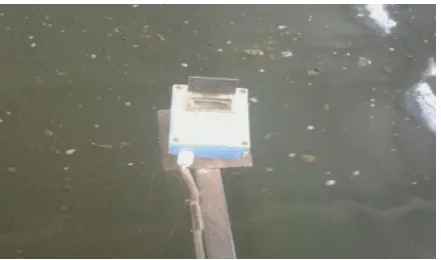
A. Level Transmitter
Ultrasonic level transmitter is shown in Fig. 2 which is used manufactured by the Forbes Marshall. In this, ultrasonic waves are transmitted and received and used to measure the level of the water. The level of the water in elevated service reservoir is also displayed on the SCADA.
B. Pressure Transmitter
The pressure transmitter used in DP cell manufactured by the SIEMENS. This DP cell works on the principle of the pressure difference on both side of transmitter and thus the pressure of incoming flow is measured. Fig. 3 shows the Siemens pressure transmitter
Fig.3. Siemens pressure transmitter
C. Flow Transmitter
Electromagnetic flow meter manufactured by the Khrone Marshall is used to measure the flow of incoming water which is shown in Fig.4. According to the given set point of the flow will be compared with the flow measured with the transmitter .This will be also displayed on SCADA screen.
Fig.4. Electromagnetic flow meter
D. GPRS System
General Packet Radio Service (GPRS) system is communication medium used to transfer the data to the operator station which is SCADA room where all the data is collected ,gathered and displayed on the screen. In GPRS, the data is in the form of packets, which is usually a 2.5G. Fig. 5 shows the
GPRS modem.
E.Programmable Logic Controller
The PLC accepts the input from flow transmitters, pressure Transmitter, level Transmitter and compares it with the benchmarks already fed into the PLC. The error between the actual reading and benchmark will modulate the final control element to Codesys software linked with the PLC. PLC is also programmed to send messages if the problem occurs when system in progress.
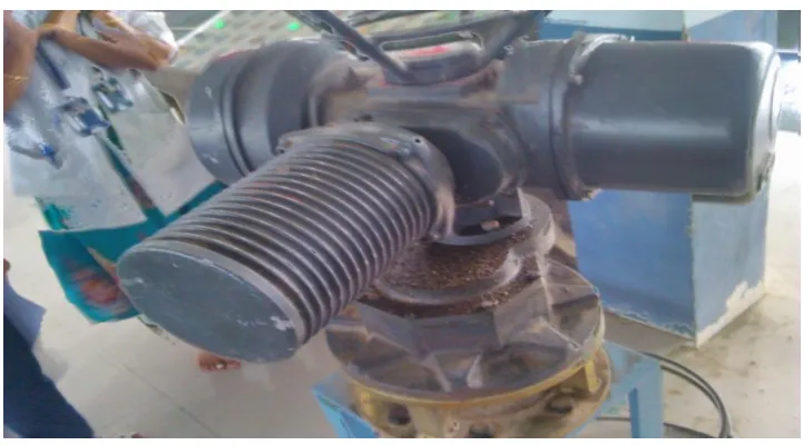
F. Electric Actuator
The electric actuator we are using is manufactured by the Marsh. Fig. 5 shows Marsh electric actuator.
Fig. 6 Marsh electric actuator
IV.WORKING OF THE SYSTEM
V. RESULT AND DISCUSSION
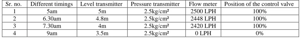
Table 1. Different values at different time of flow meter, pressure transmitter, level transmitter
Sr. no. Different timings Level transmitter Pressure transmitter Flow meter Position of the control valve
1 5am 5m 2.5kg/cm² 2500 LPH 100%
2 6.30am 4.8m 2.5kg/cm² 2448 LPH 100%
3 7.30am 4m 2.5kg/cm² 2420 LPH 100%
4 9am 3.5m 2.5kg/cm² 0 LPH 0%
From the table it is revealed that f low meter shows the approximately same reading resulting the level in the ESR decreases constantly by half an hour.
VI.CONCLUSION
We conclude that by this idea of automation of elevated service reservoir, water will be saved and used carefully. Now we can also have a watch on the current status of water supply through SCADA. All the required information can now be received directly from the work field without even being there physically. The overall control can be carried out with ease. The water distributed to each region is managed properly depending on the requirement without leading to wastage of the water and insufficiency of water to other regions. This process is carried out with high efficiency because of the reliable automation component ie. PLC. Due to the use of HMI with PLC it has become easy to get all information accurately and at high speed. Combination of GPRS system with all this has created ease of work and has also reduced the time taken to get information at higher extent. All this high technology automation has helped in reducing human interference and thus providing a correct alternative to safeguard our basic necessity ‘water’. We can also change the parameters as per requirement per area to avoid wastage and in some cases scarcity of water.
VII. ACKNOWLEDGEMENT
We acknowledge with gratitude to our guide Mrs. S. K. Gaikwad for continuous guidance, supportive role and encouragement throughout the project period. We would like to extend our gratitude to thank the project coordinator Prof. A. B. Patil for his moral support and encouragement for selecting the project. We are also very grateful to Dr. N. B. Chopade, Head of Department, Electronics and Telecommunication Engineering and other staff member for giving their suggestion time to time. We are also thankful to Mr.PravinLadkat, Executive engineer PCMC, Pune for giving us an opportunity and giving us their guidance to do the project. Our sincere thanks to the Principle of our collegeDr.A. M. Fulambarkar for giving us the opportunity to do this project.Lastly, we would like to thank almighty and our parents for their moral support and my friends with whom we shared our day-to-day experience and received lots of suggestion that improved our quality of work.
R
EFERENCES[1] Programmable logic controller and industrial automation-An introduction by MadhuchhandaMitra
[2] Introduction to process control by C.D Johnson, process control instrumentation technology 3rd edition Pearson education. [3] User Manual for PLC Programming WithCoDeSys 2.3.
[4] Target CoDeSys Reference Manual.
[5] Automation in drinking water supply distributed system and testing of water IOSR-journal of electronics and communication engg ISSN:2278-2834,ISBN:2278-8735 ,PP: 36-38,www.isorjournals.org.
[6] PLC based automatic control of thermometer SERC,www.serc.org/journal/IJCA/vol3 [7] Georg Frey &LotharLitz, Formal methods for PLC programming (Online) Available.
BIOGRAPHY
Mayuri D. Jundhareis UG student of Final Year of Electronics and Telecommunication Engineering studying in PimpriChinchwad College of Engineering, Akurdi, Pune, SavitribaiPhule Pune University, Maharashtra State.
RuchitaA. Jadhav is UG student of Final Year of Electronics and Telecommunication Engineering studying in PimpriChinchwad College of Engineering, Akurdi, Pune, SavitribaiPhule Pune University, Maharashtra State.
NehaG. Kalaskaris UG student of Final Year of Electronics and Telecommunication Engineering studying in PimpriChinchwad College of Engineering,Akurdi, Pune, SavitribaiPhule Pune University, Maharashtra State.