Power Generation from Photo Voltaic Cell
with MPPT Control Technique
R.Selvakumar 1,K.Vishnu Priyaa2, T.Geetha3, S.Brindha Devi4
Assistant Professor, Dept of EEE, V.S.B Engineering College, Karur, Tamilnadu, India 1
UG Student, Dept. of EEE, V.S.B Engineering College, Karur, Tamilnadu, India234
ABSTRACT: The global electrical energy demand is increasing gradually and the power generation is not meeting consumer demand due to the deficit of fossil fuels. In this paper we study and analyze the Photovoltaic power system operation and its properties. The PV power system is environment friendly and it is clean and pollution free.PV Power generation does not contribute to global warming . The PV power system is one of the best renewable energy source. This project we have been designed PIC Microcontroller to track the Maximum power point for a 70W PV module under various climate. The proposed model has been designed using Matlab software. And by the simulation results we have proved the effectiveness of the proposed incremental conductance MPPT method for the system over perturb and observe MPPT method.
KEYWORDS: PIC Microcontroller, Photovoltaic cell, MPPT
I.INTRODUCTION
The need for renewable energy sources is raising because of the acute energy crisis in the world today. India plans to produce 20 Gigawatts Solar power by the year 2020, But we have realised that, we haven’t generated half of the Gigawatts in 2010. Solar energy is one of the most important renewable energy sources. Compared to conventional non - renewable resources such as gasoline, coal, etc... , solar energy is clean, inexhaustible and free Solar energy is a vital untapped resource in a tropical country like ours. Photovoltaic (PV) generation is increasing since it offers many advantages such as no fuel costs, pollution free, requires little maintenance, and emits no noise. The power generated by the PV array is not stable because of its dependence on irradiation level and temperature. In order to achieve the highest efficiency from the solar panel, Maximum power point tracking technique is used. A unique operating point is specified by the The I –V and P –V characteristic curves at which maximum possible power is delivered. Incremental conductance technique is used to track the maximum power point. At the MPP, the PV operates at its highest efficiency. Therefore, many methods have been developed to determine MPP. In this work, a maximum power point tracker for photovoltaic panel is proposed. A photovoltaic system including a solar panel, a DC-DC converter and a resistive load is modelled and simulated.
Basic Principle of PV Cell
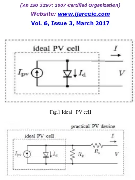
PV cell is a very large area p-n junction diode. The junction between the P and N type material forms the diode. Photons of light falls on the PV cell, it gets directly converted into electrical energy. The energy of photons is used to excite the electrons in the semiconductor material. This transmitted light causes the electrons to move from valence band to the conduction band. When a PV cell is illuminated, The transmitted light generates excess electron-hole pairs , hence the p-n junction is electrically shorted and current will flow .
II. PV MODELLING
Fig.1 Ideal PV cell
Fig 2. Practical PV cell
The output current from the photovoltaic array is
I=I
sc-I
dI
d=I
0(eqvd
/ KT-1)
where Io is the reverse saturation current of the diode, q is the electron charge, Vd is the voltage across the diode, k is Boltzmann constant (1.38 * 10 -19 J/K) and T is the junction temperature in Kelvin (K).
I = Isc – Io (eqVd/kT - 1)
Using suitable approximations,
I = Isc – Io (eq((V+IRs)/nkT) - 1)
I-V CHARACTERISTICS
Fig 3. IV characteristics of PV cell
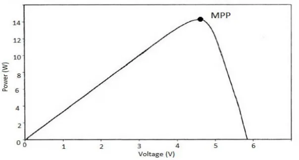
P-V CHARACTERISTICS
Simulation model of PV module
Simulated I-V and P-V characteristics of PV model
Maximum Power Point Tracking Algorithms
Fig5.MPPT Control
Different MPPT techniques
There are different techniques used to track the maximum power point. Few of the most popular techniques are 1) Perturb and Observe (hill climbing method)
2) Incremental Conductance method 3) Fractional short circuit current 4) Fractional open circuit voltage 5) Neural networks
6) Fuzzy logic
The choice of the algorithm depends on the time complexity the algorithm takes to track the MPP, implementation cost and the ease of implementation. Because of less complexity, perturb and observe algorithm and incremental conductance algorithm are selected.
Perturb and Observe (P&O) Algorithm
Fig 6.Flow chart of perturb and observe algorithm
The algorithm is developed in such a manner that it sets a reference voltage of the module corresponding to the peak voltage of the module. A PI controller is used to move the operating point of the module to that particular voltage level. It is observed that there is some power loss due to this perturbation and it also fails to track the power under fast varying atmospheric conditions. But still this algorithm is very popular because of its simplicity.
Incremental Conductance (IC) Algorithm
Fig 7. Flowchart for incremental conductance
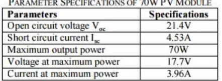
PV Array Characteristics
The mathematical model of PV array is developed using MATLAB Simulink tool box. Various parameters of the PV array are determined and chosen. Series resistance (Rs) is iteratively chosen by incrementing from zero value. Decreasing the value of parallel resistance (Rp) too much will lead ‘Voc’ to decrease and increasing the value of series resistance (Rs) too much will lead ‘Isc’ to drop. ‘Io’ strongly depends on the temperature and hence the simulation circuit of ‘Io’ includes Kv and Ki which are the voltage and current coefficients
.
The light generated by the PV is modeled as an equivalent current source. The series and parallel resistances are connected and simulated. The various equations describing the PV array characteristics are modeled using suitable blocks from the simulink library.
III. SIMULATION MODEL OF P&O ALGORITHM
Fig 8. Simulation model of P&O MPPT with DC to DC converter.
Simulation Model of Incremental Conductance Algorithm
The simulation model of PV array with dc-dc boost converter and InC MPPT algorithm is shown in figure 12, under the same conditions as the P & O algorithm is simulated.
IV. CONCLUSIONS
In this paper a mathematical model of a 70W photovoltaic panel has been developed using MATLAB Simulation. This model is used for the maximum power point tracking algorithms. The P&O and Incremental conductance MPPT algorithms are discussed and their simulation results are presented. It is proved that Incremental conductance method has better performance than P&O algorithm. These algorithms improve the dynamics and steady state performance of the photovoltaic system as well as it improves the efficiency of the dc-dc converter system
.
REFERENCES
[1] D. P. Hohm, M. E. Ropp, “Comparative Study of Maximum Power Point Tracking Algorithms Using an Experimental, Programmable, Maximum Power Point Tracking Test Bed”, 0-7803-5772-8/00,IEEE, 2000, 1699-1702.
[2] N. Pongratananukul and T. Kasparis, “Tool for Automated Simulation of Solar Arrays Using GeneralPurpose Simulators,” in IEEE Conference Proceedings, (0-7803-8502-0/04), 2004, 10-14.
[3]. Zheng Fei; Fei Shu-min; Zhou Xing-peng, "A Novel Maximum-Power-Point Tracking Control Method for Photovoltaic Grid-Connected System," Electrical and ControlEngineering (ICECE), 2010 International Conference on , vol.,no., pp.4920,4923, 25-27 June 2010