Dual-Band Microstrip Filtering Antennas with Symmetrical Slots
Jianfang Deng1, * and Lanping Feng2
Abstract—Two dual-band microstrip antennas with filtering responses are proposed in this letter. By introducing symmetrical slots (One is a U-shaped slot, and the other is an inverted H-shaped slot) at the edge of rectangle patches, additional resonant modes are induced, and both of the antennas have dual operation bands. More importantly, extra radiation nulls are observed between the two bands. In addition, the proposed antennas are fed by microstrip lines with two pairs of symmetrical open stubs, which offer two more radiation nulls at low frequencies. Thus, dual-band filtering responses for the proposed antennas are obtained. Simulated and measured results show good agreements with unidirectional radiation patterns, as well as high selectivity of realized gains.
1. INTRODUCTION
With the rapid developments of wireless communication technology, large number of antennas operating in multiple frequency bands are increasingly demanded [1]. Meanwhile, more and more antennas are integrated together due to the restriction of spaces, which make electromagnetic environments more complicated. In order to improve the selectivity of antennas, filters/duplexers are commonly used in radio frequency (RF) front-ends [2–7]. In conventional filtering antenna designs, stub-loaded resonators, stepped impedance resonators, and cavity filters are mainly integrated into the feedlines. Although the introduction of filters can greatly improve the selectivity of different antennas, filters also consume extra space resources. Besides, the introduction of filters brings extra insertion loss at the same time. To solve this problem, designers tend to use fewer filtering structures and maintain filtering function at the same time [8–10]. Among the filtering antenna designs in recent years, some new techniques are proposed, such as the introduction of shorting pins, stacked patches, and parasitic elements, which mainly concentrate on the radiating performance of different resonant modes for antennas. For example, in [8], a slot coupling technique is introduced into dual-mode patches to generate a good dual-band filtering response. The design of the dual-mode antenna follows the design method for filters. However, with the asymmetry of the antenna structure, the radiation patterns are slightly distorted. In [9], the radiation nulls for the antenna are obtained by introducing a U-shaped slot, three shorting pins, and a stacked patch, and the antenna achieves a good out-of-band gain suppression level of better than 21.5 dB. In [10], two open-ended stubs are introduced as the feedline of the patch antenna, and two radiation nulls are observed. Although the two antennas in [9] and [10] obtain good filtering response, both of them operate at single band. In [11], a dual-band filtering antenna with two pairs of open-stubs and two patches is proposed, and the two working frequencies can be controlled by two open-stubs individually. However, the feeding structure and its coupling with the patch seem to be complicated.
In this letter, simple symmetric slots are introduced into two microstrip antennas to generate additional resonant mode, as well as radiation nulls, and dual operation bands with good filtering responses are obtained. Both of the antennas are simulated, fabricated, and tested. Simulation and measurement results show good agreements.
Received 4 May 2019, Accepted 3 July 2019, Scheduled 21 July 2019
* Corresponding author: Jianfang Deng (demier@163.com).
(a) (b)
Figure 1. Geometry of the proposed antennas. (a) Ant. 1, (b) Ant. 2. The optimized parameters are as follows (unit: mm): a = 60.0, b = 50.0, a1 = 45.0, b1 = 60.0, w = 35.0, w0 = 2.1, w1 = 0.6,
w2 = 16.0, w3 = 2.1, w4 = 0.6, w5 = 35.0, w6 = 30.0, w7 = 2.0, L = 35.0, L0 = 10.0, L1 = 20.5,
L2 = 10.0, L3 = 16.2, L4 = 9.0, L5 = 26.0, L6 = 8.0, L7 = 19.0, L8 = 7.2, L9 = 16.0, L10 = 28.0,
L11= 5.0,L12= 15.0, dw= 0.5,dw1 = 0.5,g1 = 1.6,g2 = 1.0,g3 = 1.3, g4= 1.6,g5 = 0.9,g6= 1.4.
(a) (b)
Figure 2. Simulated|S11|and realized gains with and without slots: (a) Ant. 1, (b) Ant. 2.
2. DESIGN OF THE DUAL-BAND FILTERING ANTENNAS
Figure 1 illustrates the geometry of the two filtering antennas respectively. Both of the microstrip antennas are printed on F4B substrates (εr = 2.65, tanδ = 0.02) with thickness of 0.8 mm. A U-shaped slot is etched at the edge of Ant. 1, and another inverted H-shaped slot is etched at the edge of Ant. 2. The two patches are both fed by microstrip lines with symmetric stepped impedance resonators.
To describe the operation mechanism of the proposed antenna, a comparison of the antenna performance with/without slots is made in Fig. 2. Fig. 2(a) shows the simulated |S11| and realized
gains in the main radiation direction for the two filtering antennas. It can be seen that Ant. 1 operates at a single resonant mode of 2.56 GHz when there is no slot. Besides, two radiation nulls are observed at 2.21 GHz and 2.96 GHz, which are produced by symmetric open-circuited feeding stubs. However, with the U-shaped slot etched at the edge of the radiating patch, Ant. 1 has two resonant modes at 2.36 GHz and 2.54 GHz, respectively. More importantly, three radiation nulls are observed at 2.08 GHz, 2.45 GHz, and 2.82 GHz. Similarly, without the H-shaped slot, Ant. 2 operates at a single resonant mode of 3.16 GHz. However with the slot added, the original resonant mode moves to lower frequencies, and another resonant mode occurs. Meanwhile, an additional radiation null is observed at 2.8 GHz, and a dual-band filtering response is obtained.
(a) (b) (c)
(d) (e) (f)
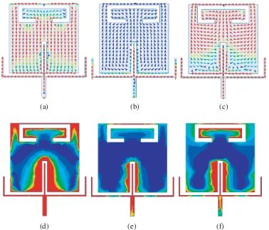
Figure 3. Current distributions and E-fields on Ant. 1: (a) and (d) are for 2.35 GHz, (b) and (e) are for 2.45 GHz, (c) and (f) are for 2.54 GHz.
(a) (b)
Figure 4. S-parameter and realized gain of (a) Ant. 1 change with L5, and (b) Ant. 2 change with
L12. The solid lines are for|S11|, the dotted lines are for realized gains.
E-fields of Ant. 1 are illustrated in Fig. 3. It can be seen that currents that flow along the edge of the patch at 2.35 GHz contribute to the first resonant mode. However, the currents that flow along the slot at 2.54 GHz are symmetric and cancelled out, and the main radiating performance is determined by the currents that flow along the wide side of the patch. Thus, the second resonant mode is obtained. Besides, currents on the patch at 2.45 GHz are extremely week, which contribute to a radiation null in the main radiation direction. Similar conclusions can also be obtained from the analysis ofE-fields.
resonant mode and the additional radiation null are both produced by the slot, it can be seen clearly that the resonant frequency moves to lower frequencies as L5 increases, so does the radiation null. It
can be inferred that as the total length of the slot gets longer, the second resonant mode moves down to lower frequencies. At the same time, the extra radiation null also moves to lower frequencies as the current length of the none resonant frequency gets longer. Fig. 5 shows that the simulatedS-parameter and realized gain of Ant. 2 change with L12. Similar to Ant. 1, as the length of the slot gets longer,
the two resonant modes move to lower frequencies, as well as the extra radiation null. Thus, it can be concluded from Fig. 4 and Fig. 5 that the extra resonant resonant modes and radiation nulls can be individually controlled by tuning the length of the two slots.
Figure 5. Photograph of the two antennas.
(a) (b)
Figure 6. simulated and measuredS-parameters and realized gains for (a) Ant. 1 and (b) Ant. 2.
Table 1.
Ref. Size (λ3) fl/fh (GHz) Radiation nulls configuration
[6] 0.72∗0.72∗0.031 3.6/5.2 3 Dual-mode filter
[8] 0.5∗0.46∗0.018 1.8/2.1 N·G Dual-mode patches
[11] 0.63∗0.5∗0.009 1.9/2.6 4 Multi-stub filter
Ant. 1 0.47∗0.39∗0.006 2.35/2.48 3 Cross stub + slot
3. RESULTS AND DISCUSSION
To validate our design, a prototype of the two antennas are fabricated and measured, as shown in Fig. 5. Fig. 6 demonstrates the simulated and measuredS-parameters and realized gains for the two antennas.
(a) (b)
(c) (d)
Figure 7. Simulated and measured radiation patterns for Ant. 1. (a) and (b) are for 2.35 GHz, (c) and (d) are for 2.54 GHz.
(c) (d)
Figure 8. Simulated and measured radiation patterns for Ant. 2. (a) and (b) are for 2.67 GHz, (c) and (d) are for 3.63 GHz.
Good agreements can be observed between the measured and simulated results. It can be seen that Ant. 1 operates at 2.35 GHz and 2.48 GHz. The realized gains are 5.6 dBi and 5.5 dBi, respectively. Ant. 2 operates at 2.67 GHz and 3.63 GHz, and the realized gains are 5.2 dBi and 5.8 dBi. Besides, excellent dual-band filtering performances are also obtained for both of the antennas. Fig. 7 and Fig. 8 illustrate the simulated and measured radiation patterns for the two antennas. It can be seen that stable and unidirectional radiation patterns with low cross-polarization levels of better than−25 dB are obtained for the two antennas at the resonant frequencies. Besides, a comparison between our antennas and the references is shown in Table 1. It can be seen that the two antennas in our work have more compact sizes with attractive filtering performances compared with the other filtering antennas.
4. CONCLUSION
In our design, two dual-band microstrip patch antennas with filtering responses are proposed. With the introduction of symmetric slots on the patch, higher-order resonant modes, as well as extra radiation nulls, are induced. The second resonant mode and the extra radiation null are mainly determined by the total length of the slot. Besides, the two working frequencies and the extra radiation nulls can be individually controlled by tuning the lengths of the slots. Simulated and measured results both show dual operation bands with filtering responses for the two antennas. Unidirectional radiation patterns with low cross polarization levels are also achieved. Excellent performances of the two antennas make them good candidates for wireless communication systems.
REFERENCES
1. Khan, M. S., M. F. Shafique, A. Naqvi, et al., “A miniaturized dual-band MIMO antenna for WLAN applications,” IEEE Antennas and Wireless Propagation Letters, Vol. 14, 958–961, 2015. 2. Feng, D., H. Zhai, L. Xi, et al., “A new filter antenna using improved stepped impedance hairpin
resonator,” Microwave and Optical Technology Letters, Vol. 59, 2934–2938, 2017.
3. Yao, Y., Z. H. Tu, and Z. Gan, “An integration of dual-band filtering antenna for WLAN application,”IEEE International Conference on Ubiquitous Wireless Broadband, IEEE, 2016. 4. Mao, C. X., S. Gao, Y. Wang, et al., “Compact highly integrated planar duplex antenna for wireless
5. Sahoo, A. K., R. D. Gupta, and M. S. Parihar, “Highly selective integrated filter antenna for UWB application,”Microwave and Optical Technology Letters, Vol. 59, 1032–1037, 2017.
6. Mao, C. X., S. Gao, Y. Wang, et al., “Dual-band patch antenna with filtering performance and harmonic suppression,”IEEE Transactions on Antennas &Propagation, Vol. 64, 4074–4077, 2016. 7. Mansour, G., M. J. Lancaster, P. S. Hall, P. Gardner, and E. Nugoolcharoenlap, “Design of filtering microstrip antenna using filter synthesis approach,”Progress In Electromagnetics Research, Vol. 145, 59–67, 2014.
8. Ogbodo, E. A., M. G. Aly, A. E. Ali, Y. Wu, and Y. Wang, “Dual-band filtering antenna using dual-mode patch resonators,”Microwave and Optical Technology Letters, Vol. 60, 2564–2569, 2018. 9. Zhang, X. Y., W. Duan, and Y. M. Pan, “High-gain filtering patch antenna without extra circuit,”
IEEE Transactions on Antennas& Propagation, Vol. 63, 5883–5888, 2017.