Omnidirectional Compact Dual-Band Antenna Based on
Dual-Frequency Unequal Split Ring Resonators
for WLAN and WiMAX Applications
Patricia Castillo-Aran´ıbar1, 2, *,
Alejandro Garc´ıa-Lamp´erez2, and Daniel Segovia-Vargas2
Abstract—An omnidirectional compact antenna based on dual-band Split Ring Resonators (SRRs) for 2.45 GHz wireless local area network (WLAN) and 3.5 GHz worldwide interoperability for microwave access (WiMAX) applications is presented. Different and new properties of SRRs, such as dual-band or multi-band performance in the design of compact antennas, can be obtained by making the rings unequal and asymmetric. The dual-band SRR antenna is designed with a bandwidth control technique based on the stored electromagnetic energy in the resonator rings. The obtained results show that the SRR antenna has good omnidirectional radiation pattern for both bands and good impedance bandwidth. In addition, compactness and flexibility are obtained with a simple structure of the SRRs.
1. INTRODUCTION
The fast development in wireless communication systems integrating more than one service into one system has increased the use of multi-band antenna technology. Multi-band antennas have been proposed for WLAN and WiMAX applications with compact characteristics and omnidirectional radiation pattern to provide the full coverage needed for wireless connections. A dual-band monopole antenna with a microstrip feeding and a short stem with two branches is proposed in [1]. A printed slot antenna with an inverted-L slot generates two resonant modes for dual-band operations [2] and three resonant modes for a triple-band operations [3]. Similarly, compact tri-band antennas are proposed in [4, 5] and [6] by modifying the radiators with different geometric shapes. A 50 Ω microstrip line loaded with a dumbbell-shaped defected microstrip structure for resonances with two shorted vias to create additional resonances in [7]. By introducing meandered strips on a ring monopole antenna, a dual-band response is generated in [8–10]. A compact dual-band/triple-band rupee-shaped coplanar waveguide (CPW) fed monopole antenna is obtained in [11]. All of the previous reported designs have more or less complex and more or less miniaturized structures to cover WLAN/WiMAX operating bands. However, nowadays, in the coming period of internet of things (IoT), the need of having more and more compact and flexible omnidirectional antenna structures that can reach any corner is transforming the need of having miniaturized, flexible omnidirectional antennas into a real must.
Lately, concerning their size and application, several dual-band (or even triple-band) antennas with omnidirectional pattern have been designed for wireless applications, specifically, for 2.45 GHz (WLAN) and 3.5 GHz (WiMAX) applications. Between the proposed compact antennas, a dual-band monopole with a short stem and two branches with an antenna size of 40×35 mm2 (although the overall dimension of the radiator was 14.5×8.7 mm2) is mentioned in [1]. A triple band monopole with a toothbrush-shaped patch, a meander line and an inverted U-shaped patch with a size of 30×20 mm2
Received 22 May 2017, Accepted 27 August 2017, Scheduled 15 April 2018 * Corresponding author: Patricia Castillo-Aran´ıbar ([email protected]).
is presented in [6]. A compact dual-band/triple-band rupee-shaped coplanar waveguide (CPW) fed monopole antenna with a size of 17.5×17.5 mm2 is obtained in [11]. In [9] a compact asymmetric
coplanar strip-fed printed monopole dual-band antenna with an arc-shaped strip and an omega-shaped strip has a size of 18×22 mm2. A printed coaxial cable feeding with size of 45×12 mm2 is shown in [12]
and 50.2×19.2 mm2 in [13]. A coplanar waveguide (CPW)-fed monopole with a size of 28×33 mm2 is presented in [14] and a microstrip line loaded with a dumbbell-shaped defected microstrip structure with size 40×10 mm2 in [7]. All these multi-band antennas are designed with resonators of different geometric shapes.
The fact that SRRs can have dual-frequency performance while keeping their miniaturization degree can offer new possibilities to design miniaturized, omnidirectional and bandwidth controlled antennas at their corresponding resonant frequencies. Multi-band performance with asymmetric bandwidths can be achieved by controlling the resonant frequencies and their respective bandwidths through the SRR behavior related to the number of rings and the coupling between them. Traditionally, the performance of SRRs was restricted to only one frequency. However, it has been shown [15] that SRRs present two different frequencies when an appropriate design is undertaken.
The basic structure of the proposed antenna is SRR, composed of several (at least 2) concentric conductive open rings with gaps placed at opposite positions. Open loops are used to reduce the antenna size (thanks to their reduced footprint), achieved due to the fundamental resonance occurring at frequencies much lower than that of only one open-loop resonator with the same dimensions (sub-wavelength effect) [16]. When the surface of the SRR is exposed to a perpendicular magnetic field, currents are induced in the rings, and they are able to pass from one ring to another [17]. The use of SRRs offers flexibility to the design, since the required frequency bands can be chosen with a simple structure. A novel use of the ring resonators is given in this work by using the multi-resonant property of the SRRs besides the typical miniaturization characteristic of the SRRs [18].
A different and novel property of the SRRs is used in this work. The existence of a potential asymmetry (by designing unequal rings) between the coupled rings in the SRR allows achieving multi-frequency performance of the SRR. This property allows having a novel, up to the authors’ knowledge, design of an antenna made of unequal SRRs, which provides a compact, omnidirectional, miniaturized and flexible antenna able to provide suitable coverage for new services such as IoT. This antenna will also provide easiness for device integration. Good return loss and radiation pattern characteristics are obtained in the frequency band of interest.
The paper is organized as follows. The first section describes the introduction of the paper. The second section introduces the analysis and performance of the SRR. The third section provides the design of the SRR antenna while the next section provides the simulation and measurement results of the miniaturized omnidirectional. Finally, last section presents the conclusions.
2. SRR DESIGN
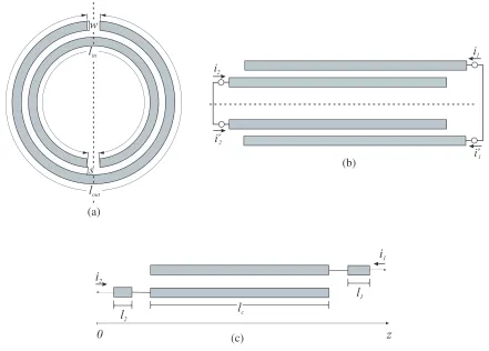
The SRR design with bandwidth control technique is applied to a resonator of unequal rings (Fig. 1(a)). An explanation is given below in order to obtain a dual-band response while controlling their resonance bandwidths. As the resonator is the basic structure of a radiator, the bandwidth control will remain in the frequency response of the antenna.
The SRR is represented by coupled transmission line with different lengths (Fig. 1(b)). Considering the symmetry of the proposed structure, only one half resonator is analysed. The half resonator model is obtained by splitting the resonator along a symmetry plane, represented by the dotted line in Fig. 1(a). The half resonator is composed of a section of two-conductor transmission lossless lines with different lengths (see Fig. 1(b)). The analysis consists in separating the coupled transmission lines into subsections connected in cascade: two single line sections of lengths l1 and l2, and a coupled line section of length
lc, as can be seen in Fig. 1(c).
Each sub-section is represented by an open circuit impedance matrixZshown in Eq. (1) [16].
Z(θ) = vp
jsinθ
cosθL L L cosθL
i2
i’2
i1
i’1
351,07°
lout
348.07° 351,07°
lin w
6.53
s
5.00
lc
l1 l2
i2
i1
z 0
(a)
(b)
(c)
Figure 1. Structure of a split ring resonator. (a) Layout. (b) Sections of dual-conductor transmission line, dotted lines represent the symmetry plane. (c) Half resonator model into sub-sections.
This model is considered lossless, thus R and Gare dismissed, so the reactive parameters Land C are used. If C is chosen, the voltage distribution of the half model has to be used. L is a 1×1 matrix for the single line sections, and L is a 2×2 matrix for the coupled line section. For the later case, Eq. (1) is modified to represent the open end terminals by eliminating the rows and columns at the respective open ends positions [16]. Z is related to the voltages and currents at the symmetry plane (Fig. 1(b)) and expressed in terms of the primary parameter (inductance per-unit-length) of each transmission line section. The impedance matrix of the half resonator Zis obtained by connecting in cascade the impedance matrices of all the subsections.
The resonant frequencies of the half resonator are represented by the nontrivial solutions ofZi= 0. This equation results from analysing the vector of voltages at the symmetry plane asZi=Zi, wherei andi are the vectors of currents going into each half resonator through the symmetry plane, considering that the currents are i1 = −i1 and i2 = −i2 (see Fig. 1(b)) going into the other half resonator [16].
At resonant conditions, the currents that cross the symmetry plane are represented by the eigenvectors corresponding to the zero eigenvalue of the singular matrixZ. Thus, the current distribution along the rings of the resonator can be obtained.
The current distribution of the first conductor of the half resonator is
i1(z) =
⎧ ⎪ ⎪ ⎪ ⎪ ⎨ ⎪ ⎪ ⎪ ⎪ ⎩
i1(0) sinβ(l1−z) +i1(l1) sinβz
sinβl1
z∈[0, l1]
i1(l1) sinβ(lc+l1−z)
sinβ(lc) z∈[l1, lc+l1]
0 z∈[lc+l1, l2+lc+l1]
while for the second conductor the current distribution is
i2(z) =
⎧ ⎪ ⎪ ⎪ ⎪ ⎪ ⎨ ⎪ ⎪ ⎪ ⎪ ⎪ ⎩
0 z∈[0, l1]
i2(lc) sinβ(z−l1)
sinβ(lc) z∈[l1, l1+lc],
i2(lc) sinβ(l1+lc+l2−z) +i2(l2) sinβ(z−lc−l1)
sinβ(l2)
z∈[l1+lc, l1+lc+l2]
(3)
whereβ =ω/vp is the phase constant.
The applied technique to control the resonant bandwidths uses a bandwidth ratio (BWR), defined as the quotient between the second and first resonances,
BWR Δω2 Δω1
= Wm(ω01)
Wm(ω02)
. (4)
where Δω2 and Δω1 are the bandwidths of the second and first resonances, andWm(ω01) andWm(ω02)
are the stored magnetic energies at both resonances.
Both ratios Δω2/Δω1 and Wm(ω01)/Wm(ω02) are related through the external quality factor Qe.
Considering that the power delivered to the input impedance of the resonator is constant at every resonance, this value is dismissed at the time to calculate BWR.
The stored magnetic energy for each sub-section is calculated in terms of the obtained current distribution of the half resonator as in [19].
In the case of the half resonator, the magnetic stored energy is the sum of the calculated energies of each subsection,
Wm=WmA+WmB+WmC (5) whereWmA and WmC are the energies corresponding to simple transmission lines,
WmA= 1 2
l1
0
Li21(z)dz (6) and
WmC = 1 2
l1+lc+l2
l1+lc
Li22(z)dz (7)
whereLis the distributed inductances of each single line, andi2
1(z) andi22(z) are the current distributions
of each conductor.
WhileWmB is the energy of the section of coupled lines,
WmB= 1 2
l1+lc
l1
L11(z)i21(z) + 2L12i1(z)i2(z) +L22(z)i22(z)dz. (8)
whereL11,L12 and L22 are the elements of the matrix of distributed inductanceL.
For the whole resonator, the computed energy is doubled due to the symmetry. However, as the BWR is just the quotient of energies, Equation (5) can be directly applied in Eq. (4).
2.1. SRR Geometry
The BWR specifications for the designed SRR of the proposed antenna are 2 : 1, and for WLAN and WiMax applications, the chosen resonances are 2.45 and 3.5 GHz, respectively. The SRR is designed on a Rogers RO3010 substrate with a dielectric constant of 10.2 and thickness of 0.64 mm.
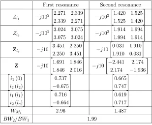
Table 1. Impedance parameters of the SRR.
First resonance Second resonance
Zl1 −j102 2.271 2.339
2.339 2.271
−j102 1.420 1.525
1.525 1.420
Zl2 −j102 3.024 3.075 3.075 3.024
−j102 1.914 1.994 1.994 1.914
Zlc −j10 3.451 2.250 2.250 3.451
−j10 0.031 1.910 1.910 0.031
Z −j10 1.691 1.846 1.846 2.016
−j10 −2.441 2.174 2.174 −1.936
i1(0)
i2(l2)
0.737
−0.675
0.665 0.747
i1(l1)
i2(lc)
0.716
−0.664
0.619 0.717
WM1 2.96 1.487
BW2/BW1 1.99
resonances, the first resonant bandwidth is approximately 50% of the second one. These results are also shown in Table 1.
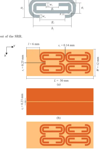
An electromagnetic simulation of the SRR is performed using Ansys HFSS software to confirm these results. The eigenmode solution is used to get the two resonances of the structure, which are at 2.44 and 3.5 GHz. The first resonance is slightly higher than the one obtained in the proposed method, but still with satisfactory results, which confirm the behaviour of the SRR. The resonators will be placed together in order to use them as the radiator of the proposed antenna. Detailed dimensions of the SRR can be seen in Fig. 2 as follows: ao = 4.64 mm, bo = 11.61 mm, ai = 2.57 mm, bi = 9.40 mm,
go = 6.2 mm, gi = 3.1 mm, s= 0.33 mm, wi = 0.8 mm, wo = 0.77 mm. Note that wi is sightly greater thanwo.
3. ANTENNA DESIGN
A single SRR with a dual conductor transmission line of different lengths was designed in the previous section, the bandwidth of the resonances are determined by given specifications BWR 2 : 1. Eight SRRs are used as a radiator, four resonators on each side are coupled between them.
The antenna is fed through a slot-line between the layers. The resonators are excited by an enhanced magnetic axial field generated by the slot-line. Finally, the design procedure can be summarised as follows
1. Design the SRR in order to have dual-band performance.
2. Design a feeding structure (slot line) in order to couple the axial magnetic field. 3. Design the array of coupled SRR.
gi
wo go
ao ai
bo
bi
0.77 mm
0.80 mm
11.61 mm
wi
4.64 mm4.64 mm
6.20 mm
0.33 mm
2.57 mm
3.10 mm
s
9.40 mm
Figure 2. Layout of the SRR.
W
= 12 mm
L = 30 mm
l = 6 mm s = 0.14 mm
1
s
= 0.25 mmr
0.23 mm
s
= 0.23 mmf
12.18 mm
30.61 mm 6.05 mm 0.14 mm
0.25 mm
X Y
(a)
(b)
(c)
Figure 3. Antenna geometry of the proposed design. (a) Top layer. (b) Slot stripline layer. (c) Bottom layer.
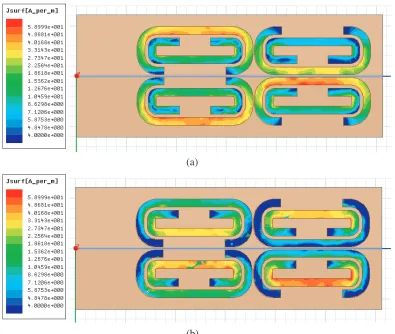
(a)
(b)
Figure 4. Surface current distribution of the dual-band antenna. (a) 2.45 GHz, (b) 3.5 GHz.
4. RESULTS AND DISCUSSIONS
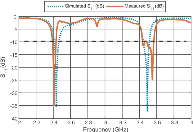
Based on the design results, a prototype of the SRR antenna is manufactured as shown in Fig. 5. The proposed antenna was built as a hand crafted prototype, joining two substrates, with four coupled resonators at the top and four coupled resonators at the bottom of the structure. An SMA conductor was welded in between the layers, instant adhesive glue was used to join the layers, and the frequency response of the antenna is not affected by the glue. It has a compact size of 30×12 mm2. The two resonances are slightly shifted from the simulated results.
The proposed antenna of this work is a compact planar antenna based on split ring resonators fed through a slot-line with omnidirectional radiation, reasonably small size, and a bandwidth control of the resonances to ensure the efficient use of the frequency range. The return losses of the antenna are measured with a VNA (Anritsu MS2027C), and the radiation pattern and gain are measured in a Stargate64 (SG64 from MVG).
(a)
(b)
(c)
Figure 5. Manufactured antenna based on SRR. (a) Top side. (b) Middle side. (c) Bottom side.
Frequency (GHz)
2 2.2 2.4 2.6 2.8 3 3.2 3.4 3.6 3.8 4
S 11
(dB)
-40 -35 -30 -25 -20 -15 -10 -5 0
Simulated S
1 1(dB) Measured S1 1(dB)
-30 -20 -10 0 0° 30° 60° 90° 120° 150° 180° 210° 240° 270° 300° 330° Simulated Measured -30 -20 -10 0 0° 30° 60° 90° 120° 150° 180° 210° 240° 270° 300° 330° -30 -20 -10 0 0° 30° 60° 90° 120° 150° 180° 210° 240° 270° 300° 330° 0° 30° 60° 90° 120° 150° 180° 210° 240° 270° 300° 330° -30 -20 -10 0 y-z plane y-z plane x-z plane x-z plane (a) (b)
Figure 7. Simulated and measured radiation pattern of the proposed antenna. (a) First resonant frequency. (b) Second resonant frequency.
Frequency (GHz)
2.38 2.42 2.46 3.46 3.5 3.54 3.58
Gain (dB) -7 -6 -5 -4 -3 Measured Simulated
measured patterns are similar to the simulated ones at thex-z plane. The discrepancy at 0◦ in they-z
plane is due to the non-perfect fastening of the antenna to the measurement setup. As shown in Fig. 8, the measured and simulated peak antenna gains for the proposed antenna are also in good agreement. These gains are around−5 dB for the lower operating band and−4.6 dB for the upper one.
The main goal of the paper is to use a novel element that can have two or more independent resonances which can be controlled by means of the coupling between the corresponding lines of only one SRR. The SRR used to compose the proposed antenna has a number of resonances depending on the number of rings of the SRR. These resonances show a highQ-factor. In this paper, four resonators (by side) are used to form the radiator but with small gain. In addition, there is a tradeoff between some design parameters, in this case the gain and the size, i.e., it is possible to obtain higher gain by increasing the number of resonators, but it will increase the size of the antenna, which is one of the attributes of this prototype. At the time to design a microwave structure, there is always a tradeoff between the obtained results and the specifications. While a good miniaturization and flexibility are obtained, some antenna parameters are decreased, and in this case the total measured gain that for both resonant frequencies is small, but the obtained values are admissible for the proposed applications as the power in the receiver is low in some wireless applications, thus, these values are acceptable. It is possible to increase the gain by adding more resonators to each side of the radiator, but the compactness of the proposed antenna will be lost.
5. CONCLUSIONS
A dual-band antenna based on SRRs and fed through a slot-line has been designed and manufactured in this paper. The dual-band response comes from the two resonances of the designed SRRs. One of the goals was the control of the resonant bandwidths. To get it, a previous resonator was designed with a bandwidth control technique based on the bandwidth ratio BWR which relates the resonances bandwidths and the the stored electromagnetic energy on the conductors of the proposed model. Mathematical analysis is given about this relation in this work. The main advantage of the proposed design procedure is that the antenna performance can be controlled and fixed by modifying the coupling between different resonators forming the antenna and the gaps of the rings at the SRR design stage. The proposed control bandwidth technique previously defines the ratio between the bandwidths of the resonances of the SRR. It is shown that this bandwidth control is maintained in the applications, in this case the designed antenna. With this proposed design is possible to establish a relation between the operating bands of the antenna in the design of its basic structure (SRR). The designed dual-band antenna shows two resonances, and the specification was to define the higher resonance bandwidth to be twice wider than the lower one. The antenna shows an omnidirectional radiation at both resonances and has a compact size of 30×12 mm2. It also shows good radiation characteristics. It has been
demonstrated that the defined bandwidth ratio of the dual-band frequency responses is provided by the length of the rings and the coupling between resonators. It has been shown that the characteristics of realized antenna have good agreements with the proposed design. The design method could be extended to multi-frequency antennas, at least triple band antennas, by adding more coupled rings to the SRR.
ACKNOWLEDGMENT
The measurements of this work were realized in the equipment Startgate64 funded by the National Innovation Program for Competitiveness and Productivity — Inn´ovate Per´u, according to agreement No. 014-PNICP-EC-2015.
REFERENCES
1. Sun, X. L., W. S. W. Cheung, and T. I. Yuk, “Compact dual-band monopole antenna for 2.4/3.5 GHz WiMAX applications,” PIERS Proceedings, 487–489, Taipei, March 25–28, 2013. 2. Lee, Y.-C. and J.-S. Sun, “Compact printed slot antennas for wireless dual- and multi-band
3. Verma, S. and P. Kumar, “Compact triple-band antenna for WiMAX and WLAN applications,” Electronics Letters, Vol. 50, No. 7, 484–486, March 2014.
4. Wu, T., X.-W. Shi, P. Li, and H. Bai, ‘Tri-band microstrip-fed monopole antenna with dualpolarisation characteristics for WLAN and WiMAX applications,”Electronics Letters, Vol. 49, No. 25, 1597–1598, December 2013.
5. Hoang, T. V. and H. C. Park, “Very simple 2.45/3.5/5.8 GHz triple-band circularly polarised printed monopole antenna with bandwidth enhancement,”Electronics Letters, Vol. 50, No. 24, 1792–1793, 2014.
6. Li, Y. and W. Yu, “A miniaturized triple band monopole antenna for WLAN and WiMAX applications,” International Journal of Antennas and Propagation, Vol. 2015, article ID 146780, 2015.
7. Malik, J., A. Patnaik, and M. V. Kartikeyan, “A compact dual-band antenna with omnidirectional radiation pattern,” IEEE Antennas and Wireless Propagation Letters, Vol. 14, 503–506, 2015. 8. Zhao, G., F.-S. Zhang, Y. Song, Z.-B. Weng, and Y.-C. Jiao, “Compact ring monopole antenna with
double meander lines for 2.4–5 GHz dual-band operation,”Progress In Electromagnetics Research, Vol. 72, 187–194, 2007.
9. Naidu, P. V. and R. Kumar, “Design of a compact ACS-fed dual band antenna for bluetooth/WLAN and WiMAX applications,” Progress In Electromagnetics Research C, Vol. 55, 63–72, 2014. 10. Sze, J. Y., T. H. Hu, and T. J. Chen, “Compact dual-band annular-ring slot antenna with
meandered grounded strip,” Progress In Electromagnetics Research, Vol. 95, 299–308, 2009. 11. Naidu, V. P. and R. Kumar, “Design of compact dual-band/tri-band CPW-fed monopole antennas
for WLAN/WiMAX applications,” Wireless Personal Communications, Vol. 82, No. 1, 267–282, May 2015, [Online], Available: http://dx.doi.org/10.1007/s11277-014-2207-z.
12. Zhang, Z., M. F. Iskander, J. C. Langer, and J. Mathews, “Dual-band WLAN dipole antenna using an internal matching circuit,” IEEE Transactions on Antennas and Propagation, Vol. 53, No. 5, 1813–1818, May 2005.
13. Lizzi, L., F. Viani, and A. Massa, “Dual-band spline-shaped PCB antenna for wi-Fi applications,” IEEE Antennas and Wireless Propagation Letters, Vol. 8, 616–619, 2009.
14. Chu, Q. X. and L. H. Ye, “Design of compact dual-wideband antenna with assembled monopoles,” IEEE Transactions on Antennas and Propagation, Vol. 58, No. 12, 4063–4066, December 2010. 15. Geschke, R. H., B. Jokanovic, and P. Meyer, “Compact triple-band resonators using multiple
split-ring resonators,” 2009 European Microwave Conference (EuMC), 366–369, September 2009. 16. Garc´ıa-Lamp´erez, A. and M. Salazar-Palma, “Dual band filter with split-ring resonators,” 2006
IEEE MTT-S International Microwave Symposium Digest, 519–522, June 2006.
17. Baena, J. D., J. Bonache, F. Martin, R. M. Sillero, F. Falcone, T. Lopetegi, M. A. G. Laso, J. Garcia-Garcia, I. Gil, M. F. Portillo, and M. Sorolla, “Equivalent-circuit models for split-ring resonators and complementary split-ring resonators coupled to planar transmission lines,” IEEE Transactions on Microwave Theory and Techniques, Vol. 53, No. 4, 1451–1461, April 2005.
18. Mrabet, O. E., M. Aznabet, F. Falcone, M. Essaaidi, and M. Sorolla, “A compact antenna based on split ring resonator,”Proceedings of the Fourth European Conference on Antennas and Propagation, 1–3, April 2010.