Available online: https://edupediapublications.org/journals/index.php/IJR/ P a g e | 3484
Design and Finite Element Analysis of Vertical Pressure Vessels
Subjected To Applied Forces
Patancheru Shiva& Mr. K.Bicha
1
M.Tech In Machine Design From Malla Reddy College Of Engineering And Technology, Jntu, Hyderabad, Telangana, India
2
Assistant Professor, Malla Reddy College Of Engineering And Technology, Jntu, Hyderabad, Telangana, India
ABSTRACT
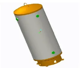
Vertical pressure vessels consist of a cylindrical shell and dished bottoms. They are placed on three welded legs. The size and positioning of the filler necks is adjusted according to the customer requirements and accordance with the relevant European standards. The pressure vessels can be produced from ferrous or austenitic steel.In this thesis, a vertical pressure vessel is designed subjected to different loads internal pressure and external pressure by theoretical calculations. The models are done in Creo 2.0.Static, Modal and Random vibration analysis are done on the model to determine displacements, stresses, frequencies, directional deformations and shear stresses. Analysis will be done in Ansys 14.5.
INTRODUCTION TO PRESSURE
VESSEL
A pressure vessel is a closed container designed to hold gases or liquids at a pressure substantially different from the ambient pressure.Cylinders are widely used for storage due to their being less expensive to produce than spheres. However, cylinders are not as strong as spheres due to the weak point at each end.This weakness is reduced by hemispherical or rounded ends being
fitted. If the whole cylinder is manufactured from thicker material than a comparable spherical vessel of similar capacity, storage pressure can be similar to that of a sphere.Main pressure vessel components
1.Shell, 2.head, 3.nozzle, 4.supports, 5.saddle supports, 6.leg supports, 7.lug supports, 8. Skirt supports
LITERATURE REVIEW
In the paper by Mane S.S[1], deals with
International Journal of Research
Available at https://edupediapublications.org/journals
e-ISSN: 2348-6848 p-ISSN: 2348-795X Volume 04 Issue-17 December 2017
Available online: https://edupediapublications.org/journals/index.php/IJR/ P a g e | 3485
investigating vibration possibilities in
vertical pressure vessels.In the paper by V.
P. Gawade [2], The pressure vessel is designed for internal pressure using ASME Codes. The components of the pressure vessel are designed by calculating the factors like thickness of the shell, head, stress analysis etc. To validate the design result the pressure vessel is modeled and analyzed in ANSYS. The preferred method to conduct the analysis is FEA. In the paper by A. DEVARAJU [3], The main objective of this paper is to design the standard cylindrical pressure vessel and calculate the stresses induced in the various part of the vessel by manually and compare these results with the ANSYS results.
Pressure Calculations of Pressure vessel for internal forces
(𝒕𝒓) = 𝑃𝑅𝑖 / (SE-0.6P)
Where
Internal design pressure = p
Maximum allowable stress value = S Weld joint efficiency = 1
Corrosion allowance = C.A = 1.5 Total shell thickness = tr+ C.A Total shell thickness = 50.8
𝒕𝒓 = 𝑃𝑅𝑖 / (SE-0.6P)
Pressure Calculations of Pressure vessel for external forces
r = 𝑊𝑒1
𝑊𝑒
r = n2−1
n2−1+m
m = 𝜋2R2/2L2
𝑆𝑏= 4𝑊𝑒
𝜋𝐷2𝑡
𝑆𝑏= 4𝑀
𝜋𝐷2𝑡
Where,
M = bending moment due to horizontal loads
n = number of lobes into which shell may buckle
We1= collapsing pressure for external
pressure acting on sides and Ends of vessel, psi
We= collapsing pressure for external pressure acting on sides of
Vessel only, psi
R = outside radius of shell
Sb = bending stress on outermost fiber, psi
BOUNDARY CONDITIONS
The reference journal for modeling and analysis are taken from following journal
―The Design Of Vertical Pressure Vessels
Subjected To Applied Forces And
Vibrational Conditions by Maane S.S, Prof. Wankhede P.A‖ specified as [1] in
References chapter.
Fig – Assembly of vertical pressure vessel
ANALYSIS OF VERTICAL
PRESSURE VESSELS
MATERIAL - HIGH CARBON STEEL
STATIC STRUCTURAL, MODAL AND RANDOM VIBRATION ANALYSIS
Available online: https://edupediapublications.org/journals/index.php/IJR/ P a g e | 3486
Fig: Imported Geometry of Vertical Pressure Vessel
Fig: Meshed model of Vertical Pressure Vessel
Fig: Fixed support applied at bottom of vessel
Fig: Pressure is applied insidevessel
Fig: Total deformation of Vertical Pressure Vessel using High Carbon Steel by applying
internal pressure
Fig: Stress of Vertical Pressure Vessels using High Carbon Steel by applying
International Journal of Research
Available at https://edupediapublications.org/journals
e-ISSN: 2348-6848 p-ISSN: 2348-795X Volume 04 Issue-17 December 2017
Available online: https://edupediapublications.org/journals/index.php/IJR/ P a g e | 3487
Fig: Strain of Vertical Pressure Vessels using High Carbon Steel by applying
internal pressure
Fig: Mode-1 of Vertical Pressure Vessels using High Carbon Steel by applying
internal pressure
Fig: Mode-2 of Vertical Pressure Vessels using High Carbon Steel by applying
internal pressure
Fig: Mode-3 of Vertical Pressure Vessels using High Carbon Steel by applying
internal pressure
Fig: Directional Deformation of Vertical Pressure Vessels using High Carbon Steel
Available online: https://edupediapublications.org/journals/index.php/IJR/ P a g e | 3488
Fig: Shear Stress of Vertical Pressure Vessels using High Carbon Steel by applying
internal pressure
Fig: Shear Elastic Strain of Vertical Pressure Vessels using High Carbon Steel by
applying internal pressure
BY APPLYING INTERNAL & EXTERNAL PRESSURES
Fig: Pressure is applied internally and externally on the Pressure Vessel
Fig: Total deformation of Vertical Pressure Vessel using High Carbon Steel by applying
International Journal of Research
Available at https://edupediapublications.org/journals
e-ISSN: 2348-6848 p-ISSN: 2348-795X Volume 04 Issue-17 December 2017
Available online: https://edupediapublications.org/journals/index.php/IJR/ P a g e | 3489
Fig: Stress of Vertical Pressure Vessels using High Carbon Steel by applying
internal & external pressure
Fig: Strain of Vertical Pressure Vessels using High Carbon Steel by applying
internal & external pressure
Fig: Mode-1 of Vertical Pressure Vessels using High Carbon Steelby applying internal &
external pressure
Fig: Mode-2 of Vertical Pressure Vessels using High Carbon Steelby applying internal &
external pressure
Fig: Mode-3 of Vertical Pressure Vessels using High Carbon Steelby applying internal &
external pressure
Fig: Directional Deformation Vertical Pressure Vessels using High Carbon Steelby applying
Available online: https://edupediapublications.org/journals/index.php/IJR/ P a g e | 3490
Fig: Shear Stress of Vertical Pressure Vessels using High Carbon Steelby applying internal
& external pressure Vessels using High Carbon SteelFig: Shear Elastic Strain of Vertical Pressure by applying
internal & external pressure
GRAPHS FOR COMPARISION OF RESULTS OF INTERNAL, INTERNAL&EXTERNAL PRESSURES
475 480 485 490 495 500 505 510
High carbon steel
Austenitic Stainless
Steel
Alloy Steel(A36)
STRESS
(MPa)
MATERIALS
COMPARISON OF STRESS VALUES FOR DIFFERENT MATERIALS OF INTERNAL, INTERNAL&EXTERNAL
PRESSURES
Internal
International Journal of Research
Available at https://edupediapublications.org/journals
e-ISSN: 2348-6848 p-ISSN: 2348-795X Volume 04 Issue-17 December 2017
Available online: https://edupediapublications.org/journals/index.php/IJR/ P a g e | 3491
CONCLUSION
By observing static structural analysis results, the stresses are reducing for internal + external pressures. The stresses are decreasing by applying internal + external pressures by about 2.282% for High Carbon
Steel, by about 2.08% for Austenitic Stainless Steel and by about 1.1% for Alloy Steel when compared with by applying internal pressures.By observing modal analysis results, the frequencies are slightly increasing when internal + external pressures are applied than applying internal
228 230 232 234 236 238 240 242 High carbon steel Austenitic Stainless Steel Alloy Steel(A36) FREQUENC Y(HZ) MATERIALS
COMPARISON OF FREQUENCY VALUES FOR DIFFERENT MATERIALS OF INTERNAL, INTERNAL&EXTERNAL
PRESSURES Internal Internal&External 2600 2700 2800 2900 3000 3100 High carbon steel Austenitic Stainless Steel Alloy Steel(A36) SHE AR STRESS(Mpa) MATERIALS
COMPARISON OF SHEAR STRESS VALUES FOR DIFFERENT MATERIALS OF INTERNAL, INTERNAL&EXTERNAL
PRESSURES
Internal
Available online: https://edupediapublications.org/journals/index.php/IJR/ P a g e | 3492
pressures.By observing Random Vibration analysis results, the shear stresses are reducing for internal + external pressures. The stresses are decreasing by applying internal + external pressures by about 4.08% for High Carbon Steel, by about 3.41% for Austenitic Stainless Steel and by about 1.19% for Alloy Steel when compared with by applying internal pressures.
REFERENCES
[1],ManeS.SThe Design Of Vertical
Pressure Vessels Subjected To Applied Forces And Vibrational Conditions
[2], V. P. Gawade Design & Analysis of Vertical Pressure Vessel by using ASME Codes
[3], JAGAJYOTI PANDA Analysis And Design Of Vertical Vessel Foundation,
[4], Dhaval A Static and Dynamic Analysis
of Pressure Vessel with Vertical orientation using PVElite
[5], HemantBhosale [6], Design of Vertical Pressure Vessel using PV Elite software,
[6]A. DEVARAJU A Study On Stress Analysis For Design Of Pressure Vessel
[7] V.B. Bhandari, ―Design of Machine Elements‖, Tata McGraw Hill Publishing Co. Ltd, New Delhi, 2005 [8] British Standard Specification for Design & manufacture of water tubes, steam generating plants (including superheaters, reheaters& steel tube economizers) : BS 1113, 2011
[9] Indian Standard- Hot Rolled Medium And High Tensile Structural Steel — Specification- BIS- 2011
[10] D. Gandy, ―Carbon Steel handbook‖,
Electric Research Power Institute,