Electronic Thesis and Dissertation Repository
12-14-2015 12:00 AM
Slope Stability Enhancement of an Upstream Tailings Dam:
Slope Stability Enhancement of an Upstream Tailings Dam:
Laboratory Testing and Numerical Modelling
Laboratory Testing and Numerical Modelling
Yazeed A. Alsharedah
The University of Western Ontario
Supervisor
Prof. M. Hesham El-Naggar The University of Western Ontario
Graduate Program in Civil and Environmental Engineering
A thesis submitted in partial fulfillment of the requirements for the degree in Master of Engineering Science
© Yazeed A. Alsharedah 2015
Follow this and additional works at: https://ir.lib.uwo.ca/etd
Part of the Civil Engineering Commons, Computational Engineering Commons, Construction Engineering and Management Commons, Environmental Engineering Commons, Geotechnical Engineering Commons, and the Polymer Science Commons
Recommended Citation Recommended Citation
Alsharedah, Yazeed A., "Slope Stability Enhancement of an Upstream Tailings Dam: Laboratory Testing and Numerical Modelling" (2015). Electronic Thesis and Dissertation Repository. 3480.
https://ir.lib.uwo.ca/etd/3480
This Dissertation/Thesis is brought to you for free and open access by Scholarship@Western. It has been accepted for inclusion in Electronic Thesis and Dissertation Repository by an authorized administrator of
i
Mine tailings are the byproduct of mining activities, which need to be disposed of once the
ore is extracted. They can be disposed of in either dry or wet forms. The latter is most common
with the tailings being disposed of in the form of slurry inside retention structures. The retention
structure may be a natural, manmade, or built dam, which is the case in most current mining
locations. In this thesis, improving the stability of an upstream tailings dam using soil additives
is investigated. The experimental phase of this study involved laboratory tests conducted to
characterize mine tailings and to investigate any change in their properties upon stabilization
with non-traditional and traditional additives; namely, emulsified polymer and a mixture
composed of Cement Kiln Dust, CKD, and re-cycled Gypsum. Afterwards, the soil modified
parameters are used to establish a finite element model employing the commercial code PLAXIS
2D to simulate the behavior of the improved soil when a tailings dam is formed. The numerical
model demonstrated that utilizing a CKD: B mix increased the overall stability of the tailings
impoundment and indicated it is very useful to construct robust dams, yet is still environmentally
friendly.
Keywords;
Slope stability, upstream tailings dams, Plaxis 2D, emulsified polymers, CKD, recycled gypsum,
ii
Co-Authorship Statement
This thesis has been prepared in accordance with the regulation of paper based format stipulated
by the school of Graduate and Postdoctoral Studies at the University of Western Ontario. All
modeling process, physical testing, data analysis, and writing of initial version of this thesis were
carried out by the candidate himself under supervision of his research advisor, Professor Hesham
El Naggar. Versions of Chapters 3 and 4 will be submitted for possible publication in
iii
Acknowledgment
First and foremost, I begin by thanking Allah for all what He has bestowed on me. I would like
to thank my mother, Norah, my father, Abdullah, and my wife Mashael for their endless support
and motivation. I would like to also thank my son, Abdullah, for being nice and quiet enough to
let me work and write my thesis at home when I had to. I would like to express my gratitude to
Prof. M. Hesham El Naggar, a person without whom this thesis would not have seen the light.
Indeed, his insights, help, constructive comments and positive outlook were of significance to
completing my thesis.
My thanks are extended to Qassim University in Saudi Arabia which funded my study and
covered my living expenses. Special thancks to Dr. Aly Ahmed and Dr. Ahmed Solimen who assisted me with conducting my lab experiments. I wish to thank my colleagues; Dr. Ahmed
Alnuaim, Maged Abdulrahem, Dr. Ahmed Taha, Dr. Ahmed Fahmy, Dr. Ahmed Abd Elkader,
Saeed Ahmed, Mahmoud Kassem, Moustafa Aboutabikh, Ahmed Mniena and Mohammed Ali,
for their useful comments and discussion.
Thanks go to the soil and concrete lab technicians Erol Tas, Wilbert Logan, Caitlin Marshal and
Melodie Richards who were very helpful and kind. Special thanks to Mr. Rui Oliveira from
Golder associate, indeed his support and that of Golder is appreciated. Last but not least, thanks
iv
Glossary
c’ Effective cohesion of soil for Mohr-Coulomb failure
criterion
Ф’ Angle of internal friction angle
Cv Coefficient of consolidation
D50 Mean beach particle size
D10 Effective particle size
E Young’s Modulus
e Void ratio
eo Void ratio at zero effective stresses
Cc Compression index
Cs Swelling index
mv Coefficient of compressibility
τ Shear strength of the material using Mohr-Coulomb failure
criterion
Gs Specific gravity
Su Undrained peak shear strength
UCS Unconfined compressive strength
σ' Effective stress
Dr Relative density
u Hydrostatic pore water pressure
k Hydraulic conductivity
EPP Excess pore water pressure
S.F Safety factor
t time
ICP Inductive coupled plasma
XRF X-Ray Fluorescence
v
CKD Cement kiln dust
P Commercial gypsum (plaster)
DS Direct shear (test)
ɣ Material’s unit weight
Wc% Water content
LL Liquid limit
PL Plastic limit
LI Liquidity index
Cc Coefficient of uniformity
Cu Coefficient of curvature
USCS Unified soil classification system
vi
Table of Contents
Abstract ... i
Co-Authorship Statement... ii
Acknowledgment ... iii
Glossary ... iv
Table of Contents ... vi
List of Tables ... ix
List of Figures ... x
1 Chapter1... xiii
1.1 Introduction ... 1
1.1.1 Preface... 1
1.2 Background ... 2
1.2.1 Main Tailings Dams ... 2
1.2.2 Failure Triggering Mechanisms: ... 4
1.2.3 Regulations ... 6
1.3 Objectives and Scope of Research ... 7
1.4 Research Methodology ... 8
1.4.1 Lab Testing Programme ... 9
1.5 Thesis organization ... 10
2 Chapter2... 12
2.1 Definition ... 13
2.2 Risks ... 14
2.3 Methods of Constructions ... 15
2.3.1 Upstream Method... 15
2.3.2 Downstream Method ... 16
2.3.3 Centerline Method ... 18
2.4 Pre-Dewatering... 18
2.4.1 Thickeners ... 18
2.4.2 Hydro-Cyclones ... 19
2.4.3 Centrifuges ... 19
vii
2.6 Shear Strength Parameters ... 21
2.6.1 Anisotropy... 21
2.6.2 Shear Strain Rate... 22
2.7 Consolidation ... 25
2.7.1 Creep Settlement ... 28
2.7.2 Particle Crushing ... 30
2.8 Geotechnical Parameters of Tailings... 30
2.8.1 Relative Density ... 31
2.8.2 Hydraulic Conductivity ... 33
2.8.3 Rate of Deposition and Dam Slope ... 34
2.9 Liquefaction Studies ... 35
2.10 Review of Published Numerical Models ... 42
2.11 Ground Improvement ... 44
2.11.1 Available Approaches to Slope Stabilization ... 45
2.11.2 Traditional and non-Traditional Additives ... 45
2.12 Closing Remarks ... 48
3 Chapter 3... 49
3.1 Introduction ... 50
3.2 Chemical Analysis... 50
3.2.1 ICP Test ... 50
3.2.2 X-Ray Fluorescence Tests ... 52
3.2.3 Significance of Results ... 54
3.3 Sedimentation Column ... 55
3.3.1 Rheological and Visco-Elastic-Plastic Properties ... 57
3.4 Characterization Tests ... 58
3.4.1 Sieve Analysis and Hydrometer Tests ... 58
3.4.2 Atterberg’s Limit Tests ... 59
3.4.3 Classification... 59
3.4.4 Specific Gravity ... 60
3.5 Physical Properties of Used Additives ... 60
3.5.1 Non-Traditional Additives ... 61
viii
3.6 Testing ... 64
3.6.1 Oedometer Test ... 64
3.6.2 Shear Strength ... 69
3.6.3 Tailings Treatment ... 71
3.7 Sample Preparation ... 84
3.7.1 Dispersion ... 85
3.7.2 Test Results ... 85
3.8 Quality Control (QC) and Quality Assurance (QA) ... 94
3.9 Summary ... 94
4 Chapter 4... 97
4.1 Introduction ... 98
4.2 Literature Review ... 99
4.2.1 Slope Stability Analysis ... 101
4.2.2 Application of Soil Improvement to Tailings Dams ... 102
4.3 Objectives and Scope of Work ... 103
4.4 Methodology ... 103
4.4.1 Numerical Model ... 105
4.4.2 Numerical Model Results for Tested Tailings ... 118
4.5 Summary and Conclusion ... 125
5 Chapter 5... 127
5.1 Summary ... 128
5.2 Conclusion ... 130
5.3 Ideas for Future Research ... 131
References ... 133
ix
List of Tables
Table 2-1 Soil classification according to relative densities. ... 32
Table 2-2 Typical friction angle range with relative density. ... 32
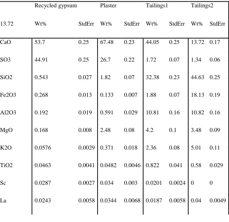
Table 3-1 XRF analysis results ... 52
Table 3-2 General physical properties of the silty tailings. ... 60
Table 3-3 Physical properties of the used acrylic polymer. ... 63
Table 3-4 Physical properties of the resulting final product of emulsified polymer. ... 63
Table 3-5 Combination made for optimization work for traditional admixture. ... 77
Table 3-6 Tailings properties ... 94
Table 4-1 the number of activated rock-filling layers for different cases After Ormann (2013). ... 111
x
List of Figures
Figure 2-1 Typical cross-section of conventional water retention dam (After Priscu, 1999). ... 14
Figure 2-2 Hydraulically& mechanically built upstream tailings dams(After Jeyapalan, 1980). 16 Figure 2-3 Downstream built dam (After Rout et al., 2012) ... 17
Figure 2-4 Centerline method construction sequence (After Priscu, 1999). ... 18
Figure 2-5 Arbitrary slip surface location&the different forms of shearing (After Mesri, 1989) 22 Figure 2-6 Mohr-Coulomb failure envelope for undrained cases. ... 23
Figure 2-7 Su dependency on the shearstrain rate (after Kulhawy and Mayne, 1990). ... 24
Figure 2-8 Large strain consolidation tests by Kabwe et al. (2013) &Gan et al. (2011) ... 28
Figure 2-9 Wide range of tailings gradation. ... 31
Figure 2-10 Decreasing k value with respect to void ratio (After Seneviratne et al., 1996). ... 34
Figure 2-11 Aerial view of the breach at Merriespuirt gold tailings dam (After Fourie et al.) .... 36
Figure 2-12 Piezocone results of Qtip and u2 pore pressure measurements ... 37
Figure 2-13 Aftermath laboratory testing of undisturbed tailings (After Fourie et al., 2001). ... 38
Figure 2-14 CPTu profile of upstream gold tailings dam by Anderson and Eldridge (2001). ... 39
Figure 2-15 Contractive behavior of CU tested tailings (After Anderson and Eldridge 2001). ... 40
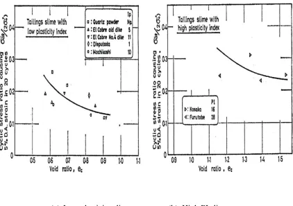
Figure 2-16 Effect of fine content on the CRR value. ... 42
Figure 2-17 Effect of void ratio and PI on the CRR value. ... 42
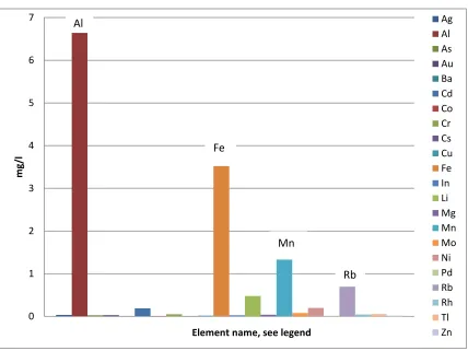
Figure 3-1 ICP test’s results. ... 51
Figure 3-2 Sedimentation or self-consolidation process ... 56
Figure 3-3 Sieve analysis test and hydrometer test’s graph. ... 59
Figure 3-4 a) the tools used for the dewatering setup; b) perforation to allow collecting water .. 65
xi
Figure 3-6 Cv values at different effective stresses of untreated material. ... 68
Figure 3-7 Volumetric strain of untreated tailings versus log σ’. .. Error! Bookmark not defined. Figure 3-8 Void ratio- logarithmic effective stress plot of the different investigated percentages. ... 73
Figure 3-9 Volumetric strain-logarithmic effective stress relationship. ... 74
Figure 3-10 Preparation of B, a) recycled gypsum (B) ready for grinding; b) final product. ... 76
Figure 3-11 Shacking table used to expulse air within. ... 78
Figure 3-12 UCS Sample setup... 79
Figure 3-13 Failure plans for two sheared samples. ... 79
Figure 3-14 UCS of the five combinations for the period of testing. ... 81
Figure 3-15 UCS of tailings treated with 10% admixture CKD: B ... 82
Figure 3-16 Stress-strain relationship of tailings2 treated with (1CKD:2B) ... 83
Figure 3-17 Freshly casted treated tailings1 DS samples. ... 85
Figure 3-18 Untreated tailings Sheared DS sample. ... 86
Figure 3-19 Shear strength envelope of untreated tailings. ... 88
Figure 3-20 Shear strength envelope of 7.5 % (1CKD:1B:1OC) treated tailings. ... 89
Figure 3-21 Shear strength envelope of both treated and untreated tailings. ... 90
Figure 3-22 log σ’ curves of treated and untreated tailings. ... 91
Figure 3-23 Volumetric strain-logσ relationship of all treated and untreated tailings... 92
Figure 3-24 hydraulic conductivity of the untreated tailings versus effective stress. ... 92
Figure 3-25 k- effective stress relationship for (1CKD:1B:1OC) treated tailings. ... 93
Figure 4-1 k-matric suction relationship of fine and coarse soils (Seep/W tutorial, 2012) ... 101
Figure 4-2 Areal view of Aitik tailings impoundment (After Ormann et al., 2013) ... 106
xii
Figure 4-4 Cross section of the dam to be replicated with all the proposed rock-fill banks. ... 110
Figure 4-5 Case I where no rock-fill layer is added except the existing ones ... 110
Figure 4-6 Details of the rock-filling option utilized (light green color). ... 110
Figure 4-7 Safety factors versus number of years (Ormann, 2013). ... 112
Figure 4-8 the simplified version of the published model. ... 113
Figure 4-9 Excess pore pressure after constructing the second layer. ... 114
Figure 4-10 Excess pore pressure after the consolidation time for the second layer. ... 114
Figure 4-11 Figure10: Excess pore pressure after placement of 11th rise. ... 115
Figure 4-12 Excess pore pressure after consolidation of 11th rise (After Ormann et al., 2013). 116 Figure 4-13 EPP after 2nd layer placement of the published model(After Ormann et al., 2013).114 Figure 4-14 EPP after consolidation finished for the 2nd layer (After Ormann et al., 2013). .... 115
Figure 4-15 Excess pore pressure after placing the 11 lift (After Ormann et al., 2013)... 115
Figure 4-16 After the dissipation of the 11th lift’s EPP (After Ormann et al., 2013). ... 116
Figure 4-17 Safety factors computation versus the number of years... 117
Figure 4-18 Variation of computed safety factor versus time. ... 119
Figure 4-19 Slip surface location for first layer. ... 120
Figure 4-20 Slip surface location for 7th layer. ... 120
Figure 4-21 Slip surface location for 11th layer. ... 120
Figure 4-22 Total settlement for case I, untreated, after consolidation of 11th layer took place. 121 Figure 4-23 Total settlement for case I, treated, after time of consolidation of 11th is finished . 122 Figure 4-24 S.F of case IX with treated tailings shear strength and k parameters. ... 123
Figure 4-25 Case I S.F variation versus number of years considering k max and min ... 124
xiii
1
Chapter1
1
1.1
Introduction
1.1.1
Preface
Tailings are byproducts or “wastes” of mining activities. They result from the crushing and
grinding of rocks done in order to extract the “ore”. Typically, the ore percentages within the raw
material are between 30 to 0.4%, which means massive amounts of mined materials are disposed
of daily (Zardari, 2013). A single mine may produce tailings in the order of 1 to 6 million cubic
meters per year. The range of increase in height of tailings deposits depends on the area available
and the amount of yielding. The reported heightening rate is in the order of 2-9 m yearly. This
situation has resulted in the construction of super giant tailings storage facilities, up to 250m high
has been reported (Villavicencio, 2013). As tailings are used in the construction of these
containment facilities, the knowledge of their properties becomes crucial for the safe design of
the impoundments they form.
All tailings containment dam types are built in stages. Therefore, it is necessary to carefully
evaluate the loading/excess pore pressure (EPP) generation, for wet disposal, and the subsequent
consolidation behavior. Because of the problem complexity and the large scale of tailings dams,
numerical modeling is usually pursued to aid in understanding the expected effects of this
loading cycle on the tailings dam stability when staged construction is followed (e.g. Zardari,
2013; Orman et al., 2013).
The upstream construction method is the dominant construction method employed in practice
because it is the most economic and efficient way for disposal of large amounts of tailings
(Priscu, 1999; Ates, 2013; Naeini et al., 2011, Rout et al., 2013). However, this method was
2
take place (Villavicencio, 2013). Thus, some mine companies are forced to adopt other methods
of construction, which makes the construction of containments much more expensive and time
consuming. Nevertheless, mine operators are inclined to adopt the upstream construction
technique due to its cost effectiveness and simplicity. Therefore, several soil improvement
methods are explored to help enhance the safety of tailings dams constructed using the upstream
construction technique.
The effect of soil treatment on the stability of tailings dams is assessed in the current study in
terms of the overall safety factor. The main objective of this thesis is to assist mine operators,
who mostly choose upstream tailings method due to its simplicity and economy, to meet the
safety requirements of the code enforced, and to protect the people and environment surrounding
mine activities.
1.2
Background
1.2.1
Main Tailings Dams
Significant research done on conventional earth dam performance enabled a deep scrutiny of
the adopted practice for their design and construction, consequently, amendments were done
where necessary. Therefore, sound design, management guidelines, and construction practices
were thoroughly revised and have been established. Unlike conventional earth dams, tailings
dams have received little attention by researchers until recently. On the other hand, the literature
contains plenty of reported tailings dams’ failures (Rico et al., 2008; Davis, 2002). Therefore,
thorough analysis and assessment are necessary to find out the prevailing modes of failures and
3
Generally, tailings dams are composed of fine or granular soils usually characterized by low
shear strength and varying particle size distribution. The properties of tailings are highly
dependent on their parent materials, the processes they undergo until the ore is extracted, and the
disposal method (Moghaddam, 2004; James et al., 2002; Priscu, 1999). They are mostly fine
materials with angular texture with particle size range between fine sand to clay. They typically
have low hydraulic conductivity due to their angular particles shape, which affects their drainage
and their response to any hydraulic gradient change. Likewise, their shear strength parameters
are affected by the crushing and grinding and by the properties of the parent rock. Additionally,
the shear strength of the tailings deposit is influenced by how tightly packed the particles, which
will depend on their sedimentation process, particles roundness, velocity of sedimentation and
particles fineness.
The large quantities of tailings make it burdensome task for mine operators to tackle on less
laborious and cost effective way. Therefore, tailings are mostly mixed with water and pumped to
a pond that is contained by artificial or natural impoundments, or a combination of the two.
There are numerous methods for the disposal of tailings; nonetheless, the predominant one is the
formation of tailings dams. Different types of tailings dams are employed depending on the
amount of sand yield. However, following no or little geotechnical guidelines in the initial
practice of their construction made them prone to failure events that endanger the environment
and, if there is any, the downstream inhabitants (Jeyapalan, 1980). The hazard level associated
with tailings dam failure will depend on many factors, including, but not limited to: the volume
released and its travel distance; the level of toxicity of the released volume; the closeness of any
river or stream; and the existence of close human habitats. For instance, the failure events of El
4
Creek dam, West Virginia, USA (1967) are three examples of those calamities which have been
reported to claim more than 550 people’s lives (Jeyapalan, 1980; Yin et al, 2011; Villavicencio,
2013).
Tailings dams operations can be classified into active, inactive, and inactive but monitored.
Many incidents and/or failures of tailings dams reported in the literature resulted mainly from the
following: slope instability, liquefaction, increase in the phreatic level, piping, and overtopping
(Zardari, 2013; Rico, 2008). Therefore, the scope of this thesis is to first gather and analyze
information about tailings and their disposal, review the adopted practice and the associated
problems with it and bring solutions accordingly.
1.2.2
Failure Triggering Mechanisms:
Villavicencio et al. (2013) studied the incidents and failures that took place over a 100 years
period and reported that both active and abandoned tailings dams experienced failures. They
reported that tailings dams can fail due to one of the following causes: the construction method
(upstream method accounts for the majority of sand tailings dams’ failure); poor compaction,
high fine contents in the cyclone sand, and the elevated pore water pressure (Rico et al., 2008;
Davis, 2002). Those causes can initiate the dam instability and consequently lead to incidents
and/or failure. Incidents or failure may happen when excessive deformation occurs at the crest or
toe of the embankment as a result of construction on weak foundation material such as soft clay.
Additionally, failure may happen when the construction sequence does not allow the excess pore
water pressure to dissipate, leading to elevated water table in the dam body, especially if not
considered or predicted in the design stage. Elevated water table can also happen after a rain
storm or high surface run-off. Failure can also happen due to earthquake loading, which causes
5
consequently, reduces the available shear strength. For example, Villavicencio et al. (2013)
reported that most of Chilean sand tailings dams were observed to have clear water pond close to
the crest of the retaining dyke. This is an indication of liquefied material and explicit outcome of
raised water table and poor liquefaction countermeasure (Villavicencio et al., 2013).
Furthermore, slope instability during earthquakes may occur due to seismic inertia forces,
especially when the slope has a low static factor of safety approaching a unity. Also, static
liquefaction can take place when the time laps between two consecutive layer placements is not
adequate to allow for pore water pressure generated to dissipate resulting in full or partial
liquefaction for the dam body and/or the foundation due to the negation of effective stresses. It is
believed that this phenomenon accounts for the majority of reported incidents of failure as those
tailings dams are normally consolidated and their stability depends on the effective shear
strength provided at the slip surface; when the effective strength decreases, the factor of safety
decreases. It is surprising that most of the incidents and/or failures that happened in Chile are for
dams having crest height less than 40 meters. Conversely, the Mauro dam, located in Central part
of the seismic active region in Chile, sustained the earthquake of Feb.2010 having a magnitude
Mw = 8.5 because of its good drainage system along with good design and construction practice,
even though it was 150m high at the earthquake time (Villavicencio et al., 2013). This clearly
indicates the importance of good design and construction practice. Therefore, it is of utmost
importance for the mining industry to design tailings dams to meet safety requirements
implementing construction methodologies that ensure satisfactory performance under different
6
1.2.3
Regulations
Recent incidents and failures have increased public and practitioners awareness of the risks
associated with the mining industry and thus urged the regulatory bodies to enforce sound
regulations and rules for mine tailings disposal. Failures of tailings dams of El Cobre, Chile
(1965), an iron tailings dam in China (2008), and Buffalo Creek, West Virginia, USA (1967) are
three examples of those calamities which have been reported to claim more than 550 people’s
lives (Villavicencio, 2013; Yin et al, 2011; Jeyapalan, 1980). A review of the failure events
spanning throughout the last century gave an insight of the importance of understanding mine
tailings dams’ behavior upon loading, wetting-drying cycles and at the onset of an earthquake
event. Those studies were then used to establish guidelines for the design and maintenance that
mine operators need to comply with. As the construction sequence covers the entire life of the
mine operation, which lasts tens of years, the dam stability is governed by several factors: heavy
rainfall, overtopping, flooding, seismic event and liquefaction. Researchers and mining
companies have consequently been involved in gathering and assessing information about failure
incidents. Throughout the past 3 decades, lessons learnt from previous incidents were the major
driving factors behind reforming mine by-products disposal's regulations. For instance, in Chile,
the regulations of mining byproducts disposal have been modified after an earthquake struck the
west part of the region in 1986 and initiated slope instabilities at some tailings dams. Major
contributions on tailings storage facility guidelines is credited to: Canada, Australia, and South
Africa, as they have more than 1000 tailings dams (Engels, 2012). Worldwide, it is estimated
that tailings dams are in the order of tens of thousands (Zardari, 2011, Yin et al, 2011).
There are two associations that concern tailings dams’ guidelines in Canada, which have
7
Association of Canada (MAC; 1998 and 2003) and Canadian Dam Association (CDA, 1999).
Nonetheless, the tailings dams’ regulation in Canada is controlled by provinces within which
they are located and additional restriction and/or guidelines may apply except for the Uranium
tailings facilities which are controlled by the federal government. Similarly, in Australia, each
state has its own guideline to control tailings disposal. The International Commission on Large
Dams (ICLOD) has established a committee concerning tailings dams and has published eleven
bulletins on their management, operation and closure. All these documents are collaborative
efforts and were established by gathering information from published work and research.
1.3
Objectives and Scope of Research
The main objective of this research is to establish an efficient soil treatment scheme that can
help enhance the stability of tailings dams constructed using the upstream method. In order to
achieve this objective, it is necessary to investigate the beneficial effects of different soil
additives, both non-traditional and traditional, with regard to enhancing the stability of tailings
dams. Therefore, the study has two main components: an experimental component and a
numerical investigation. The experimental component involves the study of employing different
additives to improve the shear strength of tailings material in a laboratory setup. The numerical
investigation is focused on evaluating the stability of tailings dams considering both untreated
tailings and treated tailings. The efficiency of the tailings treatment is then evaluated in terms of
the increase in the factor of safety of the tailings dam. A baseline had to be established in order
to compare the stability of the improved tailings with respect to the stability of untreated tailings.
Typically, tailings dams are constructed to retain the “wet tailings” that resulted from the mining
activities. This kind of facility is conventionally referred to as a tailings storage facility (TSF). A
8
mineral(s) is/are feasible to extract and before the mining activities commence, a starter dike is
usually built from borrowed materials to establish a pond for the first years of mining. As the
pond starts to fill up, the tailings dam has to move upward in one of three directions, which
defines the name of construction method followed. If the tailings dam center is kept and the crest
is raised over the initial dike, then centerline method is adopted. If the center is changed to the
upstream or to the downstream, then upstream or downstream method, respectively, of
construction has been followed. The focus of this thesis is the upstream tailings dams, in which
case the contained tailings are often disposed of in a form of slurry by spigot(s) to ease the
dumping process and to reduce the cost of transportation. Therefore, water contents are usually
very high especially near the surface for newly deposited materials yielding a very weak
material. Over time, some of those contained tailings sediments become part of the tailing dam
(Bjelkevik, 2005). As the mining activities continue, so does the construction of the TSF. The
spigot(s) is progressively moved towards the TSF center and upward with time for upstream
tailings dams; thus, the encapsulated tailings materials within the critical slip surface get larger
and larger. Therefore, the properties of the tailings become critical from a stability point of view.
In the current study, the evaluated tailings properties in addition to the unit weight are: friction
angle, cohesion, Young’s modulus and hydraulic conductivity. In an upstream built dam, the
improvement sought after should manifest itself in the form of increased cohesion of the tailings
matrix, otherwise a non-cohesive material due to the nature of deposition being in a slurry form
that results in a normally consolidated deposit. This concept is commonly referred to as
consolidated tailings or composite tailings, CT (Beier, 2015).
1.4
Research Methodology
9
1- Conduct a comprehensive literature review of tailings dams, their method of construction
and properties.
2- Assess the statistical data published in the literature related to the types of TSF and the
merits and demerits of each type, and define the TSF type that has constructability advantage
while having the potential to significantly benefit from tailings treatment.
3- Upstream tailings dam was selected based on the research efforts stated above.
4- Given that the literature review indicated that excess pore water pressure is the leading
cause of instability incidents, effective stress analysis (ESA) of tailings dams is adopted in the
study.
5- An experimental program involving testing treated and untreated specimens of tailings
material retrieved from mines in Northern Ontario. The tailings treatment investigated included
utilizing both traditional and non-traditional additives.
6- A numerical investigation was conducted considering a configuration of tailings dam that
was constructed using the upstream method (Zardari, 2013) to investigate the effectiveness of the
additives on the chosen tailings dam’s stability.
1.4.1
Lab Testing Programme
To accomplish the aforementioned goal, a set of lab tests had been conducted, including;
1- ICP tests.
2- X-ray Fluorescence tests.
10 4- Hydrometer tests.
5- Specific gravity tests.
6- Unit weight determination.
7- Water content determination.
8- Column sedimentation test.
9- Consolidation tests.
10- Unconfined compressive tests.
11- Direct shear tests.
The tailings tested included two different types. No general information was provided with
them due to confidentiality reasons. Thus, their chemical compositions were evaluated to identify
any source of hazard from them. They were also tested for geotechnical properties inside the
geotechnical engineering laboratory of the University of Western Ontario.
1.5
Thesis organization
This thesis is organized in 5 chapters as follows.
Chapter 1 describes the problem investigated and the organization of the thesis structure and
addresses the objectives and methodology of this research
Chapter 2 literature review of tailings dams is presented. Methods of tailings dam construction
used in practice are also discussed as well as merits and demerits of each type.
Chapter 3 presents the characteristics of the mine tailings investigated. The fundamental
11
untreated mine tailings are addressed and their results are presented and discussed. The samples
used and the preparation methods adopted for each test is described and commented.
Chapter 4 discusses the used approach for slope stability enhancement. After that, the model
used is presented and discussed.
Conclusions of research outcomes and the attained objectives are summarized in chapter 5,
12
2
Chapter2
13
2.1
Definition
Mine tailings are the mine waste or mine by-products, which result from the mining
operations while the ore matter is extracted. Typically, ore concentration in the processed
minerals ranges between 1-30% with the remaining being mine wastes (Villavicencio, 2013;
Bjelkevik, 2005). As a result, tremendous amounts of mining materials become waste with its
subsequent disposal constituting both financial burdens and environmental threats. Annually,
millions of tons of mine tailings are disposed of. To exemplify, in Chile, a million tons of mine
tailings is generated daily. Furthermore, the global mine tailings from the aluminum industry
reached 75 million tons in 2012 (Rout et al, 2012). However, a considerable amount of the
tailings is used in constructing tailings dams, which, in turn, reduces the need for conventional
water retention dams and the associated high cost of borrow materials. A typical water retention
dam is depicted in Figure2-1. Using such a dam can have the following advantages:
A. Dam can be built to its full height prior to mine operation.
B. Surveillance of the dam construction can be carried out easily.
C. Dam faces can be protected against erosion.
However, the drawbacks associated with this type of dam include:
I. Increased initial cost.
II. Requires a source of borrow materials.
In addition, disposal cost, environmental and physical complications of tailings disposal still
14
Figure 2-1 Typical cross-section of conventional water retention dam (After Priscu, 1999).
2.2
Risks
The vast area needed for waste disposal and the associated cost indicate the importance of
sustained research efforts to identify efficient and reliable methods for their disposal. The cost of
disposal will vary from one location to another and will depend mainly on the method of disposal
employed and the distance to the dumping location. Nevertheless, eliminating the need for
borrowed materials for the staged construction of the impoundment can reduce initial cost and
required land (Priscu, 1999). However, because of their massive quantities and their random
composition, mine tailings dams can have tremendous risk for the surrounding areas. This risk
may be magnified due to seismic hazard, the weakness of the impounding materials, the toxicity
of the retained wastes, the frequent occasions of heavy rainfalls, and the high phreatic level.
The main purpose of the enclosed pond method of construction is to retain the wet tailings,
which are pumped into the progressively heightened impoundment(s). Thus, it offers cost
15
increase the risk of slope instability. There are various methods for impoundments construction.
Economically, and to some extent environmentally, the preferred method is to use the mine
wastes themselves in the embankments body in staged construction as the tailings will be
disposed of at the same location, thus eliminating transportation cost. However, the use of
materials that are strong enough to satisfy the stability requirements and meet the environmental
restrictions is essential. As such, separation of tailings into coarse and fine materials is common
to use the coarser stream in the construction of the dam’s outer shell. The separation can be done
by various measures such as spigotting, hydro-cyclones, and centrifuges. Accordingly, whether
or not to exploit the mine tailings in the tailings dam’s construction is dictated by the amount of
sand yield. As far as the sand tailings embankments are concerned, three methods of staged
construction exist: Upstream method, Downstream method and Centerline method. Those
methods are discussed briefly in the following section.
2.3
Methods of Constructions
2.3.1
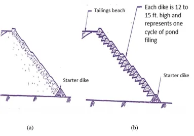
Upstream Method
This method involves raising dikes successively moving from the so called starter dike
towards the center of the bond. It takes advantage of self-consolidating beach where the coarse
particles settle close to the discharge spigot forming a beach while the finer materials flow away
making slimes. In this construction method, two approaches are used, namely; mechanical and
16
(a) (b)
Both methods utilize pipelines for slurry transportation but the mechanically constructed dam
(Figure 2-2b) has some merits over the hydraulically built dam in that the sand beach is
compacted, resulting in a stronger outer shell that will promote dam stability.
2.3.2
Downstream Method
This method is safer than the upstream method though less used in practice, because its use is
subject to the amount of sand yield and, most importantly, the geotechnical construction
regulations (Jeyapalan, 1980; Priscu, 1999). For instance, after the disastrous earthquake event in
1965 that resulted in the liquefaction of El-Cobre mine, re-assessment of adopted construction
practice of mine tailings was necessitated by the government authorities. According to the Figure 2-2 (a) hydraulically and (b) mechanically built upstream tailings dams
17
assessment’s findings, mines authorities abandoned the use of mine tailings in the construction of
tailings impoundment. However, the associated cost with the borrow materials and the
environmental implication of the tailings themselves were still unresolved, which underscored
the need of a more rational assessment that balances safety and economy. Consequently, the
Supreme Decree (1970, Chile) has allowed mine tailings use in tailings dams; however, it
abandoned the use of upstream construction method. Though no sound rules were developed,
some common features of the past failures had made it clear that upstream method of
construction accounts for most of the failure and incidents (Villavicencio, 2014). Therefore,
mine operators were left with choosing either the downstream or centerline method. Figure2-3
shows typical sequence of downstream sequentially raised embankment.
The trapezoidal shapes represent the dikes built to retain the pond to their left. The main
18
Figure 2-4 Centerline method construction sequence (After Priscu, 1999).
2.3.3
Centerline Method
Similar to the downstream method, the centerline method requires high sand yield. However,
dikes are raised from both upstream and downstream sides of the starter dike, unlike the
downstream method whose crest in shifted progressively towards the downstream side of the
started dike. However, in the centerline method, both the fine and coarse materials are used in
the construction of the upstream and downstream rises, respectively.
2.4
Pre-Dewatering
2.4.1
Thickeners
One way to produce an easy to reclaim soil layer is by utilizing thickeners. Thickeners
operate as a vesssel which employs a gravimetric sedimentation procedure where the slurry is
poured into them and allowed to settle. Once settled, the thickened soil layer is removed as
19
stronger, thereby easier to reclaim soil. It utilizes less water than natural dewatering method due
to seepage and associated consolidation since the collected water can be further circulated to the
mill and back to the sedimentation tank. Besides, coagulant can be used to expedite the rate at
which particles settle.
2.4.2
Hydro-Cyclones
Hydro-cyclones are used to separate the coarse tailings, more than 0.075mm, and the fine
tailings, less than 0.075mm. They operate by utilizing the centrifugal forces that act on the heavy
soil particles when they enter from the top in a trajectory motion as a slurry to separate them
from the fine particles. This happens as the slurry enters the hydro-cyclone in high speeds and
spins around the inverted cone where the coarser particles are attracted to the cone-wall and the
fine particles remain suspended in the water. The coarse particles make their way to the bottom
where they are collected as underflow and the fine particles that remain in suspension exit from
the top as overflow. The underflow is, however, not completely separated from fines. Once
separated, the fine particles are either further processed for dewatering or pipeline transported to
containment(s). The underflow is typically used for the outer shell of the impoundment which
results in much stronger containment and a low hydraulic gradient; otherwise, they are
stock-piled as a single or groups of piles which results in a robust embankment that requires less
footprint.
2.4.3
Centrifuges
Centrifuges can be used to produce a “cake” of soil that is best suited for reclamation
purposes. The centrifuge in this case is a rotating drum, which has two ends; one for inlet and the
20
covered with a filter for decanting purposes. When the slurry enters the centrifuge, the rotational
motion drags the slurry to the wall whereby the centrifugal forces attracts the heavier soil
particles and two distinct regions form, one is a “cake” of compressible soil where particles are
almost fully in contact with each other and the other is free water zone. This will allow an
efficient water circulation mechanism and drier materials. This material is then collected and can
be transported by conveyors or trucks for stacking. This method is also suitable should usage of
tailings outside the mine location be required (Beier, 2015).
2.5
Post Dewatering
Post dewatering happens after the tailings are dumped into their permanent location. The
tailings start draining their water instantly after they arrive to the final destination where they
start transitioning from a viscous liquid into a soil medium. During this process, deposited
tailings experience large strains. Typically, the coarser particles will settle close to the discharge
point creating a beach while the finer particles travel a distance with the slurry into the pond
where they settle making slimes. Once dumped, the soil particles begin settling and the
soil-water interface lowers whereby two distinctive regions form; a settling zone and free soil-water. With
time, a cake is formed in which the lower part is of lower water content than the top (Kabwe et
al., 2013). This cake transforms to become a layer with time, where its weight affects the
consolidation process. As the deposition continues, this layer becomes several layers that are
self-consolidating due to the successive loading, generation and dissipation of excess pore water
21
2.6
Shear Strength Parameters
2.6.1
Anisotropy
Laboratory testing should be properly interpreted and must take into account the differences
between field and lab conditions. The disturbance, moisture migration and stress relief should
also be considered for samples retrieved from the field. Furthermore, the sampling and
preparation methods should be appropriate for the analysis aimed. This truly holds when the
analysis concerns facilities or structures built on top of layered strata, like varved clay, where
deposition process has resulted in either stress or structural anisotropy (Chen et al., 2014). In
mine tailings dams, this situation will inevitably exist as the mining deposits are being built
successively. For slope stability problems, when the soil is tested for the shear strength
parameters, caution should be exercised as the direction of shearing is neither horizontal nor
vertical but rather curved. In this case, soil anisotropy should be considered in terms of which
direction the samples should be sheared, horizontal (Direct Shear) or inclined (Triaxial
Compression). For cases when testing an already deposited material for slope stability, the shape
of the expected slip surface should be constructed utilizing the Finite Element method and this
information employed to decide on which plane the field sample should be sheared. It is believed
that triaxial compression will mostly provide the best results, and more conservative answers,
about the shear strength parameters of most soils (Vick, 1990; Das, 2006). Chen et al. (2014)
presented a series of lab testing conducted on direct shear box. They noticed that the shear
strength parameters vary according to the inclination of bedding angle with a difference in the
22
Figure 2-5 Arbitrary slip surface location and the different forms of
shearing along it (After Mesri, 1989).
Figure 2-5 clearly shows the variation in shearing direction and the incompatibility of lab
apparatus to replicate all of these forms at once.
2.6.2
Shear Strain Rate
The strain rate used in testing the specimen should correspond to the expected loading
conditions. For example, if high shearing strain rate, such as 0.5mm/min, is used in DST with
saturated clay, excess pore pressure will not have enough time to dissipate resulting in a reduced
confinement on the sample. This, in turn, will violate the use of the effective strength envelope to
get the cohesion and the internal friction angle since the second component of equation 2-1 is no
longer fixed, unless excess pore pressure measurements are available. The following are the used
23
Figure 2-6 Mohr-Coulomb failure envelope for undrained
cases.
τ = c’ + [σ’ tan (Φ’)]……… (2-1)
τ = c + σ tan (Φ) ……….. (2-2)
Equation (2-1) represents the shear strength envelope for drained analysis where the effective
stress stays assumingly unchanged for the case of finite shear strain devices, for the entire time
of one test. For normally consolidated clays and sand, the equation reduces to τ = σ’ tan (Φ’).
Equation (2-2) is the shear strength envelope of undrained analysis and is when excess pore
pressure develops resulting in a reduction to the effective stress applied. C and Φ in this case are
the total strength parameters. In many cases, the right hand side of this equation is ignored and τ
becomes independent of the effective stress amounting to a single value represented by Su, or undrained strength of the soil. This is depicted using Mohr-Coulomb criterion by the figure
follows.
24
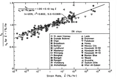
Figure 2-7 Su dependency on the shearstrain rate (after Kulhawy and Mayne, 1990).
Su= 0.22 𝜎𝑝′ ……… (2-3)
However, Mesri indicated that form of shearing, plasticity index, rate of shearing and the
apparatus used can have significant impact on the results. This is consistent with the findings of
Kulhawy and Mayne (1990) who showed that the rate of strain affects whether drained or
undrained conditions exist and the shear strength of the material. Kulhawy and Mayne (1990)
correlated Su values and the strain rate. The correlation is depicted in Figure 2-7, which clearly shows how the undrained shear strength can be 30%−+ its value at 1% strain rate/hour.
The relevance of this to the current study is that the shear strength parameters of the material
25
rates may show higher strength parametes whereby overestimating the stability of the assessed
slope.
2.7
Consolidation
Soil consolidation is a time dependent process resulting from the expulsion of water from the
soil pores. The consolidation settlement consists of primary consolidation and secondary
compression or creep. Primary consolidation is the change in volume of a saturated fine-grained
soil caused by the expulsion of water from the voids and the transfer of load from the excess pore
water pressure to the soil particles. Secondary compression is the change in volume of a
fine-grained soil caused by the adjustment of the soil fabric (internal structure) after primary
consolidation has been completed. The primary consolidation time will therefore be dependent
on the drainage properties; namely, the hydraulic conductivity and the boundary condition. The
Oedometer test results are typically used to establish the coefficient of consolidation, which can
be used to forecast the time necessary for a certain consolidation percentage to take place. The
Cv can be estimated as follows;
Cv=
K
𝑚𝑣ɣ𝑤 ……… (2-4)
where;
K: Hydraulic conductivity
mv: Coefficient of volume change
26
The primary consolidation can be estimated as follows (Das, 2006);
- Sc=
𝑐𝑐∗𝐻
1+𝑒𝑜 log (
𝜎′0+𝜎′
𝜎′0 ) (Normally consolidated deposits)………..(2-5)
- Sc=
𝑐𝑠∗𝐻
1+𝑒𝑜 log (
𝜎′0+𝜎
𝜎′0 ) (Over-consolidated soil with stress increase plus existing
overburden less than the pre-consolidation pressure)………(2-6)
- Sc=
𝑐𝑠∗𝐻
1+𝑒𝑜 log (
𝜎′𝑐
𝜎′0)+ Sc=
𝑐𝑐∗𝐻
1+𝑒𝑜 log (
𝜎′𝑐+𝜎
𝜎′𝑐 ) (Over-consolidated soil with stress increase plus
existing overburden more than the pre-consolidation pressure)…………... (2-7)
Cc and Cs are slopes of virgin consolidation line and rebound swelling (unloading line), respectively. They are estimated from the e-log σ’ curve as follows;
- Cc=
𝑒1−𝑒2
log (𝜎2
𝜎1)
………. (2-8)
- Cs=
𝑒1−𝑒2
log(𝜎2
𝜎1)
………... (2-9)
The previous symbols used are defined as;
Sc: Primary consolidation settlement 𝜎′0: Existing overburden
𝜎′: Effective stress increase
𝜎′𝑐: Pre-consolidation stress
𝑒𝑜: Initial void ratio
H: Thickness of soil layer
Due to complex loading/pore pressure generation and the subsequent consolidation cycle
27
to assist engineers to predict settlement and excess pore water pressure. These sophisticated
numerical tools allow considering staged construction where time and boundary conditions
present a major challenge. The two main constitutive models employed in analysis are
Mohr-Coulomb and Modified Cam-Clay model. In Mohr Mohr-Coulomb model, the Oedometric results are
less valuable compared to the Modified Cam-Clay in the sense that it does not consider the e-log
σ’ curve (soil non-linearity) but rather use the typical stress-strain (simple elastic-plastic)
relationship to account for settlement. However, it is seen to be of acceptable accuracy in
calculating the settlement of such complex load/EPP generation/consolidation behaviour for a
slope stability problem. In addition to its acceptable accuracy, it is simple and requires only five
parameters, in addition to the unit weight, that are easy to estimate. Conventional Oedometer
testing is not suited for slurried mine tailings where the strain level expected is large. What is
also lacking in these conventional consolidometers are the ability to exert very low effective
stresses, between 0.1- 1 kPa, on the slurry. Therefore, Gibson (1967) proposed the following
equation to estimate self-weight settlement.
……..……… (2-10)
Large strain Oedometers have been fabricated and used since then. Nonetheless, the e-log σ’
obtained from these large strain consolidometers defines an effective stress and void ratio
beyond which the slope of virgin consolidation curve stabilizes. This is shown Figure 2-8. What
is of importance to highlight is that this point on the e-log σ’ curve from large consolidometer
testing happens to lie within the small range of effective stresses, between 0.5-1.5 kPa.
Additionally, the slope of the e-log σ’ before the stabilizing point is dependent on the material
28
Figure 2-8 Large strain consolidation tests done on large strain
consolidometers by Kabwe et al. (2013), left, and Gan et al. (2011), right.
can take weeks to finish (Gan et al., 2011). This method can be fitted to the soil of interest and
thus can produce results of acceptable accuracy (Barnekow et al., 1999).
The difference between the initial slopes can be attributed to water content and thixotropy.
Thixotropy is reported to add quasi over-consolidation pressure on the tailings. No settlement
will take place until this pre-consolidation pressure is exceeded (Wilson et al., 2013).
2.7.1
Creep Settlement
Creep is the volumetric reduction of the soil volume at constant stress due to static pressures
at the particle to particle contact that are in excess of what the soil particles can withstand. This
29
consider this soil time-dependent behaviour if suspected, especially when planning mine tailings
dam closure. This problem can lead to very problematic situation if the land is set to be used for
future land development. Secondary consolidation index and Creep settlement can be estimated
according to Das (2006) as follows:
Cα= 𝑒
log (𝑡2
𝑡1)
……….. (2-11)
Where;
Cα: Secondary consolidation index
e: Change in void ratio after primary consolidation phase ends
t1, 2: Two arbitrary times after the end of primary consolidation
𝐶𝛼′= 𝐶𝛼
1+𝑒𝑝………. (2-12)
Ss= 𝐶𝛼′𝐻log( 𝑡2
𝑡1) ……… (2-13)
Where;
Ss: Secondary settlement
H: Thickness of soil stratum
30
2.7.2
Particle Crushing
Particles crushing and grinding cause tailings to become angular and sub angular in shape,
which results in high contact pressures between particles that could lead to particle crushing and
weakening. Therefore, it is important to study the effects of high stresses on tailings where soil
time dependent behaviour is not well understood. In this thesis, however, this issue was not
directly addressed as no long term results were studied to observe the effects of sustained load on
creep and shear strength values. However, the effect of high stresses on the shear strength
parameters was investigated.
2.8
Geotechnical Parameters of Tailings
The typical compression index, Cc, for mine tailings ranges from 0.05 to 0.87 (Qiu and Sego,
2001; Barnekow et al., 1999), and their specific gravity, Gs, varies from 2.65 to 3.97. Water content varies substantially from tailings to tailings with a range of 20-160% and depending on
deposition method, liquid limit of the tailings material and if dewatering is used (Shuttle and
Cunning, 2007; Mahmood and Mulligan, 2010; Qiu and Sego, 2001; Barnekow et al., 1999). The
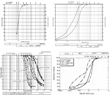
gradation of tailings depends on the parent rock and the degree of crushing and grinding to which
tailings are exposed. A broad range of grain size can happen in one particular tailings, ranging
31
2.8.1
Relative Density
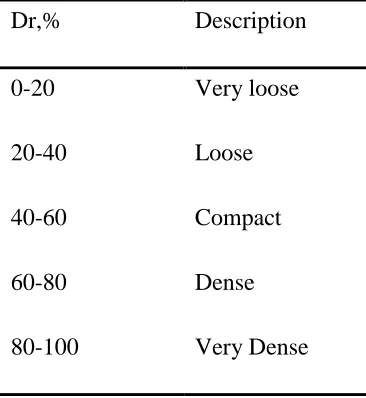
Coarse tailings are found to have relative densities between 40-60% and can be classified
accordingly as loose to compact materials (Kabwe et al., 2013; Anderson and Eldridge, 2011;
Das, 2006; James et al., 2002). Table 2-1 shows soil classification according to their relative
densities.
Figure 2-9 Wide range of tailings gradation (After James et al, 2002; Ozcan,
32
Table 2-2 Typical friction angle range with relative density. Table 2-1 Soil classification according to relative densities.
From this previous information, one can conclude that the angle of internal friction of such
tailings would be between 33-35o (Bery and Saad, 2012). This conclusion agrees well with the range of internal friction angles reported in literature (Ozcan et al., 2012, Zardari, 2013).
Dr,% Description
0-20 Very loose
20-40 Loose
40-60 Compact
60-80 Dense
33
2.8.2
Hydraulic Conductivity
The tailings gradation occupies the region between coarse sand and clay. Most of the tailings
will have a combination of coarse and fine particles. Therefore, it is difficult to characterize the
tailings hydraulic conductivity, k, due to several reasons such as the disposition method and
history, gradation, stress history and so on. Thus, using a single correlation, such as Hazen
equation, to get a single value for hydraulic conductivity is erroneous. For instance, Bjelkevik
(2005) compiled data to compare the lab measured hydraulic conductivities of 7 Swedish tailings
dams and those calculated using two equations, i.e. Hazen (Das, 2006) and Chapius (Bjelkevik,
2005). Bjelkevik found that the ratio of calculated to estimated hydraulic conductivity varied
between the two equations and noted that Chapius equation overly overestimated the hydraulic
conductivity. Though same overestimation was noticed in the case of Hazen’s equation, a lesser
ratio, calculated/measured ratios of k between 2-3, was observed. Nevertheless, it is observed
that using this equation for a certain dam, and for all the sampling locations, had consistently
either over or underestimate the hydraulic conductivity. Furthermore, the ratio between the
calculated and estimated were consistent for the three sampling locations. However, the effects
of sampling, stress relief and stress history were not addressed (Bjelkevik, 2005).
In sub-aerial deposition, the tailings transforms from slurry to suspension to a cake layer, and
finally to a soil deposit under water. They then undergo consolidation due to the staged
construction process, which results in changes in void ratio, porosity, and therefore hydraulic
conductivity. These parameters will affect the hydraulic conductivity and the dam stability.
Therefore, it is important to account for these effects on the hydraulic conductivity value used in
the numerical model, which will dictate how much time is needed to reach a certain excess pore
34
Figure 2-10 Decreasing k value with respect to void ratio (After Seneviratne et al.,
1996).
of k will therefore be dependent on the soil type and stress history. Typical range of k found in
literature is between 1*10-3-1*10-8 cm/sec. (Qiu and Sego, 2011; James et al., 2002).
2.8.3
Rate of Deposition and Dam Slope
There is no rule as to how the tailings dam should be heightened or what slope to use. It is
always dependent on the operator choice which is affected by the available land, volume of
tailings, method of deposition used, amount of sand yield and topography. It is reported that lifts
of thicknesses in the range of 0.15-3m have been used to construct tailings dams (Fourie et al.,
2011; Zardari, 2013). Slope inclination varies from 1:1.5 to 1:5, which also differs for upstream
and downstream slopes. The upstream face of the tailings dam is usually built to a steeper angle
35
2.9
Liquefaction Studies
Fourie et al. (2001) have reviewed the testing campaigns that were launched after the failure
of the Merriespruit gold tailings dam in 1994. They pointed to static liquefaction as a possible
explanation for the failure, which resulted in 17 causalities and 3km of mud and debris. The
incident happened after a rainstorm of 50mm intensity, which caused overtopping and a breach
in the northern wall of the upstream tailings dam. What is of interest is that the tailings disposal
at that pond was halted a year before the incident took place due to high pond level and previous
incidents of sloughing on the downstream face of the portion that later failed. It was mentioned
that while South African tailings dams are allowed to maintain low freeboard, that tailings dam’s
freeboard had happened to be 200mm lesser than the minimum required freeboard of 500mm
established by mining authorities in the county, the 1 in 100 years recurrence of a 24hours
duration storm interval (Fourie et al.,2011). Fourie et al. (2011), have conducted a site
investigation program supplemented by lab testing to test the hypothesis that static liquefaction
was the reason of such catastrophe. Steady state line (SSL) was defined for materials with 60%
fines and field void ratios were established from undisturbed samples and were plotted against
the SSL where it was shown that 61% laid above the SSL which is an indicative of contractive
behavior, or positive state parameter ψ. This review clearly demonstrated the importance of
studying the nature of the tailings and their susceptibility to flow, complete loss of strength, or
36
Figure 2-11 Aerial view of the breach that happened at Merriespuirt gold
tailings dam (After Fourie et al.)
Sasitharan et al. (1994) conducted a consolidated drained triaxial test in which they have kept the
devatoric stress constant and decreased the mean effective stress in order to simulate a raised
water table. They found that the sample failed very quickly for them to record data to the extent
that the loading head had stuck the nuts causing excessive vibration and noise. This is consistent
with the reported noise associated with the failure of Merriespuirt gold tailings dam, which is
indicative of the tailings material having liquefied.
Similarly, Anderson and Eldridge (2011) reviewed the state of a 70 m thick slime deposit at an
upstream tailings dam to assess the potential of slimes’ susceptibility to liquefaction. The
Chinese criteria for liquefaction assessment states that a soil deposit that contains more than 35%
37
Figure 2-12 Piezocone results of Qtip and u2 pore pressure measurements (After Fourie et al. 2001).
observations. This finding was attributed to the fact that the plastic fines hold the soil particles
together. However, recent studies show that soil with fines up to 50% (silts), had liquefied
(El-Takch, 2013; Boulanger and Idriss, 2006). Anderson and Eldrige (2011) conducted triaxial tests
and considered the concept of critical-state soil mechanics to compare the in-situ void ratio with
the critical state line (CSL). They found that, though the tailings were plastic, they have shown
EPP built up and strain softening occurred, which indicate liquefaction can initiate. Fourie et al.
(2001) reported a case study for liquefaction of a tailings dam. Figure 2-12 shows the CPTu
38
Figure 2-13 Aftermath laboratory testing of undisturbed tailings
samples from the failure’s vicinity (After Fourie et al., 2001).
It is clear from Figures 2-12 and 2-13 that the tailings were very soft material, where the cone tip
resistance profile (Qtip) was almost constant throughout the top10 m, within depth where liquefaction has been observed, with a value of approximately 500kPa which is very low. Also,
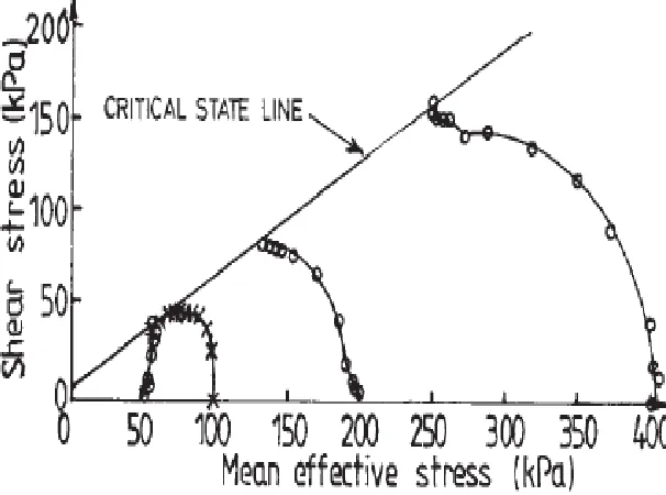
the dynamic pore water measurements, u2 indicate positive sign (contractive behaviour), with values of up to 300kPa being recorded. The consolidated undrained (CU) tests results presented
in Figure 2-13 demonstrate that the tailings displayed a contractive behavior, reduction in
effective stresses and increase in positive pore pressure as shearing continues until CSL is
reached.
Similarly, the CPTu and CU tests of the gold tailings dam (Anderson and Eldridge, 2001)
demonstrated liquefaction behavior. As Figure 2-14 shows, the profile shows 5 m of sandy soil
39
Figure 2-14 CPTu profile of upstream gold tailings dam assessed for liquefaction
by Anderson and Eldridge (2001).
40
Figure 2-15 Contractive behavior for some of the CU tested tailings (After
Anderson and Eldridge 2001).
James et al. (2003) have considered the drawbacks of small conventional testing such as small
sample size and vertical applied stresses. They built a one cubic meter box that goes on a shaking
table to test the effects of overburden, drainage path(s) and heterogeneity on the soil response.
The oscillation produced by the shacking table they used can go up to 3g with the ability to
reproduce any earthquake time history. They have not yet, up to the author knowledge, published
all cases but a preliminary case. The preliminary case they published contains evidence of a
bearing capacity failure at the ground surface which is something James et al. (2003) attributed
to liquefaction, even though the EPP was not measured at the zone of collapse and the other pore
pressure cells did not show EPP high enough to produce zero effective stress. The authors’
conclusion about that is that the small effective stresses, mean of 2.5kPa, helped the soil mass
not to soften and generate liquefaction except at the ground surface where there was a surcharge
of 2.5kPa.
It may be concluded from these cases that mine tailings are susceptible to strain softening and
contractive behaviours, where positive EPP can generate to the extent of soil structure collapse
as the effective stress approaches zero. They help to apprehend the undrained tailings behavior,
which can put the tailings dams’ safety at risk. This has to be addressed in advance of
construction because EPP can develop in any tailings dam due to the staged construction practice
associated with the wet deposition method, which could lead to static liquefaction and/or reduced
effective stresses thereby reduced safety factor of the tailings dam whereby putting the stability