A NOVEL DOMAIN DECOMPOSITION FINITE
DIFFERENCE TIME DOMAIN SCHEME INCLUDING MULTIPLE REFLECTIONS
H. E. Abd-El-Raouf
Department of Electrical and Computer Engineering Kulliyah of Engineering
International Islamic University 53100 Kuala Lumpur,Malaysia
R. Mittra
Electromagnetic Communication Laboratory The Pennsylvania State University
University Park,PA 16802,USA
Abstract—In this paper,we present a new domain decomposition technique which considers the effect of multiple reflections between the subdomains. This method has the ability to simulate accurately large electromagnetic problems that are difficult to handle using the direct application of the FDTD method. The results for the test examples considered in this paper compare well with the direct FDTD solution, and serve to validate the proposed scheme.
1. INTRODUCTION
Despite the continuous increase in the computer resources that enhance our abilities to handle many large electromagnetic problems using parallel processing,simulation of structures that involve inhomogeneous media,complex geometries and multiscale features continue to remain challenging,even when using parallel FDTD
codes. In earlier works,the authors have introduced the domain
decomposition FDTD and the serial parallel FDTD techniques,in [1] and [2],to solve problems of this type by dividing the computational
domain into moderate-sized subdomains. However,only a single
pass through the structure was considered in those works,without
the above approach has been successful for a number of applications considered previously in [1] and [2],in which the multiple reflection effects are relatively weak,it has been found that for some other problems it is necessary to consider the interactions that arise from coupling effects between objects belonging to different subdomains, which cannot be captured in a single pass. In this paper we present an improved version of the Domain Decomposition FDTD (DDFDTD) algorithm that includes the multiple reflection effects alluded to above. Recently,a number of frequency domain methods have been used to solve large electromagnetic problems using the domain decomposition methods [3,4], and some of the other techniques for solving large electromagnetic problems are presented in [5–14].
We begin by investigating the mutual interaction effects for problems that are not electrically large in size; hence the import of these effects is relatively more severe than it is for large problems. We will follow this up later with an example that involves a large electromagnetic problem,the type for which the present method has been designed to handle.
2. METHOD OF SOLUTION
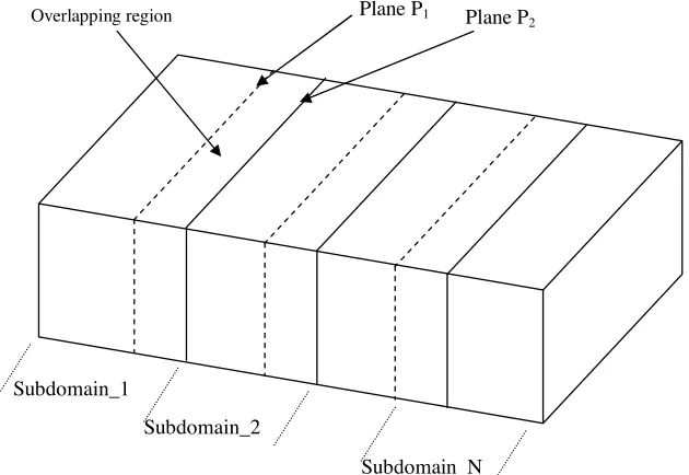
The strategy for Domain Decomposition approach in the time domain is quite different from that followed in the frequency domain,as will be evident shortly. The first step in this method is to divide the computational domain into moderate-sized subdomains such that each subdomain utilizes the computational resources to its utmost,and to employ as many processors as are available when analyzing these subdomains. The FDTD is still applied in a serial manner as explained in [1] and [2],but with a slight difference,in that we now consider the interactions between the different subdomains,as explained in the following. The serial FDTD scheme begins with the subdomain which is excited first (for convenience assume the first domain is on the extremely left). The FDTD is subsequently applied to each subdomain from the left to the right. Each subdomain is terminated by PML to absorb the outgoing waves. The tangential electric fields at the interface,in the plane P1 (Fig. 1),are stored for all the time steps. The region between the two planesP1 andP2 is an overlapping region
which is simulated twice,in subdomain 1 and subdomain 2. This
to obtain convergent results that may require contributions up to
n-reflections,i.e.,“DDFDTD[n]”. It is worthwhile to point out the number of passes n would typically decreases as the object size is increased in a manner such that the spacing between the scatterers residing in the various domains also increase.
Overlapping region Plane P1 Plane P 2
Subdomain_1
Subdomain_2
Subdomain_N
Figure 1. Domain decomposition of the computational domain into N subdomains.
3. RESULTS AND DISCUSSIONS
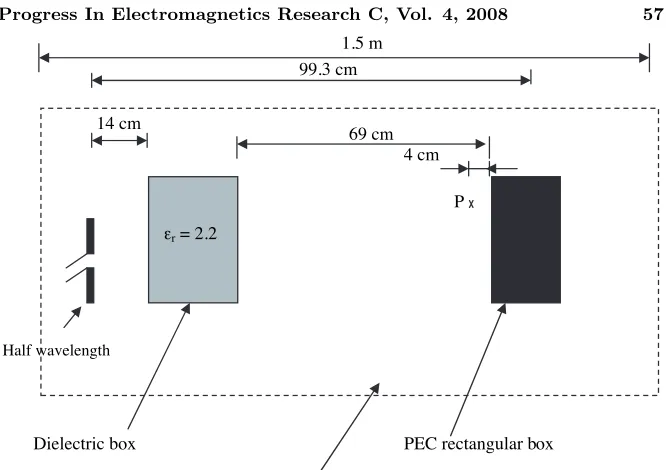
It should be intuitively evident that the coupling effects are stronger in small or intermediate size problems as compared to those for larger problems,thus we begin by testing this technique for structures that are not electrically large. Fig. 2 shows the side view of the first problem which involves a half wavelength dipole placed in front of two rectangular boxes. The resonant frequency of the dipole is 1 GHz,
and the separation between the two boxes is 69 cm. To simulate
the total structure we need to use a computational domain with the dimensions 45 cm×150 cm×48 cm,which is 1.5λ×5λ×1.6λ at
0.5 GHz of the modulated signal. We employ the DDFDTD technique to simulate this problem using two subdomains,with an overlapping region of 15 cm (λ/2 at 1 GHz). In Fig. 3(a),we compare the direct result of the FDTD simulation for the Ez(t) field at point P of
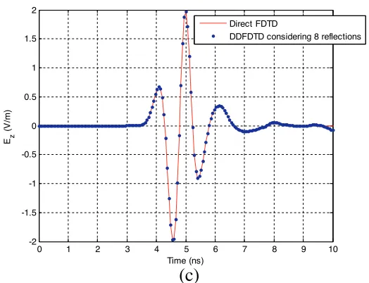
the entire geometry to that derived by using the DDFDTD for two cases: DDFDTD without considering any reflections between the two subdomains (DDFDTD[0]) [1],and the DDFDTD with including up to four reflections (i.e.,two roundtrips) (DDFDTD[4]). It is evident from the figure that the DDFDTD[0]is not accurate for this problem because of strong interactions present between the subdomains. We also note that the DDFDTD[4] yields accurate results for t <7.5 ns,while they deviate from these obtained via the direct FDTD,which of course includes all the interactions. In particular,truncation errors become strong for the time t > 8 ns. Therefore,it is evident that a sufficient number of interactions between the subdomains should be included in the simulation to avoid these errors. Fig. 3(b) shows that FDTD[6] gives good improvement and Fig. 3(c) shows very good agreement between the direct application of the FDTD and those obtained via the DDFDTD[8],where we go up to eight reflections (four round trips of the reflections).
Since one of the key sources of error in the DDFDTD is attributable to the truncation of the subdomains,we attempt to reduce this error by using larger overlapping regions so that the field is stored sufficiently far from the truncation plane. We simulated the previous example of Fig. 2 by using two subdomains with an overlapping region of 1.5λ (λ is the wavelength at f = 1 GHz). The results are shown in Fig. 4 for the two cases DDFDTD[0] and DDFDTD[2]. The figure shows that using a wider overlapping region improves the accuracy of the DDFDTD,and only two reflections (one round trip) are adequate for this problem.
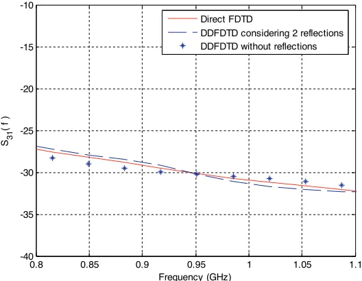
Next we apply the DDFDTD to the problem of four half wavelength dipoles,the first of which is excited while the others are terminated by 50 Ω loads. Fig. 5 shows the geometry of the problem and Fig. 6 compares the result of direct application of the FDTD to those obtained via the DDFDTD[0] and the DDFDTD[2]. The above figure shows that the accuracies of the results of both the DDFDTD[0] and DDFDTD[2] are reasonable near the resonant frequency.
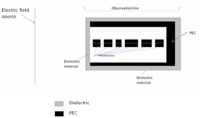
Our next step is to consider the problem of electromagnetic wave scattering from a dielectric-coated conducting rectangular PEC box of Fig. 7. The rectangular PEC box is open in the front and it is coated by a dielectric material with εr = 2.2 and thickness
1.5 m
Half wavelength
PEC rectangular box
εr = 2.2
Dielectric box
99.3 cm
14 cm
69 cm
P 4 cm
The computational domain (1.5λ0 x 5λ0 x 1.6λ0), f0=1GHz
Figure 2. Problem of a dipole located in front of two rectangular boxes.
5.5 cm. The source is an electric field with Ez polarization,which is located in a plane at 7 cm from the front face of the structure. The field source is a modulated Gaussian pulse with a modulation frequency of 1.5 GHz and a 3 dB bandwidth of 1.5 GHz. The inner
dimensions of the PEC rectangular box are 9 cm×93 cm×13 cm.
The thickness of the metal walls is 3 cm. Inside the rectangular
box,there are six small metallic boxes. The dimensions of these
boxes are 5 cm×5 cm×5 cm,5 cm×7 cm×5 cm,5 cm×5 cm×5 cm, 5 cm×10 cm×5 cm,5 cm×10 cm×5 cm,and 5 cm×7 cm×5 cm. The computational domain for this problem has the dimensions of 45 cm×150 cm×55 cm,i.e.,it is 4.5λ×15λ×5.5λin terms of the free
space wavelength atf = 3 GHz. We apply the DDFDTD to simulate
this problem using two subdomains with an overlapping region of 20 cm. The direct FDTD and the DDFDTD[2] solutions for theHx(y) field distribution along the central lineY Y are compared in Figs. 8(a) and (b) for the frequency f = 1.5 GHz. We note that there is good agreement between the results obtained by the two methods.
0 1 2 3 4 5 6 7 8 9 10 -2
-1.5 -1 -0.5 0 0.5 1 1.5 2
Time (ns)
Ez
(
V/m)
Direct FDTD
DDFDTD without reflections DDFDTD considering 4 reflections
(a)
(b)
0 1 2 3 4 5 6 7 8 9 10
-2 -1.5 -1 -0.5 0 0.5 1 1.5 2
Time (ns)
Ez
(
V/
m
)
Direct FDTD
(c)
0 1 2 3 4 5 6 7 8 9 10
-2 -1.5 -1 -0.5 0 0.5 1 1.5 2
Time (ns)
Ez
(
V/m
)
Direct FDTD
DDFDTD considering 8 reflections
Figure 3. Comparison of Ez(t) at pointP for the direct application of the FDTD for the entire geometry of Fig. 2 with the DDFDTD using two subdomains: (a) DDFDTD[0] and DDFDTD[4]; (b) DDFDTD[6]; and (c) DDFDTD[8].
0 1 2 3 4 5 6 7 8 9 10
-2 -1.5 -1 -0.5 0 0.5 1 1.5 2
Time (ns)
Ez
(
V/m
)
Direct FDTD
DDFDTD without reflections DDFDTD considering 2 reflections
Figure 4. Comparison ofEz(t) at pointP for the direct application of the FDTD for the entire geometry of Fig. 2 with the DDFDTD[0] and
DDFDTD[2] using two subdomains when we used longer overlapping
50 50 50
The computational domain (1.5 x 6 x 1.6 )
1.63 1.5λ 0.63λ
Transmitting dipole
Dipole _1 Dipole _2 Dipole _3 Dipole _4
Terminated dipoles
50
50Ω 5050Ω 5050Ω
The computational domain (1.5λx 6λx 1.6λ)
3λ
Transmitting dipole
Dipole _1 Dipole _2 Dipole _3 Dipole _4
Terminated dipoles
Figure 5. Side view of the problem of calculating the S-parameters of four half wavelength dipoles.
0.8 0.85 0.9 0.95 1 1.05 1.1
-40 -35 -30 -25 -20 -15 -10
Frequency (GHz)
S31
( f )
Direct FDTD
DDFDTD considering 2 reflections DDFDTD without reflections
Figure 7. Problem of scattering from a dielectric-coated conducting rectangular PEC box.
30 40 50 60 70 80 90 100 110 120 130 0
0.5 1 1.5 2 2.5
M
ag(
Hx
(y
))
(A
/m
)
DDFDTD considering 2 reflections Direct FDTD
y (cm)
(a)
30 40 50 60 70 80 90 100 110 120 130
-200 -150 -100 -50 0 50 100 150 200
y(cm)
Pha
s
e
(H
x
(y
))
d
e
g
DDFDTD considering 2 reflections Direct FDTD
(b)
Figure 8. Comparison of the results of the DDFDTD and the direct application of FDTD for the Hx(y) at f = 1.5 GHz along the observation line Y Y,shown in Fig. 7.
1000 1500 2000 2500 3000 3500 4000 -3
-2 -1 0 1 2 3 4 5
Time steps
Ez
(
V/m)
Direct FDTD
DDFDTD considering 2 reflections
respectively (the structure is similar to Fig. 2,but the materials and the dimensions are different). The dimensions of the computational domain in terms of the minimum wavelength in the dielectric material of the second parallelepiped (εr = 4) are 9λ×60λ×9.6λ.
The first parallelepiped has dimensions of 4.2λ×12.2λ×3.6λ while the corresponding volume for the second is 3λ×14λ×3.6λ. The separation distance between the two parallelepipeds is 21λ. The dipole antenna is located at a distance 1.7λfrom the first parallelepiped. A comparison of the results for Ez(t),computed at a point between the two objects and located at a distance of 1.5λ away from the second parallelepiped (εr = 4),is shown in Fig. 9. Good agreement is seen
between the results of the direct application of the FDTD and those obtained via the DDFDTD[2].
4. CONCLUSION
A new domain decomposition FDTD,which includes the multiple interaction effects between the subdomains has been presented. The proposed technique has been designed to deal with large problems that cannot be handled by using parallel processing alone because of CPU time and memory limitations. The method scales well as the size of the problem is increased along the direction of the domain decomposition and the spacing between the scatterers that interact mutually is increased proportionately.
REFERENCES
1. Abd El-Raouf,H. E.,R. Mittra,and J. Ma,“A new domain decomposition FDTD for solving large electromagnetic problems,” Microwave and Optical Technology Letters,Vol. 48,No. 12,2399– 2405,December 2006.
2. Mittra,R.,H. E. Abd El-Raouf,and N. Huang,“A serial-parallel FDTD approach for modeling of coupling between two large arrays,” Journal of the Applied Computational Electromagnetic
Society (ACES), ACES Journal,Vol. 21,No. 3,267–275,Invited
paper,November 2006.
3. Lucente,E.,A. Monorchio,and R. Mittra,“An iteration-free MoM approach based on excitation independent characteristic basis functions for solving multiscale electromagnetic scattering
problems,” IEEE Trans. on Antennas Propagat.,Vol. 56,999–
1007,2008.
structures with the synthetic-functions approach,” IEEE Trans.
on Antennas Propagat.,Vol. 55,2509–2521,September 2007.
5. Mallahzadeh,A. R.,M. Soleimani,and J. Rashed-Mohassel,“RCS computation of airplane using parabolic equation,” Progress In
Electromagnetics Research,PIER 57,265–276,2006.
6. Kotsis,A. D. and Roumeliotis,J. A.,“Electromagnetic scattering by a metallic spheroid using shape perturbation method,”Progress
In Electromagnetics Research,PIER 67,113–134,2007.
7. Gong,Z. and G. Q. Zhu,“FDTD analysis of an anisotropically coated missile,”Progress In Electromagnetics Research,PIER 64, 69–80,2006.
8. Wang,S. G.,et al.,“Fast calculation of wide-band responses of complex radar targets,” Progress In Electromagnetics Research, PIER 68,185–196,2007.
9. Al Sharkawy,et al.,“The iterative multi-region algorithm using a hybrid finite difference frequency domain and method of moments techniques,”Progress In Electromagnetics Research,PIER 57,19– 32,2006.
10. Zhao,L.,T. Cui,and W.-D. Li,“An efficient algorithm for EM scattering by electrically large dielectric objects using
MR-QEB iterative scheme and CG-FFT method,” Progress In
Electromagnetics Research,PIER 67,341–355,2007.
11. Zhao,X. W.,et al.,“The multilevel fast multipole algorithm for EMC analysis of multiple antennas on electrically large platforms,”Progress In Electromagnetics Research,PIER 69,161– 176,2007.
12. Hadi,M. F. and S. F. Mahmoud,“Optimizing the compact-FDTD algorithm for electrically large waveguiding structures,” Progress
In Electromagnetics Research,PIER 75,253–269,2007.
13. Li,X. F.,Y. J. Xie,and R. Yang,“High-frequency method analysis on scattering from homogenous dielectric objects with electrically large size in half space,”Progress In Electromagnetics Research B,Vol. 1,177–188,2008.
![Figure 9. Comparison of the results of the DDFDTDthe direct application of FDTD for a problem of scattering from twoparallelepipeds with a separation distance 21[2] and that ofλ.](https://thumb-us.123doks.com/thumbv2/123dok_us/1962793.1258782/10.612.137.387.94.310/figure-comparison-ddfdtdthe-application-scattering-twoparallelepipeds-separation-distance.webp)