Available online: https://edupediapublications.org/journals/index.php/IJR/ P a g e | 1108
Analysis of Bit Error Rate in Fast Optical-OFDM for Long Term
Evaluation Networks
Angotu Tejaswi
& S H V Prasada Rao
#
M. Tech student in C&SP,
*Professor & Principal, Dept. of ECE
PNC & VIJAI Institute of Engineering & Technology, Phirangipuram, Andrapradesh, India
Abstract
A communication system has a capability of transferring the data from source to destination on this planet. There will be a rapid growth in communication technology due to the day by day enhancement in the number of subscribers. Thus the need of bandwidth has increased tremendously, but most of the networks were restricting the bandwidth allocation to certain limit, which in results degradation in the performance of the system there by its quite difficult to obtain high speed data transfer over the communication channel. These reasons motivate us to implement efficient bandwidth based data transmission schemes. In this article, we proposed an analysis of bit error rate in fast optical OFDM (FO-OFDM) systems for LTE up and down links. We utilized Bi-orthogonal wavelet decomposition (BoWD) to improve the spectral efficiency of the proposed system. Additionally, we also considered different channel distribution environments to demonstrate the robustness and effectiveness of our proposed approach. Extensive simulation results show that the proposed model performed superior over the state-of-art OFDM system such as Optical-DFT-OFDM.
1.
Introduction
OFDM With the quick development in innovation, the interest for flexible high data-rate administrations has likewise expanded. The execution of high data rates communication systems is restricted by frequency specific multipath blurring which brings about inter symbol interference (ISI). In the wireless channels, impedances, for example, blurring, shadowing and interferences because of multiple client get to very corrupt the system execution. . Multicarrier modulation (MCM) is an answer that conquers these issues in wireless channels. It is the method of transmitting data that partitions the serial high data rate streams into a substantial number of low data rate parallel data streams [1]. Orthogonal Frequency Division Multiplexing (OFDM) is a sort of multi-carrier modulation, which partitions the accessible range into various parallel subcarriers and each subcarrier is then balanced by a low rate data stream at various carrier frequency. The regular OFDM system makes utilization of IFFT and FFT for multiplexing the signals and lessens the multifaceted nature at both transmitter and beneficiary [2]. OFDM is included a mix of modulation and multiplexing. The first data flag is part into numerous autonomous signals, each of which is regulated at an alternate frequency and afterward these free signals are multiplexed to make an OFDM carrier. As all the subcarriers are orthogonal to each other, they can be transmitted all the
Available online: https://edupediapublications.org/journals/index.php/IJR/ P a g e | 1109 Fig.1 Multi-Carrier Modulation
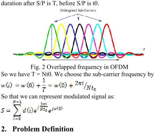
OFDM contributes on the frequency sparing. It picks a gathering of sub-carriers which are orthogonal to each other at the time space, however they are covered in the frequency area, which is deferent from MCM expressed above (ensure no covered in frequency space by monitor). Along these lines, in spite of the fact that they are covered, they are orthogonal to each other and in this manner can be isolated at the beneficiary. We first write out the modulated signal as:
where is the frequency of sub-carrier i. Suppose the time duration after S/P is T, before S/P is t0.
Fig. 2 Overlapped frequency in OFDM
So we have T = Nt0. We choose the sub-carrier frequency by
So that we can represent modulated signal as:
2.
Problem Definition
Wavelet based OFDM is observed to be an effective strategy to supplant FFT based OFDM systems as wavelets have many favorable circumstances when contrasted with FFT-OFDM [9-13]. DWT based OFDM can possibly diminish the equipment unpredictability on the grounds that Cyclic Prefix isn't required for this situation and proposed system gives almost consummate remaking. wavelet is a viable instrument to think about the signals in time frequency joint space as it can give concurrent data about time and frequency, along these lines gives the time frequency portrayal of the flag. It has been discovered that wavelets have minimal restriction in both time space and frequency area and have better orthogonality. Wavelet based OFDM can battle the narrowband interference
as the wavelets have high phantom control properties; making the system more vigorous against inter-carrier interference when contrasted with FFT acknowledgment. As cyclic prefix isn't utilized as a part of wavelet OFDM, the data rates are superior to that of FFT OFDM systems [5]. Wavelet based OFDM is utilized keeping in mind the end goal to expel the utilization of cyclic prefix which diminishes the bandwidth wastage and the transmission control is likewise lessened by the utilization of wavelet transform. The unearthly regulation of the channels in Wavelet-OFDM is additionally superior to the FFT-OFDM. Discrete wavelet transform is a kind of wavelet transform which is observed to be an elective way to deal with supplants IFFT and FFT in OFDM systems.
Fig. 3 DFT based O-OFDM system
Available online: https://edupediapublications.org/journals/index.php/IJR/ P a g e | 1110 and very proficient strategy for disintegration of signals. Be
that as it may, it has been experienced the destruction consider which comes about the loss of data at the season of recreation of the data at the transmitter or beneficiary end, therefore the bi-orthogonal wavelet decomposition (BoWD) is utilized as a substitution for the DWT based OFDM. Above all, we considered the proposed approach in fast optical-OFDM (FO-OFDM) systems which are being used in LTE systems [6] and [7].
3.
Wavelets
Wavelets are especially useful for compressing image data, since a wavelet transform has properties which are in some ways superior to a conventional Fourier transform [8].
x(t)=actual time series, (t)=wavelet function
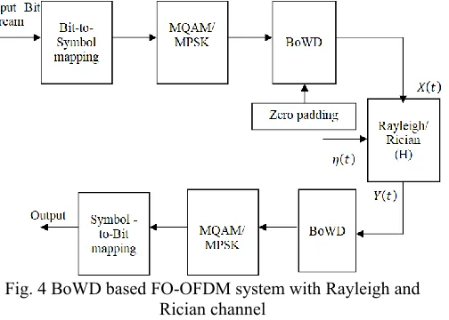
The channel model can be AWGN, Rayleigh or any other channel. To generate an OFDM symbol, the channel encoding of serial data stream is done followed by modulating the symbol using any modulation scheme .To successfully generate OFDM, the relationship among all the carriers must be controlled carefully to sustain the orthogonality of the carriers. Due to this, OFDM symbol is generated choosing the spectrum required firstly, based on the input data, and modulation scheme used. Some data is assigned to each carrier to be produced to transmit. The required amplitude and phase of the carrier is then calculated based on the modulation scheme which is typically differential BPSK, QPSK, or QAM. DWT based OFDM is an efficient approach to replace FFT in conventional OFDM systems. DWT is employed in order to remove the use of cyclic prefix which decreases the bandwidth wastage and the transmission power is also reduced by the use of wavelet transform. The spectral containment of the channels in DWT-OFDM is better than FFT-OFDM. In Wavelet transform, the signal of interest is decomposed into set of basis waveforms, known as wavelets, which provide the way for analyzing the signals by investigating the coefficients of wavelets.
4.
BoWD-OFDM System
BoWD based OFDM is an efficient approach to replace FFT in conventional OFDM systems. DWT is employed in order to remove the use of cyclic prefix which decreases the bandwidth wastage and the transmission power is also reduced by the use of wavelet transform. The spectral containment of the channels in BoWD-OFDM is better than FFT-OFDM as well as DWT-OFDM. In Wavelet transform, the signal of interest is decomposed into set of basis waveforms, known as wavelets, which provide the way for analyzing the signals by investigating the coefficients of wavelets. BoWD is used in several applications and has become very popular among engineers, technologists and mathematicians. The basis
functions of wavelet transform are localized both in time and frequency and possess different resolutions in both domains which makes the wavelet transforms a powerful tool in various applications. Different resolutions correspond to analyze the behavior of the process and the power of the transform. Due to these properties, the wavelets and wavelet transform find their applications in various fields such as data compression, image compression, radar, computer graphics and animation, astronomy, human vision, nuclear engineering, acoustics, biomedical engineering, music, seismology, turbulence, magnetic resonance imaging, fractals and pure mathematics. Since wavelet transform has many advantages such as flexibility, lesser sensitivity against channel distortion and interference as well as better utilization of spectrum, it has been proposed to design the sophisticated wireless communication systems. Wavelets are beneficial in various aspects such as channel modelling, data representation, transceiver design, and source and channel coding, data compression, interference minimization, energy efficient networking and signal de-noising in wireless communication systems. BoWD is known as a flexible and highly efficient method for decomposition of signals. Since wavelet transform has many advantages such as flexibility, lesser sensitivity against channel distortion and interference as well as better utilization of spectrum, it has been proposed to design the sophisticated wireless communication systems. BoWD is known as a flexible and highly efficient method for decomposition of signals.
Fig. 4 BoWD based FO-OFDM system with Rayleigh and Rician channel
A. Bi-orthogonal Wavelet Decomposition (BoWD)
Bi-orthogonal wavelet decomposition is very much utilized for multi resolution analysis because of its multi scaling functionality i.e., two scaling functions to generate wavelet channel banks for disintegration and remaking separately. It will give more viable disintegration coefficients because of its multi scaling property.
In the case of orthogonal, we have one hierarchy of
approximation spaces and an orthogonal
decomposition
(1)
T e j tdt
s t t x s
W
0 ( ). .
) ,
Available online: https://edupediapublications.org/journals/index.php/IJR/ P a g e | 1111
which leads us to use two filter sequences and for
decomposition and reconstruction. Hence, we need to construct two different wavelet functions and two different scaling functions.
Let , . Then we will say that the two
sequences are biorthogonal.
Now, our aim is to build two sets of wavelets
(2)
(3)
To do so, we need four filters i.e., two sequences to
be act as decomposition sequences and two sequences as reconstruction sequences. For example, if is a data set, it will be decomposed as follows:
(4)
(5)
And the reconstruction is given by
(6) We can achieve perfect reconstruction by following some conditions given below:
,
Now consider that and are two scaling function
with their own hierarchy of approximation spaces, then we will generate function of wavelet in a method of analogous to the orthogonal case. We now define the scaling function as follows:
(7)
(8) So, finally the bi-orthogonal wavelet functions can be defined as follows:
(9) (10)
B. Rayleigh Distribution
Rayleigh fading is a rational model, when an environment that consists of many objects can scatter the transmitted signal before the arrival of signal at receiver. The central limit theorem holds that, the channel impulse response can be modelled well as a Gaussian process irrespective of individual components distribution when there are enough much scatter. When we apply Central Limit Theorem (CLT) to the large number of paths, then each path can be modelled with time as the variable as circularly symmetric complex Gaussian random variable (GRV), which is known as Rayleigh channel model. When there is no prevalent component to the scatter such model will have the mean of zero and the phase between 0 and 2π radians. Therefore the channel response envelope is Rayleigh distributed. A circularly symmetric complex GRV is of the form,
where the real and imaginary parts are zero mean i.i.d. GRV’s. For circularly symmetric complex random variable,
A circularly symmetric complex GRV is completely specified by the variance
The magnitude , which has the PDF of , is called as
Rayleigh random variable
C. Rician Channel Distribution
It occurs when a transmitted signal will deviate from its normal path and cancels itself automatically. It is a non-deterministic model. The transmitted signal can arrive at the receiver end by several different paths, and at least there is change in one path. When the path is much stronger than the others, typically a line of sight (LoS) signal is known as Rician fading (RF). In this, a Rician distribution is used to characterize the gain of the amplitude. When there is no LoS path between the transmitter and the receiver of OFDM then
the Rayleigh fading can categorize the RF.RF can be defined
by two parameters known as and Ω. Parameter is called a Rise factor and it is defined as the ratio between the direct paths power to the other scattered paths power. And the Ω is the total power of both paths, which can acts as a scaling factor for the Rician distribution. The resulting PDF is then given by,
Where the is the order modified Bessel function of first kind. If the value of is zero then the RF envelope will produced down to the Rayleigh faded envelope.
5.
Performance Evaluation
Simulations have been done in MATLAB 2014a version with 4 GB RAM. We tested the conventional and proposed OFDM systems with various QAM modulation levels that are used for the LTE. Modulations that could be used for LTE are 4 QAM, 16 QAM and 32 QAM (Uplink and downlink). For the purpose of simulation, signal to noise ratio (SNR) of different values are introduced through AWGN, RAYLEIGH, RICIAN channel. Data of 10,000 bits is sent in the form of 100 symbols, so one symbol is of 100 bits.
Table I Simulation Parameters
Parameters Specifications
FFT & IFFT size 64
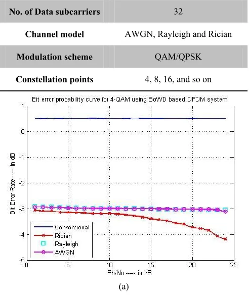
Available online: https://edupediapublications.org/journals/index.php/IJR/ P a g e | 1112 No. of Data subcarriers 32
Channel model AWGN, Rayleigh and Rician
Modulation scheme QAM/QPSK
Constellation points 4, 8, 16, and so on
(a)
(b)
(c)
Fig. 5 BER performance of proposed and conventional system with (a) 4-QAM (b) 16-QAM and (c) 32-QAM under AWGN, Rayleigh
and Rician channels
Fig. 6 Analysis of BER for DFT-OFDM and BoWD-OFDM with various modulation schemes
Averaging for a particular value of SNR for all the symbols is done and BER is obtained and same process is repeated for all the values of SNR and final BERs are obtained. Figure 5 demonstrated that the comparative analysis of BER with respect to signal to noise ratio (SNR) for the conventional OFDM and proposed system under AWGN, Rayleigh and Rician channel distributions. Fig 5(a), (b) and (c) show that the 4-QAM, 16-QAM and 32-QAM respectively. In all the three figures we can observe that the BER value of proposed BoWD-OFDM system with Rician channel obtained lesser values compared to the conventional schemes. This figure shows the relationship between BER and SNR. The values of SNR are from 0 db to 25 db and the scale of SNR is linear. Figure 6 show that the analysis of BER with various modulation schemes for conventional and proposed systems. We can see that while increasing the modulation constellation point the BER get reduced further.
Available online: https://edupediapublications.org/journals/index.php/IJR/ P a g e | 1113 In this article, we had given an analysis of bit error rate in
FO-OFDM for LTE networks. We utilized BoWD for spectral efficiency enhancement, which offers excellent bandwidth utilization over large number of users. Thus, the performance of the system has been improved in terms of bit error rate. We also compared our proposed system with conventional OFDM systems such as optical-DFT-OFDM under AWGN, Rayleigh and Rician channel distributions with different modulation techniques like M-QAM by varying M=4, 16, 32 and so on. Further, our system can be improved by implementing hybrid wavelet approaches which will extensively enhance the system spectral efficiency.
7.
References
[1] R.W. Klein, M.A. Temple, R.A. Raines, and R.L.
Claypoole Jr., “Interference Avoidance
Communications Using Wavelet Domain
Transformation Techniques”, IEEE Electronic Letters, vol. 37, no. 15, pp. 987–989, 2001.
[2] G. Gowri, G. Uma Maheswari, E. Vishnupriya, S. Prabha, D. Meenakshi, N. R. Raajan, “Performance Analysis of DWT-OFDM and FFT-OFDM systems”, International Journal of Engineering and Technology (IJET), vol. 5, no. 2, 2013.
[3] Swati Sharma, Sanjeev Kumar, “BER Performance
Evaluation of FFT-OFDM and DWT-OFDM”, International Journal of Network and Mobile Technologies, vol. 2, issue 2, pp. 110-116, 2011.
[4] Rohit Bodhe, Satish Narkhede, Shirish Joshi,
“Design of Simulink Model for OFDM and Comparison of FFT-OFDM and DWT-OFDM”, International Journal of Engineering Science and Technology, vol. 4, no. 5, pp. 1914-1924, 2012.
[5] P. Gotz, U. Jorn , K. Werner, Z Georg, “A
comparison of various MCM schemes”, 5th International OFDMworkshop, Hamburg, Germany, pp. 20-1 – 20-5, July 2000.
[6] “LTE in a nutshell: The physical layer”, white paper, 2010, http://www.tsiwireless.com.
[7] R. Mika, T. Olav, “LTE, the radio technology path toward 4G”, omputer communications, Elsevier, vol. 33, no. 16, pp. 1894-1906, Oct. 2010.
[8] Broughton SA, Bryan K. Discrete Fourier analysis and wavelets. New Jersey, John Wiley, 2009.
[9] K. A. Hasan, M. Waleed A., N. Saad, “The
performance of multi wavelets based OFDM system under different channel conditions”, Digital signal processing, Elsevier, vol. 20, no. 2, pp. 472- 482, March 2010.
[10]G. M. Kumar, S. Tiwari, “Performance evaluation of
conventional and wavelet based OFDM system”,
International journal of electronics and
communications, Elsevier, vol. 67, no. 4, pp. 348-354, April 2013.
[11]M. Petri , J. Antony, “Wavelet packet modulation for wireless communication”, Wireless communication
& mobile computing journal, vol. 5, no. 2, pp. 1-18, March 2005.
[12]L. M. Kumar, N. Homayoun, “A review of wavelets
for digital wireless communication”, Wireless
personal communications, Kluwer academic
publishers- Plenum publishers, vol. 37, no. 3-4, pp. 387-420, May 2006.
[13]O. Eiji, I Yasunori, I Tetsushi, “Multimode
transmission using wavelet packet modulation and OFDM”, IEEE vehicular technology conference, vol. 3, pp. 1458-1462, Oct. 2003.
AUTHOR BIOGRAPHY
Angotu Tejaswi doing her M. Tech (C & SP) in PNC & Vijai Institute of Technology, Repudi, Guntur, AP. Her area of interests is signal processing, wireless networks and communication
Prof. S. H. V. Prasada Rao working as principal in P.N.C. & Vijai Institute of Engineering and Technology, Repudi, Phirangipuram, Guntur(dist). He received his B. Tech degree in
Electronics and Communication