ISSN (Print) : 2320 – 3765 ISSN (Online): 2278 – 8875
I
nternational
J
ournal of
A
dvanced
R
esearch in
E
lectrical,
E
lectronics and
I
nstrumentation
E
ngineering
(An ISO 3297: 2007 Certified Organization)
Vol. 5, Issue 8, August 2016
SIMULINK Model for Sensorless Control of
Three Phase BLDC Motor Driver System
Rashmi Soni1, Neelesh Kumar2
PG Student, Dept. of EEE, Disha Institute of Tech. and Management, Raipur, Chhattisgarh, India1
Assistant Professor, Dept. of EEE, Disha Institute of Tech. and Management, Raipur, Chhattisgarh, India2
ABSTRACT: This paper presents a simulation for sensorless control of three phase motor driver system. Here the actual speed of BLDC motor is compared with the reference speed and the error signal thus produces, regulates the speed controller. PI controller as speed regulator generates the signal and this signal produces the trigger angle control signal accordingly. This BLDC motor is in a wide use today in various industries so it is very important to improve its efficiency. This method improves speed regulation, reduce torque ripple as well as help in power control, provide a smooth and fast startup to the motor drive system. So here present a paper which shows the improvement in BLDC motor with power and torque control.
KEYWORDS: BLDC motor, sensorless control, PI controller, voltage regulator, simulation.
I. INTRODUCTION
The mechanical commutator of bushed DC motor is replaced by electronic switches which supply current to the motor windings as function of rotor position. The BLDC motor employs a DC power supply switched to the stator phase windings of the motor by power devices the switching sequence being determined by rotor position. The phase current of BLDC motor is typically rectangular shape and synchronized with back EMF to produce constant torque at constant speed. These brushless DC motors are generally controlled using three phase inverter, requiring a rotor position sensor for starting and for providing proper commutation sequence to the inverter. The control of BLDC motor can be done in sensor or sensorless mode, but to reduce overall cost of actuating devices, sensorless control technique is normally used. Sensorless operation of a brushless dc (BLDC) motor using the back EMF information (electromotive force), such as back EMF zero crossing, is one of the methods. However, at standstill or at low speeds, it is impossible or very difficult to estimate the position of the rotor by using the back EMF method.
In order to measure the stator inductance that varies with rotor position, a number of voltage pulses are applied periodically to the motor. Since the applied voltage pulses make the system inefficient, these methods are not adequate. A popular method to estimate the initial rotor position at standstill is to utilize the saturation effect of the stator iron core because it acts as a permanent magnet. The inductance of the stator winding has its minimum value where the north pole of the rotor magnet lies in the corresponding stator winding axis. To make the system more reliable control loops and angle control system is used in this project. This method improves speed regulation, reduce torque ripple as well as help in power control, provide a smooth and fast startup to the motor drive system.
II. RELATED WORK
Analysis Of BLDC Motor Drive System
In a BLDC motor, the trapezoidal back EMF implies that the mutual inductance between stator and rotor is non sinusoidal, thus transforming to d-q axis does not provide any particular advantage, and so abc phase variable model is preferred. In the present model, the motor is assumed to be star connected with isolated neutral. The analysis is based on the following assumptions:
1. The motor is not saturated.
ISSN (Print) : 2320 – 3765 ISSN (Online): 2278 – 8875
I
nternational
J
ournal of
A
dvanced
R
esearch in
E
lectrical,
E
lectronics and
I
nstrumentation
E
ngineering
(An ISO 3297: 2007 Certified Organization)
Vol. 5, Issue 8, August 2016
=− + ………1
= [Vca + 2Vcb – 3Rib +(ea + ec – 2eb)]/3Lt………...2
= [Vca - Vbc – 3Ric +(ea + eb – 2ec)]/3Lt………..3
Ek = ∑ ( )………...………...………...4
And the electromagnetic torque can be express as, TL – Te = J(dwm/dt) + Bwm……….5
And electrical rotor speed and position are related by θ = P*wm/2……….6
Ke is torque constant. = + ( + ) ⎣ ⎢ ⎢ ⎢ ⎡ ⎦ ⎥ ⎥ ⎥ ⎤ + ……….7
The back EMF is a function of rotor position (θr) and has the amplitude E = Ke ωm(Ke is the back EMF constant). PI controller Conventional PI controller is used as a speed controller for recovering the actual motor speed to the reference. The reference and the measured speed are the input signals to the PI controller. The KPand KIvalues of the controller are determined by trial and error method for set speed. The controller output is limited to give the reference torque, its integral term has the effects of accumulation, memorization and delay, which enables PI controller to remove static error. The Saturation block limits the amplitude of outputting three phase reference current to the demanding range. The differential term can effectively reduce the overshoot and maximum dynamic deviation. The standard PI controller calculates the deviation e(t) between the reference value and the actual value. Then, the plant is controlled by the variable u(t) with a linear combination of proportional–integral terms. The corresponding PI control law in continuous form can be expressed as u(t) = KPe(t)+KI ∫ ( )dt………8
where,
KP = proportional gain;
KI = integral gain;
T = integral time constant.
During the design of a BLDC motor speed controller, it is essential to consider the system’s working environment, load characteristics and position-detection methods. The target of control is to achieve wide speed range, small static tracing error, good tracking performance and anti-disturbance ability. For a PI controller, one tuning method is first to set the integral part to zero, then increase the proportional part until the system response is stable, finally tune the integral part to improve the dynamic response ability and static stability.
Voltage regulator
The voltage regulator is a circuit that keeps a set constant voltage across its load despite changes in load, temperature and power supply. A voltage regulator may be either of AC type or DC type. A voltage regulator generates a fixed output voltage of a present magnitude that remains constant regardless of changes to its input voltage or load condition. It may use an electromechanical mechanism or electronic component. Depending on the design it may be used to regulate one or more AC or DC voltages.
ISSN (Print) : 2320 – 3765 ISSN (Online): 2278 – 8875
I
nternational
J
ournal of
A
dvanced
R
esearch in
E
lectrical,
E
lectronics and
I
nstrumentation
E
ngineering
(An ISO 3297: 2007 Certified Organization)
Vol. 5, Issue 8, August 2016
A switching regulator rapidly switches a series device on and off. Switching regulators are more efficient because the series element is either fully conducting or switched off. Switching regulators require a means to vary their output voltage in response to input and output voltage changes. One approach is to use PWM that controls the input to the associated power switch which controls its ON and OFF time (duty cycle). In operation the regulator’s filtered output voltage is feedback to the PWM controller to control the duty cycle. If the filtered output tends to change, the feedback applied to the PWM controller varies the duty cycle to maintain a constant voltage output. The PWM generator block generates pulses for carrier based PWM converters. The block can be used to fire the forced commutated devices like IGBT of single phase, two phase, three phase or two level bridges.
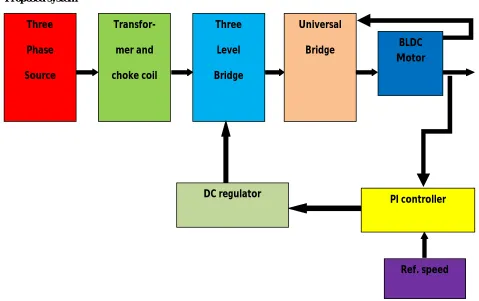
Proposed system
Fig 1: block diagram of the proposed system
Three phase source
Three phase source is a electric power generation, transmission and distribution system and is most commonly used by electrical grids worldwide to transfer power. It is also used to power large motors and heavy loads. A three phase power system is more economical than an equivalent single phase at the same line to ground voltage because it uses less conductor material to transmit electrical power.
In a symmetric three phase power supply system, three conductors each carry an alternating current of the same frequency and voltage amplitude relative to common reference but with a phase difference of one third of the period. Due to the phase difference the voltage on any conductor reaches its peak at one third of a cycle before the remaining conductor. This phase delay gives constant power transfer to a balanced linear load. It also makes it possible to produce a rotating magnetic field in an electric motor.
Transformer and choke coil
A transformer is a static device which consists of two or more stationary electric circuit interlinked by a common magnetic circuit for the purpose of transferring electrical energy between them. The principle of transfer is electromagnetic induction. The transfer of energy from one circuit to another takes place without a change in
Three
Phase
Source
Transfor-
mer and
choke coil
Three
Level
Bridge
Universal
Bridge BLDC
Motor
PI controller
ISSN (Print) : 2320 – 3765 ISSN (Online): 2278 – 8875
I
nternational
J
ournal of
A
dvanced
R
esearch in
E
lectrical,
E
lectronics and
I
nstrumentation
E
ngineering
(An ISO 3297: 2007 Certified Organization)
Vol. 5, Issue 8, August 2016
frequency. There are step up and step down transformers which either increases the magnitude of the voltage of supply or either decreases the magnitude of voltage of the supply.
A choke coil is a series connection of inductor and resistor used to block higher frequency alternating current in an electrical circuit while passing lower frequency or direct current. A choke usually consists of a coil of insulated wire often wound on a magnetic core. The choke’s impedance increases with frequency. Its low electrical resistance passes both AC and DC with little power loss, but it can limit the amount of AC due its reactance.
Three level bridge
The three level bridge here is an AC to DC converter consists of three phase IGBT based voltage source converter. The converter is pulse width modulated to produce a constant DC voltage. The VSC is controlled in a closed loop by dc regulator at a certain angle it is triggered as the pulse is generated. So the magnitude of the voltage varies with the trigger. The bridge works when a pulse from DC regulator is given to the block. But after certain time the stop pulsing signal is activated and pulse normally sent to converter are blocked. When the pulses are blocked three level bridge block operation becomes similar to a three phase diode bridge.
Universal Bridge
The universal bridge implements a three phase power converter that consists of up to six power switches (MOSFET) connected in a bridge configuration. The bridge acts as an inverter which changes the DC voltage of input to AC voltage output but of variable frequency. The output of universal bridge is fed to the BLDC motor. The frequency changes according to the speed of BLDC motor to reduce the error caused by difference of reference and actual speed. The speed of the motor is sensed by the decoder and gate circuit and it sends a pulse to the universal bridge. Then according to this signal the bridge changes the frequency to compensate the difference and to maintain the constant speed.
ISSN (Print) : 2320 – 3765 ISSN (Online): 2278 – 8875
I
nternational
J
ournal of
A
dvanced
R
esearch in
E
lectrical,
E
lectronics and
I
nstrumentation
E
ngineering
(An ISO 3297: 2007 Certified Organization)
Vol. 5, Issue 8, August 2016
III. METHODOLOGY
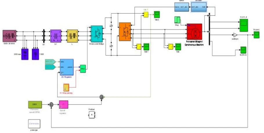
MATLAB and SIMULATION model design
Fig. 2: SIMULINK Model for Sensorless Control of Three Phase BLDC Motor Driver System
IV. SIMULINK RESULTS
ISSN (Print) : 2320 – 3765 ISSN (Online): 2278 – 8875
I
nternational
J
ournal of
A
dvanced
R
esearch in
E
lectrical,
E
lectronics and
I
nstrumentation
E
ngineering
(An ISO 3297: 2007 Certified Organization)
Vol. 5, Issue 8, August 2016
Fig. 4: DC bus voltage Vs time
Fig. 5: Stator current Vs time
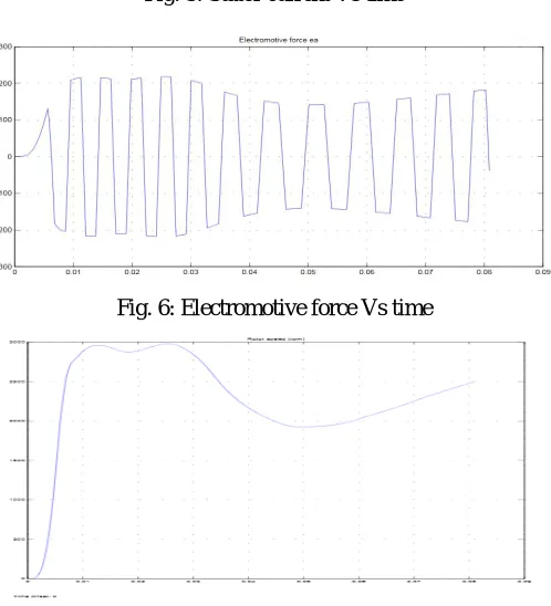
Fig. 6: Electromotive force Vs time
ISSN (Print) : 2320 – 3765 ISSN (Online): 2278 – 8875
I
nternational
J
ournal of
A
dvanced
R
esearch in
E
lectrical,
E
lectronics and
I
nstrumentation
E
ngineering
(An ISO 3297: 2007 Certified Organization)
Vol. 5, Issue 8, August 2016
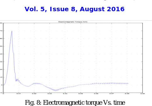
Fig. 8: Electromagnetic torque Vs. time
The simulation results shows that by using this sensorless method, the quadrature stator current (isq) will be increased that, in turn, increases the starting torque by about 14% and 5% compared with the 60° and 30° resolution methods, respectively. In addition, shows that by using the proposed method, the ripple of the quadrature stator current (isq) is reduced significantly. The starting torque ripple is decreased, while the average starting torque is increased. The startup characteristics of the motor by using the proposed sensorless are shown in graph. It is demonstrated that the startup is much faster (about 25%) here.
V. CONCLUSION
The main objective is to investigate the dynamic performance of the motor at different load condition. The non-linear simulation model of the BLDC motor drive system with PI control based on MATLAB/Simulink platform is presented. When the load varies the speed of the motor, power and torque also varies. But for a system to be efficient it is necessary to maintain the speed at constant. The controlling of speed, power and torque is the main objective of this project. The speed is controlled with the help of PI controller. The speed controller regulates the rotor movement by varying the frequency of the pulse based on signal from sensor.
The application of this work is on the basis of simulation and analysis carried out can be to select the proper motor specifications to match the load requirements. The simulation is used to predict the behavior of actual system. These predicted results can be used to determine the range of parameters of controller while designing the system.
REFERENCES
[1] Saxena S.K. and Saha T., “Ultra High Speed Operation of BLDC Motor with Enhanced Motor Dynamics for Space Limited Applications”, IEEE Aerospace Conference, (2012).
[2] Heo H.J. and Im W.S., “Fault Tolerant Control Methods of Dual Type Independent Multi-phase BLDC Motor under Open switch Fault Conditions”, IEEE Annual Applied Power Electr. Conference and Exposition, (February 2012) 1591-1596.
[3] Markovic M. and Hodder A., “An analytical determination of the torque–speed and efficiency–speed characteristics of a BLDC motor”, IEEE (December 2009) 168-172.
[4] Kan K.S. and Tzou Y.Y., “Adaptive Wide Angle PWM Control Strategy of BLDC Motor Drive for Efficiency Optimization and Wide Speed Control Range”, IEEE Energy Conversion Congress and Exposition, (2011) 1721-1727.
[5] Joo J.H., Kim D.H., Sim D.S. and Choi J.K., “Design of a DSP Controller and Driver for the Power-by-wire Driving System with BLDC Servo Motor Pump” IEEE Elect./ Electrn. Engg, Comp., Telecomm., Info. Tech. Conf. (ECTICON), (2011) 573-576.
[6] Hossain S.A. and Reis P., “Effect of BLDC Motor Commutation Schemes on Inverter Power Loss”, IEEE Intenational Conf. on Elec. Machine, (2008).
[7] Xuanfeng S. Xinhyan L., “BLDC motor speed servo system based on novel P-fuzzy self-adaptive PID control” IEEE Intrenational Conf. on Info., Networking And Automation (ICINA), (2010) 186-190.
[8] Bharatkar S.S., Yanamshetti R., Chattereji D. and Ganguli A.K., “Performance Comparison of PWM Inverter Fed IM Drive & BLDC Drive for Vehicular Applications”, IEEE ICVES, (2009) 125-129.
[9] Kim T., Kim C. and Lyou J., “A New Sensorless Drive Scheme for a BLDC Motor Based on the Terminal Voltage Difference”, IEEE Intenational Conf. on Indus. Electr. Society, (2011) 1710-1715.
[10] Xiaofeng Z. ,Zhengyu L., “A New BLDC Motor Drives Method Based on BUCK Converter for Torque Ripple Reduction”, IEEE International Power Electr. And Motion Control (IPEMC), (2006).