International Journal of Research (IJR)
e-ISSN: 2348-6848, p- ISSN: 2348-795X Volume 2, Issue 10, October 2015Available at http://internationaljournalofresearch.org
Android Smart Phone and Thermal Printer based
Restaurant Menu Ordering System
K. Sri SasiKala
Assistant Professor,CVR College of Engineering,Hyderabad,Telangana Abstract: —
The growing number of restaurants and population of restaurant-goers have emphasized the need to enhance the working of hospitality industry. This research work aims at improving the quality of services and business of the hospitality industry by incorporating technology. A detailed research on the integration and utilization of technology in hospitality industries showcased that various applications based on wireless technologies are already in use enabling partial automation of the food ordering process. In this paper, we discuss about the integration of Android technology in restaurants using thermal printer and Wi-Fi. The mobile at the customer table contains the android application with all the restaurant and menu details. The customer mobile, kitchen display and the thermal printer at cashier counter connects directly with each other through Wi-Fi. This wireless application is user-friendly, improves efficiency and accuracy for restaurants by saving time, reduces human errors and provides customer feedback. This system successfully overcomes the drawbacks in earlier automated food ordering systems and is less expensive as it requires a one-time investment for gadgets.
Keywords: Thermal Printer; Wi-Fi; PIC; LCD; Android APP
I.INTRODUCTION:
The smart ordering system is proposed with the use of a handheld tool which is used to make an order at the restaurant. It is proposed to solve the problems which are faced by the restaurant’s entrepreneur in the attempt to organize the restaurant more efficiently skilled and capable. The system uses a small keyboard which is placed on each table for the customer to make orders. Order is made by inserting the menu code on the small keyboard. This code comes together with the menu. A signal will be sent to the order
section by Wi-Fi communication, and
automatically will be displayed on a LCD screen in the kitchen. The project will reduce time to be spent on making the orders and paying the bills, whereby the cost and man power also can be optimized.
The advancement in information and communication technology (ITC) has greatly influenced the business transactions. The adoption of wireless technology & emergence of mobile devices has led to automation in the hospitality industry. Business in hospitality industry such as restaurants can be improved with the combination of wireless and mobile technologies. The
competition in restaurant business has increased with the advancements in food ordering techniques [1].
The project started with reviewing several sources as the literature review. The company of GeneralSoft Ltd, Silwood Business Centre had proposed “The SMART System” [2]. They proved that by using this SMART system, it will guarantee not only improve of customer efficiency. By using the SMART system and its technologies restaurant will improve their company speed and accuracy.
International Journal of Research (IJR)
e-ISSN: 2348-6848, p- ISSN: 2348-795X Volume 2, Issue 10, October 2015Available at http://internationaljournalofresearch.org
their Malaysian Delight application. The number of access points will depend on the restaurant’s size and the number of PDAs used by the waiters [3].
Based on the all literature reviewed, the proposed project came with the aim to build one ordering and delivering system at restaurants
using keypad, display screen and Bluetooth communication. Further, the hardware and software need to be working and functioning synchronously. For this purposed, a circuit of PIC microcontroller with connection to the both transmitter and receiver need to be designed in order to control instructions the whole system.
II. MATERIALS & METHODS: The methodology used will be divided into two parts as system design and system process flow.
A. System Design: The operation of the whole system can be seen through the block diagram. The Fig. 1 below shows the project
block diagram. Android application is used as the input and LCD display is used as the output in kitchen section and thermal printer is used for billing purpose at counter section for the system design.
.
Block Diagram
Filter
O/P 5V DC I/O
230V
Transforme r
Rectifier Regulator
Regulated power supply
LED indicators
Crystal oscillator
LCD driver circuit
LCD
Wi-Fi module
Thermal Printer
Wifi Enabled
Mobile
Reset
B. System Process Flow
Start
Customer chooses Menu
Customer Orders the Menu based through Wi-Fi
Controller receives data via Wi-Fi receiver
Micro controller processes the data
Bill is printed using thermal printer The processed data will be
sent to counter for billing
The menu will be Displayed in kitchen section
The processed data sent to kitchen section for
ordering process
Finish
International Journal of Research (IJR)
e-ISSN: 2348-6848, p- ISSN: 2348-795X Volume 2, Issue 10, October 2015Available at http://internationaljournalofresearch.org
to make orders. Firstly, customer needed to choose their menu. Order is made by selecting the in the menu list...
Then, the ordered data is sent to the microcontroller via Wi-Fi receiver. The microcontroller will continuously receive data via Wi-Fi receiver module. The data is processed by the microcontroller when it received signal from Wi-Fi communication. The processed data is to be sent to the kitchen LCD display for ordering
purpose, and to the counter section thermal printer for billing process. This system will be done after the customer completed their orders.
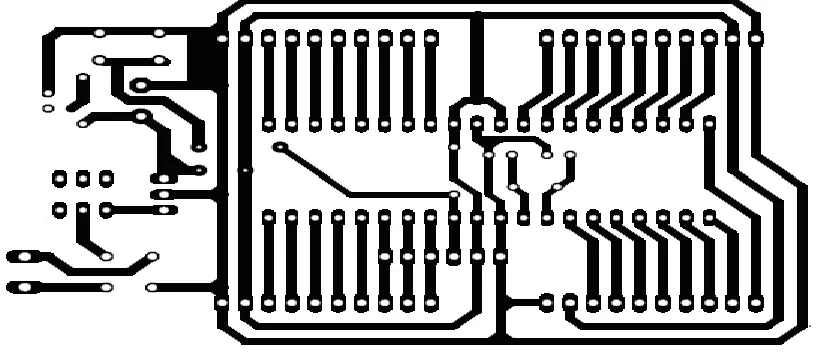
C. Circuit Construction Process All the circuits have been combined to form a complete whole system circuit. The circuit has been design using software Protel. Then circuit is designed for Printed Circuit Board (PCB).
Fig 3 Fig.3 Circuit by Using Protel After all the
error in the schematic designed is corrected; layout for a PCB is constructed. A constructed layout will be simulated in order to know either the circuit requires jumper or it can works on its own at the real circuit. Besides providing layout on PCB, location of the other component can be predetermined for the actual circuit.
Circuit will be ironed at the PCB which has been cut according to suitable the size of the circuit. Finally, component is soldered to the board and the circuit is ready to be powered up, tested and used.
D. Software Development
For the software development we are using Embedded C language for writing the code and for compiling PIC C compiler and Proteus software to convert the code into hex file and program into the micro controller.
III. RESULTS/FINDINGS AND
DISCUSSION Testing is conducted to evaluate the capacity, functions and effectiveness of the developed application. Information about the results and analysis are based on functionality and implementation process.
International Journal of Research (IJR)
e-ISSN: 2348-6848, p- ISSN: 2348-795X Volume 2, Issue 10, October 2015Available at http://internationaljournalofresearch.org
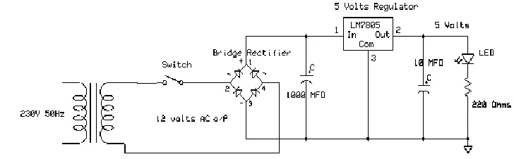
B. Power Supply of the
Microcontroller Based on Fig. 4 below, suitable components was used to convert from
230v AC to 5V DC. From following circuit that had been conducted, voltage regulator that was used will steps down high voltage 12V to low voltage 5V. For this project, its need To use 5V DC
Fig. 4 Voltage Regulator 5V Circuit
C. Microcontroller: The microcontroller used in this project is the Microchip PIC16F877A. This controller has 33 inputs and outputs. The input and output for the microcontroller can be used in any combination. All input and output are connected to the outside world through the registers which are called port. For this microcontroller, it has 5 ports which are PORT AE. PORT A has 6 bits while each of PORT B, C and D has 8 bits. Only PORTE has 3 bits.
E. Final Project:
IV.CONCLUSION AND FUTURE SCOPE: As a
conclusion, this hardware and software of project is successfully functioned as the objectives of the project. This project solved the problem which is faced by the restaurant’s entrepreneur in the attempt to organize the restaurant more efficiently skilled and capable. It is also can be used to reduce the lateness and the error on ordering foods by the customer’s by restaurant. By using this system, there are no more complaints about the services. This project can contribute to the advancement of science and technology by having upgrading GSM through which he will receive message of each order. He can sit any where and can monitor the
restaurant without getting any wrong economical information.
In next phase, we will be working on providing provisions to accept different types of payments like checks, credit cards, debit cards, tips, etc. The system can be further extended to register and link multiple restaurants to enhance the dining experience of customers.
REFERENCES
[1] T.P. Liang, et al., ”Adoption of mobile technology in business- a fitviability model”, Industrial Management & data systems, vol . 107, pp. 1154-1169, 2007.
[2] (2013) Smart System Website. [Online].
Available :
http://www.smartsystems.co.uk/smartsystem
s/kbbconnect
International Journal of Research (IJR)
e-ISSN: 2348-6848, p- ISSN: 2348-795X Volume 2, Issue 10, October 2015Available at http://internationaljournalofresearch.org
nline/archive/mba200307a/ mba_erm200307.htm
[4] (2009) LRS Restaurant Server Pager. [Online]. Avalable : http://www.foodsoftware.com
[5] (2013) FLIR Customer Support Center.
[Online]. Available :
http://flir.custhelp.com/app/answers/detail/a_id/305
[6] Iovine, J. (2000), “PIC Microcontroller Project Book.” Washington, C.D: McGraw-Hill.
[7] (2013) PIC 16F877, Data Sheet Module. MICROCHIP INC. Technical support user guide. [Online]. Available: http://www.microchip.com.
[8] (2013) http://www.fiacopetti.it
[9] (2013) Electronics Lab.com. [Online]. Available :http://www.electronicslab.com/blog/?tag=microcon troller?〈 =en_us&output=json