Microcontroller Based Protection System for
Automobiles
R.Jesurani1, E.Meenakshi2, S.Kokila 3, A.Nivetha4, S.Parthasarathy 5
U.G. Student, Department of Electrical and Electronics Engineering, New Prince Shri Bhavani College of Engineering
and Technology, Gowrivakkam, Chennai, India1,2,3,4
Associate Professor, Department of Electrical and Electronics Engineering, New prince Shri Bhavani College of
Engineering and Technology, Gowrivakkam, Chennai, India 5
ABSTRACT: Presently when it comes to road safety and preventing accidents, there are never enough ways to try to
reduce the number of casualties that result each year from road accidents. A variety of methods are continually being developed that try to improve road conditions, car safety and technology to help combat unsafe roads and drivers. With statistics suggesting that around 95% of accidents are caused by driver error, it’s not surprising that technology is continually being developed to give our cars more control over any driving that we do. New vehicle technology aims to help drivers by assisting in an emergency situation, informing the driver of possible hazards . Thus the main aim of our project is to control the accident by sensing the distance of the vehicle and person’s heartbeat and processing through microcontroller to stop the car from accident. These process are carried out automatically.
KEYWORDS: Ultrasonic sensor, Heartbeat sensor, Sleeping detector, PIC microcontroller.
I. INTRODUCTION
New vehicle technology aims to help drivers by assisting in an emergency situation, informing the driver of possible hazards and in some cases even removing driver control altogether. Large automobile companies such as Mercedes-Benz have looked into the various stages of accidents and conclude that with their Integrated Safety Concept, they could improve the critical ‘accident’ stage where people are injured. They believe that by improving technology present in cars, there are ways of providing drivers with enough information to avoid road accidents before they occur. They, along with other manufacturers such as Lexus include an early warning system in some of their cars that features radar guided pre-crash technology to brace the car for any possible hazard it senses. These road systems are not just based in the future, they’re very present right now in many top of the range cars and along with stability control, anti-rollover systems, ABS brakes and more, cars are making the correct step forward into reducing accidents. Along with these technologies we go for a new technology that works automatically during emergency situations.
II. EXISTING SYSTEM
i) EYE BLINK SENSOR
Vehicles accidents are most common if the driving is inadequate. These happen on most factors if the driver is drowsy or if he is alcoholic drive drowsiness is recognized as an important factor in the vehicle accidents. This helps in controlling accidents due to unconsciousness through eye blink .Here Eye blink sensor is fixed in vehicle where if driver loses consciousness, then it indicate through alarm.
ii) ALCOHOL DECTION SYSTEM
iii) PARKING SENSOR
Parking sensor is another technique to avoid collision with the backside vehicles while parking. To stop the vehicle without any accidents we are in need of a system to stop the vehicle with high precision to safety for that IR sensor was used as parking sensors.
III. PROPOSED SYSTEM BLOCK DIAGRAM
Fig. 1. Block Diagram
IV. INPUTS
i)ULTRASONIC SENSOR
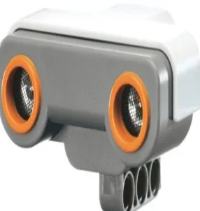
The ultrasonic sensor is a device you can use with the microcontroller to measure how far away an object is. With a range of 3 centimeters to 3.3 meters, it's a shoe-in for any number of robotics and automation projects. It's also remarkably accurate, easily detecting an object's distance down to the half centimeter.
Fig. 2. Ultrasonic sensor
ULTRASONC SENSOR
HEART BEAT SENSOR
SLEEPING DETECTOR
MICROCONTROLLER
BUZZER LCD RELAY
DRIVER
RELAY DRIVER
RELAY RELAY
CLUTCH CONTROLLER
a)WORKING OF ULTRASONIC SENSOR
Fig.3. Working of ultrasonic sensor
Figure shows how the sensor sends a brief chirp with its ultrasonic speaker and makes it possible for the microcontroller to measure the time it takes the echo to return to its ultrasonic microphone. The microcontroller starts by sending the ultrasonic sensor a pulse to start the measurement. Then, the ultrasonic sensor waits long enough for the embedded c program to start logic 1command. At the same time the ultrasonic sensor chirps its 40 kHz tone, it sends a high signal to the microcontroller. When the ultrasonic sensor detects the echo with its ultrasonic microphone, it changes that high signal back to low. The embedded c logic highcommand stores how long the high signal from the sensor lasted in a variable. The time measurement is how long it took sound to travel to the object and back. With this measurement, you can then use the speed of sound in air to make your program calculate the object's distance in centimeters, inches, feet, etc...
2)HEARTBEAT SENSOR
A heart rate sensor consists of a simple device that can receive a signal in the form of a pulse rate and calculate the heart beat signal in beats per minute. A normal human heartbeat is about 70 beats per minute for adult males and 75 beats for adult females. Many conditions affect heart rate. A normal heartbeat condition is called bradycardia and an abnormal heartbeat condition is called tachycardia. Heart rate sensor method is also used to measure the pulse rate. If the detected pulse level is found to be abnormal, an amplified signal is fed to the controller. After receiving the signal, the controller checks the strength. An abnormal pulse rate usually means a high pulse rate. When this is found to be the case, the vehicle slows down and comes to a halt. The pulse oximeter detects the pulse of the driver then it is feed in to the microcontroller and it can also be displayed at the display screen (LCD).
a)LIMITATIONSOF EXISTING HEARTBEAT SENSOR
Since there is no assurance for the placement of finger on the steering arm sometimes the heart rate cannot be sent. In that case only the position of latitude and longitude will be sent in order to identify the location of the accident and not the heart rate of the victim.
b) PROPOSED TECHNIQUE
In order to overcome the above limitation the heart rate sensor can be placed in the seat belt where it will be in continuous contact with the person. In that case the heart rate of the person can be sent continuously to the medical team, say every 10secs,to monitor the victim continuously. This will be effective for others who are in the car too. Chest strap type heart beat sensors are used to make this project more effective.
Fig.5. Chest strap type heartbeat sensor 3)SLEEPING DETECTOR
Also called as an Ideal switch. It is a kind of a switch which can be fixed on the steering where one often uses his/her hands. It can be used to monitor whether the driver is awake or not. The switch should be pressed for every 2min if not buzzer sound is given for alert and the vehicle de-accelerates automatically and stops the car by itself protecting the person as well as the vehicle from danger.
V. WORKINGOF MICROCONTROLLER
In the stopping operation the microcontroller will activate two different networks namely Brakes and Fuel injection system. If the ultrasonic sensor detects any obstacle within a safe distance then the speed of the vehicle will not be came down to zero instead of that the speed will brought down in a slower manner if there is no object then the speed can be brought down in quick way in which the passengers doesn’t get affect.
VI. CIRCUIT DIAGRAM
Heart Beat Sensor VCC (+5V) 4.7K Fuel Valve 10K 13 2 VCC (+5V) BC547 24 4.7K 17 13 1K 6 VCC (+5V) 104 6 LED1 19 10K 23 VCC (+12V) -+ U1A LM358 3 2 1 8 4 18 11 ULTRASONIC SENSOR IN4007 LED 22 VCC (+12V) 15 0.1MDF 560E 3 RELAY Trigg 16 Fuel Valve RELAY 27 100MFD\25V Echo 5 4.7K 1 P IC 1 6 F 7 2 LED1 + 12 IN4007 25 BC547 28 IC7805 4 +5V 1K 2 VCC (+12V)
16X2 LCD Display
10K 3 11 D1 + 20 VCC (+5V) 1K 10MFD Vehicle Battery 14 12 1 1000MFD\50V 15 BUZZER BC547 Sleeping Detection Sensor 16 Fig.7.Circuit diagram VII. RESULTS 1)LCD
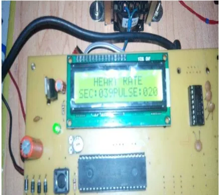
The LCD is used to display the distance, heart rate and also whether the person has normal or abnormal heartbeat.The pulse oximeter or heartbeat sensor detects the pulse of the driver then it is feed in to the microcontroller and it can also be displayed at the display screen (LCD).
2)BUZZER
PIEZOELECTRIC SOUNDER AND BUZZER
Fig.8.Buzzer
A buzzer or beeper is a signaling device, usually electronic, typically used in automobiles, household appliances such as a microwave oven, or game shows.In this project,buzzer is used during emergency situation to give alert to the driver. It sounds under three conditions:
When the ultrasonic sensor detects some objects in front of the vehicle.
When heartbeat sensor’s output is low or high than the normal value.
When the driver is in sleeping condition.
3)CLUTCH CONTROLLER
Clutch control refers to the act of controlling the speed of a vehicle. With the clutch pedal complety pressed there is no direct link between the engine and the drive shaft , so no power can pass from the engine to the driver shafts and wheels.
4)BRAKE CONTROLLER
In order to safely slow down the vehicles brake controllers send the right amount of power to a brakes. There are two types of break controllers
i)Proportional brake controllers ii)Time delayed brake controllers
5) FUEL INJECTION SYSTEM
RELAY
A relay is an electrical switch that opens and closes under control of another electrical circuit. In the original form, the switch is operated by an electromagnet to open or close one or many sets of contacts. Because a relay is able to control an output circuit of higher power than the input circuit, it can be considered, in a broad sense, to be a form of electrical amplifier.
VIII. WORKING OF THE HARDWARE
automatically de-accelerates and halts the car.All the three inputs are given to the microcontroller ..Microcontroller is used to recover the sensor status and comparing the minimum distance operates with break.
IX. CONCLUSION
It is due to the drivers fatigue ,traffic accidents keep with a early increasing of high rate.This paper shows the new fatigue detection technique using ultrasonic sensor , heart beat sensor, sleeping detection sensor.In this technique fatigue will be detected immediately and regularly monitor and control the car. Through this project we propose an intelligent car system for accident prevention and making the world much better.In this paper we have suggested a working model to prevent the loss lives due to heart attacks and other problems happening during the period of driving. If we implement this in the automobiles we can decrease the mortality rate in road accidents which is happened due to this reason.Further work in include more sensors like side panel sensors in the door sides we can control the steering also by sensing the objects around the car. If we use GPS as an supporting system with this model we can monitor the self-driving status which is happened after the heart attack event. By using the GPS module we can also find the place of the vehicle in a very easy way.
REFERENCES
1)Automatic Vehicle Accident Detection And Messaging System Using GPS and GSM Modems-International Journal of Scientific & Engineering Research, Volume 4,Issue 8, August-2013 1937 ISSN 2229-5518.
2) Automatic Vehicle Accident Detection System Based on ARM &GPS- International Journal for Research in Technological Studies ISSN: - Applied (Online) Vol-1,Issue - 1, Dec 2013.
3)Jeremy Hsu, Seatbelt Sensors to Fight Drowsy Driving, July 24th 2014, http://spectrum.ieee.org/cars-that-think/transportation/ safety/buckle-up-for-a-smart-car-that-monitors-heartbeats.
4)Chin Teng Lin, Wireless and Wearable EEG System for Evaluating Driver Vigilance,” IEEE Transactions on biomedical circuits and systems, Vol. 15, No. 8, pp. 230-255, 2014.
5)Vijay J, Saritha B, Priyadharshini B, Deepeka S, Laxmi S, Drunken Drive Protection System,” International Journal of Scientific and Engineering Research , Vol. 26, No. 5, pp. 2229-5518, 2011. Intelligent anti-theft and tracking system for automobiles-Montaser N. Ramadan, Mohammad A. Al-Khedher, Senior Member,IACSIT, and Sharaf A. Al-Kheder, IEEE-2012 February 2012.
6) Automatic accident notification system using gsm and gps modems with 3g technology for video monitoring-International Journal of Emerging Trends in Electrical and Electronics (IJETEE) Vol. 1, Is-sue. 2, March-2013.