ISSN (Print) : 2320 – 3765 ISSN (Online): 2278 – 8875
I
nternational
J
ournal of
A
dvanced
R
esearch in
E
lectrical,
E
lectronics and
I
nstrumentation
E
ngineering
(A High Impact Factor, Monthly, Peer Reviewed Journal)
Website: www.ijareeie.com
Vol. 7, Issue 6, June 2018
Modelling of Three To Seven Phases
Transformer Connection by Using MATLAB
Software
Muktshri Sadaphal1, Varsha Sharma2
M. Tech Scholar, Department of Electrical and Electronics Engineering, RSR Rungta College of Engineering &
Technology, Bhilai (C.G.) India1
Assistant Professor, Department of Electrical and Electronics Engineering, RSR Rungta College of Engineering &
Technology, Bhilai (C.G.) India2
ABSTRACT: The whole modelling has been simulated by using MATLAB Software. Multi-winding transformer block was taken from the sim-power system block library and turn ratios set in the dialog box then simulated. The complete design and simulation of the proposed work is presented in this paper. Now we have mentioned the simulation results only for RL load. Seven phase transmission system can be developed for the generation of bulk power transfer. As per need of the induction motor under a loaded condition is used to proof the viability of transformation system. In seven phase’s, each phases shifted from the order by 51.42° (360°/7) and got the sin wave voltage/current. The connection scheme was expanded by using the modelling and simulation approach to prove the viability of the implementation.
KEYWORDS: Multi-winding transformer, Multiphase system, Multiphase transmission, Three-to-Seven phases.
I.INTRODUCTION
The transformer is an important element in the development of high-voltage electric power transmission. Transformers can be classified into various types (step up, step down and matching transformers) according to ratio of the numbers of turns in the coils (turns ratio), as well as whether or not the primary and secondary are isolated [1-2].
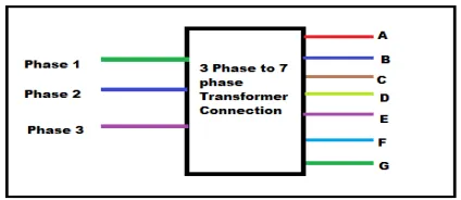
Figure 1: Block representation of the proposed system
We know that from the theory multi-phase motors are invariably supplied by ac/dc/ac converters. Thus, the multiphase electric drive is limited for the modelling and control of the supply systems [13]. Our main work is to develop static transformation system to change the phase number from three to eleven-phase (where n>3 and odd). Now we, are generating a novel phase transformation system which convert three phase to an eleven-phase supply [14].
In Multiphase, system six phase and twelve phase is found to produce less ripple with a high frequency in an AC-DC rectifier system. Thus six and twelve phase transformers are designed to feed a number of pulses rectifier system and technology has matured [15]. Recently, twenty four phase and thirty six phase transformer systems have proposed for supplying a number of pulse rectifier systems [12-16]. These designs are also available for an odd number of phases, such as five, nine and eleven etc.
In this paper we have proposed a special transformer connection scheme to get a balance eleven-phase output supply from the balance three-phase input supply. The expected application areas of the power transformer are the electric power transmission system and power electronic converters (AC-DC and AC-AC), and the multiphase electric drive system. The block represented of the proposed system is shown in figure 1.The fixed voltage and fixed frequency available grid supply can be transformed to the fixed frequency Seven-phase output supply. The output however, may be made variable by inserting the autotransformer at the primary side. The input and output supply can be arranged in the following manner [20] as below.
I) Input Star, Output Star. II) Input Star, Output heptagon. III) Input Delta, Output Star. IV) Input Delta, Output heptagon.
The input has being three-phase system the windings are connected in a usually fashion. The hendecagon output connection may be derived following a similar approach. The output/secondary side connection is discussed in the following subsections.
II.WINDING ARRANGEMENT OF SEVEN PHASE STAR OUTPUT
Here separates iron core are designated with one primary and three secondary coils, six terminal of primary side are connected in an adoptable manner resulting in star and or delta connection and the 18 terminals of secondary’s are connected in a different fashion in a star/hendecagon output. The new connection scheme of secondary winding to obtain an input star and output star is illustrated in figure 2 and the corresponding phasor diagram is shown in figure 4 similarly for input delta and output star connection is also shown in the figure 3. The construction of the output (star) phase with requisite phase angles of 360/7=51.42° between each phase is obtained using appropriate turn ratio and the governing phasor equation is given in (3). Selecting the turn ratio is the key in creating the phase displacement in the output phases.
ISSN (Print) : 2320 – 3765 ISSN (Online): 2278 – 8875
I
nternational
J
ournal of
A
dvanced
R
esearch in
E
lectrical,
E
lectronics and
I
nstrumentation
E
ngineering
(A High Impact Factor, Monthly, Peer Reviewed Journal)
Website: www.ijareeie.com
Vol. 7, Issue 6, June 2018
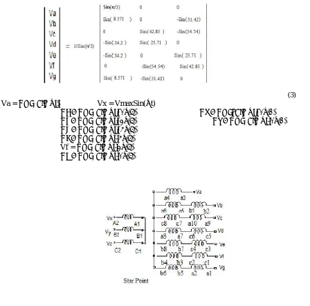
Vx [cos (2 /7) + j sin (2 /7)] – Vz [cos (1.66 /7)-j sin (1.66 /7)] = 1 (1) Equating real and imaginary parts and solving Vx and Vz We get,
│Vx│= sin (1.66 /7)/ sin ( /3) =0.5271
│Vz│=-sin(2 /7)/sin( /3)=0.6243 (2)
Thus equation (3) is the result voltage of the two different coils; one output phase is generated from only one coil namely “a3a4” in contrast to another phase utilizes by two coils.
(3) Va = VmaxSin(ωt) Vx = VmaxSin(ωt)
Vb = VmaxSin(ωt+2π/7) Vy = VmanSin(ωt+2π/3)
Vc = VmaxSin(ωt+4π/7) Vz = VmaxSin(ωt-2π/3)
Vd = VmaxSin(ωt+6π/7)
Ve = VmaxSin(ωt-6π/7)
Vf = VmaxSin(ωt-4π/7)
Vg = VmaxSin(ωt-2π/7)
(*MWT=Multi-winding transformer)
Figure 3:A schematic drawing of a three phase power system utilizing a three phase to seven phase “star-star” power transformer with secondary windings.
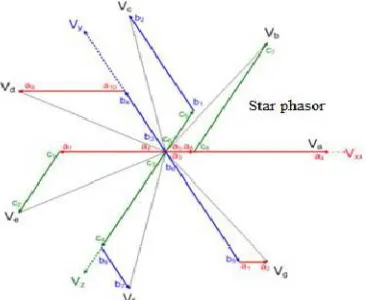
Figure 4: Phasor diagram of the proposed transformer conection (star-star)
III. WINDING ARRANGEMENT OF SEVEN PHASE DELTA OUTPUT
ISSN (Print) : 2320 – 3765 ISSN (Online): 2278 – 8875
I
nternational
J
ournal of
A
dvanced
R
esearch in
E
lectrical,
E
lectronics and
I
nstrumentation
E
ngineering
(A High Impact Factor, Monthly, Peer Reviewed Journal)
Website: www.ijareeie.com
Vol. 7, Issue 6, June 2018
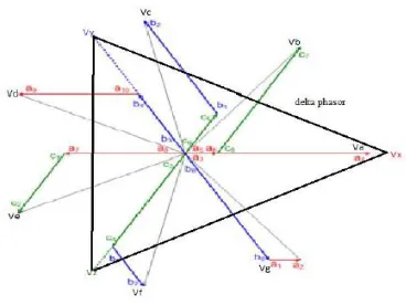
Figure 5: Proposed transformer winding delta-star connection
(*MWT = Multi-winding transformer)
Figure 6: A schematic drawingof a three phase power system utilizing a three phase to seven phase “delta-star” power transformer with secondary windings.
IV.SIMULATION
The new designed/structure is at the first using “Sim power system” block set of the MATLAB/Simulink sofware. Multiwinding transformer block is chosen from the sim-power system block library and the turn ratios are set in the dialog box and the simulation is run. The resulting input and output current and votage waveform. The output will be unbalance if input is unbalanced and also if the input is balance then output is also balance. The three phase output from a seven phase input supply can also be obtain in similar fasion.
Figure 9: MATLAB/SIMULINK model of Three-to-Seven phase Star Transformation
Fig 10: Input current and voltage waveforms of Star-Star
ISSN (Print) : 2320 – 3765 ISSN (Online): 2278 – 8875
I
nternational
J
ournal of
A
dvanced
R
esearch in
E
lectrical,
E
lectronics and
I
nstrumentation
E
ngineering
(A High Impact Factor, Monthly, Peer Reviewed Journal)
Website: www.ijareeie.com
Vol. 7, Issue 6, June 2018
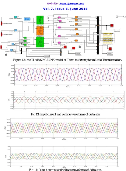
Figure 12: MATLAB/SIMULINK model of Three-to-Seven phases Delta Transformation.
Fig 13: Input current and voltage waveforms of delta-star
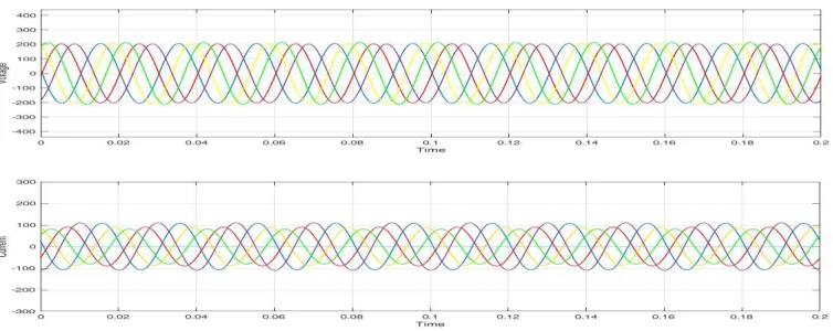
Fig 14: Output current and voltage waveforms of delta-star.
V. RESULT AND DISCUSSION
In this simulation we have No-load and load tests are performed on the three to Seven phase transformers and their load test are performed by connecting seven phase RL load. The value of load is given by R=50Ω and L=5mH. Thus the
voltage is also balance. Any unbalancing in the input is directly reflected in the output phases. Under no-load conditions, 440 V is applied at the primary side. The input side voltage and current wave forms, under no-load and loaded steady-state conditions, the input voltage and currents under loaded conditions are 440 V and 24 A are recorded and shown in Figure 10. Corresponding no-load and loaded condition voltage and current wave forms for the secondary side (seven phase) and the loaded current in the secondary side is nearly 14 A and the voltage is 400 V are presented in the Figure 14.
VI.CONCLUSION
The new connection scheme and the phasor diagram along with the turn ratios are illustrated. This method required the main data of transformer, the phase shifting and as well as the winding connections of the transformer. The seven-phase induction motor under a loaded condition is used to prove the viability of the transformation system. The 3/7 AC multiphase transformer has been simulated by using MATLAB simulation software, which has been proved to be powerful tools to simulates such a typical connection transformers.
REFERENCES
[1] Satish Karekar (2016). A Possibilities of Simulation of Three Phases to Thirteen Phase’s Transformer Connection. IJRASET International Journal for Research in Applied Science & Engineering Technology. Volume 4 Issue IV, April 2016.
[2] Satish Karekar (2016).Modelling and Simulation of Three phases to Seven phases Transformer Connecttion. IJRASET International Journal for Research in Applied Science & Engineering Technology. Volume 4 Issue IV, April 2016.
[3] Hoteit Ahmad and Hamidovich Gaitov (2012). AC/DC Power Conversion System Using 3/9 Multiphase Transformer.IJCSI International Journal of Computer Science Issues, Vol. 9, Issue 4, No 1, pp no. 68-70.
[4] Furmanczyk, F . and Stefanich, M.(2004). Demonstration of very high power airborne AC to DC converter. Power systems conference, Reno, Pp. No.2002- 01- 3210.
[5] Basic, D. , Zhu, J.G. and Boardman, G.(2003). Transient performance study of brushless doubly fed twin stator generator. IEEE Trans. Power Convers, vol. 18, no.3, pp. 400-408.
[6] Stewart, J.R., Kallaur, E. and Grant, J.(1984). Economics of EHV high/Phase order Transmission .IEEE Tras. Power App. System, vol .PAS- 103, no. 11, pp. 3386-3392.
[7] Singh, G. K. (2008). Modelling and experimental analysis of a self excited six-phase induction generator for standalone renewable energy generation. Renewable. Energy, vol. 33, no. 7, pp. 1605-1612.
[8] Landes, T. L., Richeda, R. J., Kriszanskas, E., Stewart, J.R. and Brown, R. A.(1998) High phase order economic: Constructing a new transmission line. IEEE Trans. Power Del, vol. 13, no. 4, pp. 1521-1526.
[9] Abbas, M. A., Chirsten, R. and jahns, T. M. (1984). Six- phase voltage source inverter driven induction motor.IEEE Trans. Ind. Appl., vol. IA-20,no. 5, pp. 1251-1259.
[10] Jones, M. and Levi, E. (2002). A literature survey of the state-of –the-art in multiphase drives. In proc. Int. UPEC, Stafford, U.K. pp. 505-510. [11] Choi, S., Lee, B. S. and Enjeti,P. N.(1997). New 24-pulse diode rectifier systems for utility interface of high power AC motor drives.IEEE
Trans. Ind. Appl., vol. 33, no. 2, pp no.531-541.
[12] Srinivas goud, L. and Srivani, T. (2013). A Simulation of three phase to multiphase transformation using a special transformer. International Journal of Science and Research (IJSR). Volume 2 Issue7, pp no. 351-357.
[13] Iqbal, A. (2005). Modelling and control of series-connection Five-phase and six phase two-motor drives. Ph.d. dissertation, school Eng., Liverpool John Moores Univ., school eng., Liverpool, U.K.
[14] Tewari, S. N., Singh, G.K. and Saroor, A.B.(1992). Multiphase power transmission research-A survey,”Electr. Power System. Res., vol. 24, pp. 207-215.
[15] Singh, B. and Gairola,S.(2008). A 24 pulse AC-DC converter emplying a pulse doubling technique for vector controlled industries motor drives. IETE J.Res.,vol. 54, no. 4, pp. 314-322.
[16] Iqbal, A., Moinuddin, S., Khan, M.R., Ahmed, SK. M. and Abu-Rub, H.(2012). A novel three-phase to seven-phase transformation using special transformer connection. IEEE Trans. EnergyConversion, Vol. 27, no. 3.
[17] Iqbal, A. (2005).Modelling and control of series-connection Five-phase and six phase two-motor drives.Ph.d. dissertation, school Eng., Liverpool John Moores Univ., school eng., Liverpool, U.K.
[18] Levi, E. (2008).Multiphase electric machine for the varable- speed application,” IEEE Trans Ind, Electron. vol, 55, no. 5, pp. 1893-909. [19] Somashekar, B., Chandrasekhar B., and D Livingston. David (2013).Modelling and Simulation of three to nine phase using special transformer
connection.IJETAE vol. 3. pp. no. 630-638.
ISSN (Print) : 2320 – 3765 ISSN (Online): 2278 – 8875
I
nternational
J
ournal of
A
dvanced
R
esearch in
E
lectrical,
E
lectronics and
I
nstrumentation
E
ngineering
(A High Impact Factor, Monthly, Peer Reviewed Journal)
Website: www.ijareeie.com
Vol. 7, Issue 6, June 2018
[21] Bojoi , R., Farina, F., Profumo F. and Tenconi, A. (2006). Dual-Three phase induction machinedrives control- A survey. Inst. Elect. Eng. Jpn. Trans. Ind.Appl., vol. 126, no. 4, pp. 420-429.
[22] Ward, E.E. and Harer, H. (1969). Preliminary investigation of an inverter –fed 5 phase induction motor.proc. Inst. Elect. Eng., vol.1166, no. 6. [23] Portela, C. M. and Tavares, M.C. (1993). Six-phase transmission line-propagation characteristics and new three-phase representation.IEEE
Trans. Power Del., vol. 18, no. 3, pp. 1470-1483.
[24] Arahal, M.R and Duran, M.J (2009). Pi tuning of five-phase drives with third harmonic injection.Control Eng. Practical, vol. 17, pp. 787-797. [25] Duran, M.J., Salas, F. and Arahal, M.R. (2008). Bifurcation analysis of five-phase induction motor drives with third harmonic injection. IEEE
Trans. Ind. Electron. Vol. 55, no. 5, pp. 2006-2014.
[26] Ojo, O. and Dong, G. (2005). Generalized discontinuous carrier-based PWD modulation scheme for multi-phase converter-machine system.Presnted at the IEEE Ind. Appl. Soc. Annu. Meet. IAS (CD-ROM Pp no. 38P3),Hong Kong, China.
[27] Ojo, O. and Davidson, I.E. (2000) .PWM-VSI inverter- assisted stand-alone dual stator winding induction generator. IEEE Trans Ind. Appl., vol. 36, no. 6, pp. 1604-1611.
[28] K. R. Chowdhury, M. Di Felice, “Search: a routing protocol for mobile cognitive radio ad hoc networks,” Computer Communication Journal, vol. 32, no. 18, pp. 1983-1997, Dec.20
[29] K. M. Passino, “Biomimicry of bacterial foraging for distributed optimization,” IEEE Control Systems Magazine, vol. 22, no. 3, pp. 52-67, 2002.
[30] Q. Wang, H. Zheng, “Route and spectrum selection in dynamic spectrum networks,” in Proc. IEEE CCNC 2006, pp. 625-629, Feb. 2006. [31] R. Chen et al., “Toward Secure Distributed Spectrum Sensing in Cognitive Radio Networks,” IEEE Commun. Mag., vol. 46,pp. 50–55, Apr.
2008.
[32] H. Khalife, N. Malouch, S. Fdida, “Multihop cognitive radio networks: to route or not to route,” IEEE Network, vol. 23, no. 4, pp. 20-25, 2009.
[33] Y.-C. Liang et al., “Sensing-Throughput Trade-off for Cognitive Radio Networks, ”IEEE Trans. Wireless Commun., vol. 7, pp. 1326–37 ,April 2008.
[34] P. K. Visscher, “How Self-Organization Evolves,” Nature, vol. 421, pp. 799–800 Feb.2003.
[35] K. M. Passino, “Biomimicry of bacterial foraging for distributed optimization,” IEEE Control Systems Magazine, vol. 22, no. 3, pp. 52-67, 2002.
[36] Q. Wang, H. Zheng, “Route and spectrum selection in dynamic spectrum networks,” in Proc. IEEE CCNC 2006, pp. 625-629, Feb. 2006. [37] R. Chen et al., “Toward Secure Distributed Spectrum Sensing in Cognitive Radio Networks,” IEEE Commun. Mag., vol. 46, pp. 50–55, Apr.
2008.
[38] H. Khalife, N. Malouch, S. Fdida, “Multihop cognitive radio networks: to route or not to route,” IEEE Network, vol. 23, no. 4, pp. 20-25, 2009.
[39] Y.-C. Liang et al., “Sensing-Throughput Trade-off for Cognitive Radio Networks, ”IEEE Trans. Wireless Commun., vol. 7, pp. 1326–37 ,April 2008.