Issue 2, September 1998
TEMS, INC. as a guide for system installers and users. It provides information necessary to properly install, program, operate, and maintain the system.
The contents of this guide, which reflect current INTER-TEL standards and which docu-ment software version 827.8010, are subject to revision or change without notice. Soft-ware packages released after the publication of this guide will be documented in addenda to the guide or succeeding issues of the guide.
If additional information is required, please contact your dealer or service representative.
Inter-Telis a registered trademark of Inter-Tel, Incorporated.
Inter-Tel Integrated SystemsTMis a trademark of Inter-Tel Integrated Systems, Inc.
Inter-Tel Inside TrackTMis a trademark of Inter-Tel Integrated Systems, Inc.
7DEOH 2I &RQWHQWV
7DEOH 2I &RQWHQWV
Y
/LPLWHG :DUUDQW\
YLLL
0LFURVRIW :LQGRZV /LFHQVH
L[
:HOFRPH 7R ,QVLGH 7UDFN
,QWURGXFWLRQ 2YHUYLHZ $ERXW 7KLV 8VHU *XLGH ,QVLGH 7UDFN $QG <RXU 7HOHSKRQH 6\VWHP $YDLODEOH 5HSRUW 7\SHV
(TXLSPHQW 5HTXLUHPHQWV
',3 6ZLWFKHV $;;(6625< 7DON 3& DQG $[[HQW 7DON &RPPXQLFDWLRQV 3DUDPHWHUV ,QWHU7HO 1HW6ROXWLRQV 56 &RQQHFWRUV *XLGHOLQHV IRU 0DNLQJ DQ 56 &RQQHFWLRQ 'DWD 3LQV UHTXLUHG *URXQG 3LQV UHTXLUHG &RQWURO DQG 6WDWXV 3LQV UHTXLUHPHQWV YDU\ DPRQJ PDQXIDFWXUHUV 7HOHSKRQH 6\VWHP 56 &RQQHFWRU 3LQ 2XW $;;(66 56 0RGXODU -DFN 3LQ 2XW $[[HQW '%) &RQQHFWRU 3LQ 2XW 3&'30 '%) &RQQHFWRU 3LQ 2XW '%) 3LQ 2XW 3& '%0'%0 &RQQHFWRU 3LQ 2XW '%0 3LQ 2XW '%0 3LQ 2XW %XIIHU %R[ '% &RQQHFWRU 3LQ 2XW '% 3LQ 2XW WR 3& '% 3LQ 2XW WR 3%; 02'(0 '%) &RQQHFWRU 3LQ 2XW '%) 3LQ 2XW
+DUGZDUH ,QVWDOODWLRQ
%XIIHU %R[ ,QVWDOOLQJ WKH 6RIWZDUH .H\ ,QVWDOOLQJ WKH 3ROO&DW %XIIHU %R[ ,QVWDOOLQJ WKH 2SWLRQDO 7DQGHP 8QLW ,QVWDOOLQJ WKH &5% 8QLW ,QVWDOOLQJ WKH ,/% 8QLW &OHDULQJ DQG 7HVWLQJ WKH 0HPRU\ )RU 3ROO&DW 7DQGHP DQG &5% XQLW )RU ,/% 8QLW ,QVWDOOLQJ $GGLWLRQDO 0HPRU\ ,QVWDOOLQJ WKH 2SWLRQDO 0RGHP $;;(6625< 7DON 3& DQG $[[HQW 7DON 0DNLQJ <RXU 2ZQ &XVWRP &DEOH 8VLQJ $;;(66$[[HQW 8QLYHUVDO 56 .LW
6RIWZDUH ,QVWDOODWLRQ
8VLQJ ,QVLGH 7UDFN
*XLGHOLQHV )RU 3UHSDULQJ DQG 3ULQWLQJ 5HSRUWV 7R 3URJUDP 5HSRUWV 7R *HQHUDWH $QG 3ULQW 5HSRUWV 7RROEDU $QG 3XOO'RZQ 0HQXV /RFDWLRQ 3XOO'RZQ 0HQX 6\VWHP 3XOO'RZQ 0HQX :LQGRZV 3XOO'RZQ 0HQX +HOS 3XOO'RZQ 0HQX /RFDWLRQ 3URJUDPPLQJ :LQGRZ 3URJUDPPLQJ 60'$ 5HSRUWV 7R 3URJUDP $ 5HSRUW 6DPSOH 5HSRUW )RUPDWV 7R 6HOHFW 60'5 'DWDEDVHV 7R 6RUW 5HSRUW ,QIRUPDWLRQ 7R 6HOHFW 5HSRUW &ULWHULD 5DQJHV &DOO 7\SHV 7R &RS\ 5HSRUWV 7R 3ULQW 5HSRUWV 3ULQW &RPPDQG 3ULQWHU 6HWXS 7R 3UHYLHZ 5HSRUWV 3URJUDPPLQJ 60'5 $QG (QKDQFHG 'DWDEDVHV 7R 3URJUDP &UHDWH 2U 'HOHWH 60'5 'DWDEDVHV 3URJUDPPLQJ $Q ([LVWLQJ 2U 1HZ 'DWDEDVH *HWWLQJ $Q $FFXUDWH 'DWH 5HFRUGLQJ 'RZQORDGLQJ &DOO 5HFRUGV )URP $ %XIIHU 56 &RQQHFWLRQ
'HOHWLQJ 5DZ )LOHV
5HSODFHPHQW 3DUWV
2UGHULQJ 3DUWV
Limited Warranty
Inter-Tel Integrated Systems, Inc. warrants the physical diskette(s) and physical docu-mentation enclosed herein (but not any diskettes or docudocu-mentation distributed by you) to be free of defects in materials and workmanship for a period of sixty days from the pur-chase date. If Inter-Tel Integrated Systems receives notification within the warranty peri-od of defects in materials or workmanship, and such notification is determined by Inter-Tel Integrated Systems to be correct, Inter-Inter-Tel Integrated Systems will replace the defective diskette(s) or documentation. DO NOT RETURN ANY PRODUCT UNTIL YOU
HAVE CONTACTED YOUR DEALER. YOUR DEALER WILL BE RESPONSIBLE FOR OBTAINING RETURN AUTHORIZATION.
The entire and exclusive liability and remedy for breach of this Limited Warranty shall be limited to replacement of defective diskette(s) or documentation and shall not include or extend to any claim for or right to recover any other damages, including but not limited to, loss of profit, data, or use of the software, or special, incidental, or consequential damages or other similar claims, even if Inter-Tel Integrated Systems has been specifically advised of the possibility of such damages. In no event will Inter-Tel Integrated System’s liability for any damages to you or any other person ever exceed the lower of suggested list price or actual price paid for the license to use the software, regardless of any form of the claim.
THIS WARRANTY IS IN LIEU OF AND EXCLUDES ALL OTHER WARRANTIES, EX-PRESS OR IMPLIED, INCLUDING, BUT NOT LIMITED TO, ANY IMPLIED WAR-RANTY OF MERCHANTABILITY OR FITNESS FOR A PARTICULAR PURPOSE. THERE ARE NO WARRANTIES WHICH EXTEND BEYOND THIS LIMITED WAR-RANTY. Specifically, Inter-Tel Integrated Systems makes no representation or warranty
that software is fit for any particular purpose and any implied warranty of merchantability is limited to the sixty-day duration of the Limited Warranty covering the physical dis-kette(s) and documentation only (and not the software) and is otherwise expressly and specifically disclaimed.
This Limited Warranty does not apply to any products damaged by improper handling, normal wear and tear, accidents, lightning damage, negligence, or improper use or main-tenance and does not apply to products altered without authorization by Inter-Tel Inte-grated Systems.
Microsoft Windows License
Note: The following information is provided by Microsoft Corporation, regarding their licensing policies.
The Inside Track software operates in a graphics environment called Microsoft Windows, created by Microsoft Corporation. An extension of the MS-DOS operating system,
Micro-soft Windows gives a standard look and feel to the Inside Track Micro-software and all other Windows applications.
The Inside Track package contains all the software necessary to generate reports. You must run the Inside Track software under Microsoft Windows version 3.1 or higher.
With Microsoft Windows, you can take advantage of these additional features of the
Windows environment:
• Running multiple applications:You can run several applications under Windows at one time and easily switch between them, creating an integrated work environment.
• Data exchange between applications:You can transfer data between the Inside Track software and other standard DOS applications as well as other Windows applica-tions.
• Windows control of the DOS environment: From the Windows environment you have easy access to all Windows and non-Windows applications, files, directories, and disks, and control all DOS-related tasks such as directory or file management and formatting disks.
To run the Inside Track software with other applications under Microsoft Windows, you need to license and install Microsoft Windows version 3.1 or higher.
Welcome To Inside Track
Introduction
Thank you for purchasing Inter-Tel’s Inside Track software package. This exciting new product allows you to create customized call management and accounting reports from your telephone system’s call record data. You can use these reports to manage your call-ing costs, analyze system traffic, and track employee productivity.
The software, which is loaded on your personal computer (PC) and operates under Micro-soft Windows, uses the call records from your telephone system to sort and create the desired reports. These call records are generated by the Station Message Detail Recording (SMDR) feature on your telephone system.
The SMDR call records are stored in a buffer box connected to your telephone system. Or, if you have an Inter-Tel AXXESS or Axxent telephone system, the SMDR call records can be stored on the optional AXXESSORY Talk PC or Axxent Talk hard disk instead. Inter-Tel NetSolutions customers can also get call record data from the NetSolutions office.
The SMDR call records (whether they are stored in a buffer box, on an AXXESSORY Talk PC, or with Inter-Tel NetSolutions) are then transferred to your PC where you can use the Inside Track software to sort the data and generate various reports.
Overview
As shown in the diagram below, the Inside Track software can contain information for several “locations,” which are each made up of several reports. Each report is then made up of one or more SMDR databases (and can include an enhanced database) that contain call records.
Inside Track Software
Location
Location
Location
Report
Report
Report
Report
Enhanced
Database
SMDR
Database
About This User Guide
This user guide provides all of the information you will need to install and use Inside Track. It includes information on the following:
• Inside Track And Your Telephone System
• Available Report Types
• Equipment Requirements
• Call Record Storage Sources
— Buffer Box
— AXXESSORY Talk PC
— Inter-Tel NetSolutions
• Hardware Installation
• Software Installation
• Using Inside Track
Inside Track And Your Telephone System
The Inside Track software can be used with the SMDR call records from the following Inter-Tel Integrated Systems, Inc. and Premier Telecom Products, Inc. telephone systems:
Inter-Tel Telephone Systems
• IMX 1224/2460• IMX 2448
• IMX 256
• IMX 416/832
• GMX-48
• GX-120
• GMX-152D
• GMX 256
• GMX 416/832
• Inter-Tel Axxent
• AXXESS
Note: The new version 2.0 Inside Track software (part number 827.8854) is not com-patible with the earliest releases of AXXESS 5.0 software (versions: 5.000, 5.010, 5.020, and 5.030). In order to use this software on an AXXESS system, you must upgrade your
AXXESS software to version 5.040 or higher.
Premier Telephone Systems
• ESP
• ESPMDX
• ESPDX
Available Report Types
The reports can be customized to add as much detail as you like. For example, the descrip-tion, tenant group, and department information for each extension number can be included in the reports. This “enhanced” information allows you to generate a complete profile of your telephone system’s users. And, if desired, two or more sets of SMDR call records can be combined to generate a single summary report. Reports can be generated to include any combination of the following information:
• Account Code
• Account Code Description
• Call Cost
• Call Elapsed Time
• Call Start Time
• Call Type
• Date
• Location Of Telephone Number Called
• Station Description
• Station Extension
• Station Username
• Telephone Number
• Tenant/Department
• Trunk Description
Call records can be arranged using the report templates with up to three “sort keys” (sta-tions, trunks, etc.) that determine what information is presented. The report templates are as follows:
• Detailed by Time (default): This lists the call records in the report by the time of the
call. It details calls by date and time, breaking the calls into sections using the first sort key.
• Detailed by Time with Subheaders: This is the same as the Detailed by Time report,
except that report has subsections using the second sort key.
• Summary: This report type gives summary totals for calls in each section. Sections are
determined by the first sort key.
• Summary with Subheaders: This is the same as Summary report, except that totals are
given for subsections. The subsections are determined by the second sort key.
• Summary by Number: This lists the call records by number of calls placed to specific
telephone numbers. The totals are listed in sections determined by the first sort key.
• Station by Number with Subheaders: This is the same as Station by Number report,
except that report sections are divided by the first sort key and then subdivided by the second sort key.
• Summary Totals: This combines data to present total call cost, duration, and number of
calls for the selected sort key (such as account codes).
• Totals Summary: This report type gives a list of the total number of calls made by each
extension, the duration of those calls, and an approximate call cost, in other words this report give you a condensed version of the “Summary” report.
Equipment Requirements
Personal Computer (PC)
To use the Inside Track software, your PC must have the following minimum require-ments:
• IBM-compatible
• 80386 or higher microprocessor
• Microsoft Windows 3.1, Windows 95, or Windows NT 4.0 (It does not run under Win-dows NT 3.51, because 3.51 is not compatible with the software security key.)
• 2 megabytes (MB) RAM (4MB recommended)
• 45MB available hard disk space (5MB for the software and 40MB recommended for data manipulation)
Note: The exact amount of hard disk space needed for data manipulation depends on the size of the files being sorted.
• 3½-inch (1.44MB) double-sided/high-density floppy disk drive (5¼-inch disks are also available)
• If connecting directly to the buffer box, an available COM port (RS-232 serial
commu-nications port)
• If connecting to the buffer box via modem, an internal or external modem • Parallel port
• Optional printer
Call Record Storage Sources
Your telephone system’s SMDR call records can be stored using any of the following methods:
• The SMDR call records can be stored in a buffer box connected to your telephone system.
• If you have an Inter-Tel AXXESS or Axxent telephone system, the SMDR call records can be stored on the optional AXXESSORY Talk PC or on the Axxent Talk hard disk.
• Inter-Tel NetSolutions customers can receive call record data on a floppy disk from the NetSolutions billing system.
Buffer Box
PollCat Buffer Box Specifications
The PollCat buffer box is a solid-state storage system designed for call record data collec-tion. It uses a double-data compression method to store more than double the amount of characters that could normally be stored in its RAM (random access memory). A replace-able lithium battery protects memory for up to sixty days in the event of a power failure. The PollCat buffer box attaches to the telephone system using an RS-232 port. Refer to page 34 for instructions on connecting the PollCat buffer box to your telephone system.
To ensure that the buffer box is connected properly to your telephone system, you may want your local telephone dealer to perform the installation.
Physical Dimensions
The PollCat buffer box has the following dimensions:
Height Width Depth Weight
2.0 in. (5.0 cm.) 10.5 in. (26.25 cm.) 7.0 in. (17.5 cm.) 3.0 lbs. (1.35 kg.)
RS-232 Connectors
The PollCat buffer box has two RS-232 connectors. The connector labeled PBX is con-nected to your telephone system. The connector labeled COMPUTER is concon-nected to your PC or to an external modem. Refer to RS-232 Connectors section, page 20, for de-tailed RS-232 information.
Pause Button
The PAUSE button on the front of the PollCat buffer box allows you to halt the data being transferred to your PC. Data coming from the telephone system to the PollCat buffer box cannot be halted unless the RS-232 cable is removed or unless the memory in the PollCat buffer box is full.
When the PAUSE button is pressed to halt data, the LED under the button is lit. When the button is pressed again, the data transmission resumes and the LED is unlit.
If necessary, the memory in the PollCat buffer box can be cleared and tested by pressing the PAUSE button while turning on the AC power switch (see page 42 for instructions).
Fuse
There is a 125mA, 250VAC, slow-acting fuse on the back of the PollCat buffer box to protect it against shock hazards.
DIP Switches
The DIP switches on the back of the PollCat buffer box are used to select the bit rate (bps), parity type, and X-ON/X-OFF option.
There are two independent bit rate settings on the PollCat buffer box, one for the connec-tion to the telephone system and one for the connecconnec-tion to your PC (or an external mo-dem). The PollCat buffer box can communicate with the telephone system at 300, 1200, 2400, or 9600 bps. It can communicate with your PC at 300, 600, 1200, 2400, 4800, or 9600 bps. Parity can be odd or even; however, X-ON/X-OFF should be disabled.
Light-Emitting Diodes (LEDs)
There are five light-emitting diodes (LEDs) on the front of the PollCat buffer box. The LEDs are used to indicate the following information:
• Power On:This LED lights when the unit is receiving AC power. The power cord and power switch are located on the back of the unit.
• % Full:The flash rate of this LED indicates approximately how full the memory is. When the memory is empty, the LED is unlit. When the memory is between 0% and 10% full, the LED flashes once before pausing. When the memory exceeds 10%, the LED flashes twice up to 20% full, three times up to 30% full, and so on. For example, if the memory is 43% full, the LED flashes five times, then pauses for a second before flashing five times again. If the memory is full (100%), the LED is solidly lit.
On GMX-48, GX-120, GMX-152D, IMX 2448, IMX 1224/2460, and ESP telephone systems, this LED may flash once even though the memory is actually empty.
• 80% Full:When memory is 80% full, this LED is lit to indicate that the memory is almost full and that a download should be performed.
• Send Data:This LED flashes whenever information is being transferred from the PollCat buffer box to your PC.
Optional Memory Expansion Chips
The PollCat buffer box comes equipped with 64k RAM (two 32k chips), which is enough memory to store approximately 1000–1200 call records. An additional 64k (two chips) of memory can be installed for a total of 128k of memory (for 2000–2400 call records). Or, an additional 128k (six chips) of memory can be installed for a total of 256k of memory (for 4000-4500 call records).
Optional Tandem Unit
For even greater storage capacity, a specially-designed “Tandem” unit can be connected in series with the PollCat buffer box. The Tandem unit, which is almost identical in design and function to the PollCat buffer box, is installed between the telephone system and the PollCat buffer box. When the PollCat buffer box is almost full, subsequent call record data is automatically stored in the Tandem unit. Refer page 36 for instructions on installing the Tandem unit.
The RS-232 connectors, LEDs, PAUSE button, battery, and fuse on the Tandem unit are the same as those on the PollCat buffer box. And, like the PollCat buffer box, the Tandem unit can be equipped with memory expansion chips, for a combined maximum of 512k memory.
Although the PollCat buffer box and the Tandem unit are similar, they are not inter-changeable.
Optional Modem Connection
Your PC does not have to be connected directly to the PollCat buffer box. Call records can be transferred via modem from the PollCat buffer box to your PC. This is especially useful if you are processing call records for several telephone systems. To download call records from a remote PollCat buffer box to your PC, an external auto-answer modem must be connected to the PollCat buffer box’s PC (COMPUTER) port.
CRB Unit Specifications
The Call Record Buffer (CRB) unit provides up to 256k of non-volatile, battery-backed memory (CMOS static RAM). It can reliably store data for up to 60 days, even when powered off. The unit is powered by an AC adapter (9VDC @ 500mA).
Physical Dimensions
The CRB unit, which is considerably smaller than the original PollCat unit has the follow-ing dimensions:
Height Width Depth Weight
1.2 in. (3.0 cm.) 4.5 in. (11.4 cm.) 6.0 in. (15.2 cm.) 1.0 lbs. (0.5 kg.)
RS-232 Connectors
The CRB unit has two RS-232 connectors. The connector labeled PBX is connected to your telephone system. The connector labeled COMPUTER is connected to your PC or to an external modem. Ensure that the RS-232 cables have the correct pinouts as outlined in the diagram below. Refer to RS-232 Connectors section, page 20, for detailed RS-232 information.
“Almost Full” Audible Alarm
The CRB unit can be set up to emit a beeping tone when its memory is 80% full. The tone’s intensity increases as more memory is used.
Light-Emitting Diode (LED) Indicators
There are four light-emitting diode (LED) indicators on the top of the CRB unit as shown in the diagram on the next page. The LEDs are used to indicate the following information:
• ON:This LED lights when the unit is receiving AC power. The power connector and power switch are located on the PBX end of the unit.
• MEM:The flash rate of this LED indicates approximately how much memory is cur-rently being used. When the memory is empty, the LED is unlit. When the memory is between 0% and 10% full, the LED flashes once before pausing. When the memory exceeds 10%, the LED flashes twice up to 20% full, three times up to 30% full, and so on. For example, if the memory is 43% full, the LED flashes five times, then pauses for a second before flashing five times again. If the memory is full (100%), the LED is solidly lit.
On GMX-48, GX-120, GMX-152D, IMX 2448, IMX 1224/2460, and ESP telephone systems, this LED may flash once even though the memory is actually empty.
• PBX:This LED flashes whenever the unit is receiving information from your tele-phone system (even if the buffer box is turned off). This allows you to verify that the unit is properly connected to the telephone system and that call records are being trans-ferred. If this LED is continually lit, it may indicate a cable or telephone system port problem.
• PAUSE:This LED lights whenever the data transfer process has been temporarily suspended for some reason, such as: the unit receives an X-OFF command, the unit receives a low DTR signal, X-ON/X-OFF handshaking is disabled, or the PAUSE but-ton on the top of the unit is pressed.
DIP Switches
The DIP switches on the bottom of the CRB unit are used to select the bit rate, audible alarm option, data compression scheme (including parity type and bit rate), X-ON/X-OFF option, and X-ON single call record mode. Refer to the manufacture’s manual for detailed information.
Figure 2 Front and Rear Views of the CRB-256K Unit
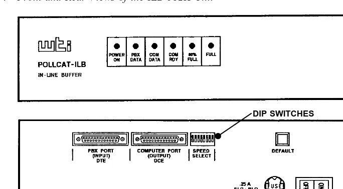
ILB Unit Specifications
The In-Line Buffer (ILB) unit provides up to 512k of non-volatile, battery-backed memory (CMOS static RAM). It can reliably store data for up to 60 days, even when powered off. The unit is powered by a 115VAC power source.
Physical Dimensions
The ILB unit, which is larger than the original PollCat unit, has the following dimensions: Height
Width Depth Weight
4.0 in. (10.2 cm.) 17.0 in. (43.2 cm.) 8.5 in. (21.6 cm.) 6.1 lbs. (2.8 kg.)
RS-232 Connectors
The ILB unit has two RS-232 connectors. The connector labeled PBX PORT DTE is nected to your telephone system. The connector labeled COMPUTER PORT DCE is con-nected to your PC or to an external modem. Ensure that the RS-232 cables have the correct pinouts as outlined in the diagram below. Refer to RS-232 Connectors section, page 20, for detailed RS-232 information.
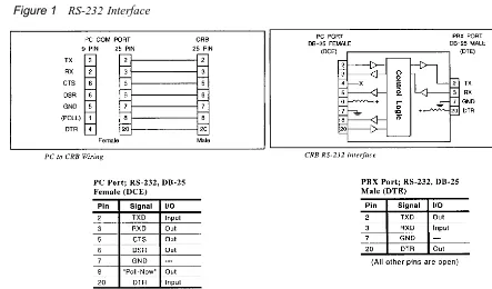
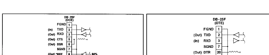
Figure 3 RS-232 Interface
FGND
F
Light-Emitting Diode (LED) Indicators
There are six light-emitting diode (LED) indicators on the front of the ILB unit as shown in the diagram on the next page. The LEDs are used to indicate the following information:
• POWER ON:This LED lights when the unit is receiving AC power. The power cable and power switch are located on the right on the back of the unit.
• PBX DATA:This LED flashes whenever the unit is receiving information from your telephone system (even if the buffer box is turned off). This allows you to verify that the unit is properly connected to the telephone system and that call records are being transferred. If this LED does not flash, it may indicate a cable or telephone system port problem.
• COM DATA:This LED flashes when data is released from the Computer Port.
• COM RDY:This LED flashes when the DTR signal is present at the Computer Port which is ready to release data.
• 80% FULL:This LED lights when the internal memory is approximately 80% full.
• FULL:This LED lights when the internal memory is 100% full.
DIP Switches
The DIP switches on the back of the ILB unit are used to select the bit rate, data compres-sion scheme (including parity type and bit rate), single-line release function (enable/dis-able), and optional external modem mode. Refer to the manufacture’s manual for detailed information.
Figure 4 Front and Rear Views of the ILB-512K Unit
AXXESSORY Talk PC and Axxent Talk
If you have an Inter-Tel AXXESS or Axxent telephone system equipped with an optional AXXESSORY Talk PC an Axxent Talk (respectively), you can use the AXXESSORY Talk PC or the Axxent Talk hard disk instead of a buffer box to store SMDR call records. The call records are then transferred from the AXXESSORY Talk PC or the Axxent Talk hard disk to your PC.
To do this, the “SMDR Buffering” application must be enabled through the telephone system’s database programming. Every time a call is completed, the AXXESS or the Ax-xent SMDR feature will record the call, format it according to SMDR programming, and send the record to the AXXESSORY Talk PC or the Axxent Talk hard disk.
The amount of disk space allocated for SMDR storage is determined in the telephone system’s database programming. The default value is zero megabytes of memory. If the call records use disk space exceeding 80% of the allotment, the telephone system gener-ates an alarm and displays it at the primary attendant station and at all administrator sta-tions. Another alarm message is generated if the allotted space is 100% filled. If the maxi-mum buffer capacity is exceeded, the oldest call record(s) are discarded as new ones arrive.
Since each SMDR call record takes up approximately 81 bytes on the AXXESSORY Talk PC, nearly 13,000 calls can be stored in each megabyte of hard disk space.
Refer page 47 for instructions on connecting your PC to the AXXESSORY Talk PC to retrieve the SMDR data.
You can also buffer call records to the AXXESSORY Talk or Axxent Talk and send call records to a serial port simultaneously.
Communications Parameters
To communicate properly with the AXXESSORY Talk PC or the Axxent Talk, your PC must be configured with the following parameters:
• The communications port bit rate is set to match the AXXESSORY Talk PC or the Axxent Talk’s output port (see the paragraph on the next page)
• The data format is 7 bit standard ASCII
• Parity is even
• There is one stop bit
Using the SMDR Buffer Programming window in the telephone system’s database pro-gramming, the output port (COM2) on the AXXESSORY Talk PC or the Axxent Talk must be set to the same bit rate as the selected communications port on your PC. The available bit rates are 300, 1200, 2400, 4800, 9600, and 19200 bps (19200 is only avail-able on the AXXESSORY Talk PC).
Inter-Tel NetSolutions
RS-232 Connectors
NOTE:RS-232 has undergone several revisions over the last 30 years. The most current version of RS-232 is EIA/TIA-232-E (July 1991), which includes the alternate use of RTS and CTS as character-by-character hardware flow control signals. The Inter-Tel AXXESS serial ports conform to RTS/CTS flow control per EIA/TIA-232-E. Older versions of RS-232, such as EIA-232-D (1987) and RS-232-C (1969) are a subset of EIA/TIA-232-E. Hence, serial ports which conform to EIA/TIA-232-E are compatible with all RS-232-C serial ports. However, if the RS-232-C serial port does not support RTS/CTS flow control, then the connection cannot use RTS/CTS hardware flow control. Refer to APPENDIX C — RS-232 AND AXXESS in the Issue 5 Inter-Tel AXXESS Installation and Field Main-tenance Manual for more information.
When connecting two devices using an RS-232 interface, as shown below, you can use the guidelines described on the following pages to make the connection. For pinout informa-tion, refer to pages 25 through 31.
Devices that use RS-232 interfaces:
• Telephone System (e.g., AXXESS, Axxent, etc.) (Includes PCDPMs for AXXESS and Axxent)
• PC
• Buffer Box (e.g., PollCat, ILB, or CRB)
Guidelines for Making an RS-232 Connection
NOTE:For purposes of this discussion, all pin numbers assume a DB25 connector (which is the standard RS-232 connector) unless otherwise stated.
When making an RS-232 connection, the RS-232 pins can be subdivided into three groups as listed below:
• Data pins (TD and RD) — required
• Ground pins (Frame ground and Signal ground) — required
• Control and Status pins (DTR, DSR, RTS, CTS, DCD, and RI) — requirements vary among manufacturers
You need at least three connections to make a full-duplex RS-232 connection:
• The two data pins (TD & RD)
• One ground pin (Signal Ground)
The control and status pins may or may not be necessary, depending upon the RS-232 implementation of each device. The requirements for connecting these pins must be han-dled on a case-by-case basis.
Data Pins (required)
The rule for connecting data pins is: The “Data Out” of one device always connects to the “Data In” of another device.
There are two data pins:
DB25 RS-232 Description Signal Direction
Pin-2 Transmit Data (TD) “Data Out” from a DTE connector; “Data In” to a DCE connector
Pin-3 Receive Data (RD) “Data Out” from a DCE connector; “Data In” to a DTE connector
In cases where a DTE connector mates with a DTE connector (e.g., a PC-to-PC connec-tion), or in the case where a DCE connector mates with a DCE connector (e.g., an Axxent Serial port and a modem), a “2-3 swapper” is needed so that the “Data Out” of one device always connects to the “Data In” of the other device. A “2-3 swapper” is a simple adapter that routes pin-2 to pin-3, and pin-3 to pin-2.
What sometimes causes confusion about which pin is “Data Out” and which pin is “Data In” is the terminology applied to the data pins. Adding to this confusion is the fact that some manufacturers do not adhere to the RS-232 nomenclature applied to the pins. Some manufacturers call pin-2 RD and pin-3 TD, which is incorrect. And some manufacturers do not specify the signal direction or the connector type (DTE vs DCE). Therefore, you must know which pin is really “Data Out” and which pin is really “Data In” before you can determine how to connect the data pins between the two connectors.
Ground Pins (required)
The rule for connecting ground pins is: Like ground always connects to like ground.
There are two ground pins:
DB25 RS-232 Description Signal Direction
Pin-1 Frame Ground (shield) Not intended for carrying current; connect to only one end of cable, not both ends
Pin-7 Signal Ground (common)
Carries current; must connect to both ends of the cable
In most cases and most RS-232 devices, pin-1 (Frame ground or Shield) is almost never used (it is not connected to frame ground). It is recommended that it not be used at all (leave it unconnected). It is also recommended that a shielded RS-232 cable not be used. Because, if you use a shielded RS-232 cable, the metal shield that surrounds the wires inside the cable creates a capacitor-like effect. This degrades the RS-232 signals.
If you must use a shielded cable, ideally, the shield in the cable should connect to only one connector, not both, at pin-1. The purpose of a shield is to reduce or stop EMI from leaving the cable. If both ends of the shield connect to pin-1 of their respective connectors, then the shield ends up being a current-carrying ground between the two devices and the shield becomes an EMI radiator itself instead of an EMI shield.
Control and Status Pins (requirements vary among
manufacturers)
There are NO standard rules for connecting control and status pins because manufacturers of RS-232 devices have altered the use of these pins with time. There is a lack of consis-tency among manufacturers as to which pins are used under different conditions, and how the pins are implemented. For that reason, Inter-Tel can only provide some general guide-lines on how to connect these pins.
There can be anywhere from 0 to 6 control and status pins depending on how many of these pins a manufacturer wishes to include:
DB25 RS-232 Description Signal Direction
Pin-4 RTS-Request To Send “Flow Control Out” from a DTE; “Flow Control In” to a DCE - see Note below
Pin-5 CTS-Clear To Send “Flow Control In” to a DTE; “Flow Control Out” from a DCE
Pin-6 DSR-Data Set Ready “Device Status In” to a DTE; “Device Status Out” from a DCE
Pin-20 DTR-Data Terminal Ready “Device Status Out” from a DTE; “Device Status In” to a DCE
Pin-8 DCD-Data Carrier Detect “Carrier Status In” to a DTE; “Carrier Status Out” from a Modem
Pin-22 RI-Ring Indicator “Ring Status In” to a DTE; “Ring Status Out” from a
Modem
NOTE:When hardware flow control is required or implemented, the RTS pin takes on the functionality of “Ready for Receiving” per E1A/T1A-232-E.
Here are the general guidelines for connecting the control and status pins:
• Connecting Flow Control pins: The “Flow Control Out” of one device always
con-nects to the “Flow Control In” of another device.
• Connecting Device Status pins: The “Device Status Out” of one device always
con-nects to the “Device Status In” of another device.
• Connecting Modem Status pins: The Modem Status Out pins of one device always
connects to the Modem Status In pins of the DTE.
Note that sometimes the guidelines above do not always apply, for the following reasons:
• Some manufacturers implement Flow Control in only one direction.
• Some manufacturers ignore some of the signals but implement others.
• Some manufacturers allow the user to select between software and hardware flow con-trol through the programming the device.
To determine how to make the proper connections, read the manuals and documentation that come with each device and find out what each device does with these signals. Once you know that, you can then determine which signals get connected and which can be left unconnected.
Keep in mind that RS-232 was designed so that when a DTE connector mates with a DCE connector, a “straight through” cable can be used. If you connect a DTE connector to a DCE connector using a straight through cable, then all of the control and status signals should be connected correctly. This is also true when the DCE is a modem and the DTE is a PC or a terminal. Whenever the DCE is something other than a modem, do not assume that a straight-through cable will always work.
In cases where a DTE connector mates with a DTE connector (e.g., a PC-to-PC connec-tion), or in the case where a DCE connector mates with a DCE connector (e.g., an Axxent Serial port and a modem), a “null modem” adapter is probably needed so that the “Out” pins of one device always connect to the “In” pins of the other device. (Unfortunately, there several different “null modem” adapter wiring configurations available and choos-ing which one works in your particular case can be difficult.)
In general, you must review the documentation provided by the manufacturer of each device’s RS-232 connector and determine the following:
• Which control and status signals are used and which are left unconnected.
• For those control and status signals that are used, you must know how they are imple-mented by the device.
• You may need some type of adapter (e.g., a “null modem” adapter or perhaps your own custom adapter) to properly connect the control and status pins between the two connectors.
Telephone System RS-232 Connector Pin Out
AXXESS RS-232 Modular Jack Pin Out
Inter-Tel AXXESS RS-232 Serial Ports (except for PCDPM) use a custom pin out as shown in the diagram below. Refer to this diagram for all RS-232 connections to the serial port.
1 2 3 4 5 6 7 8
SIGNAL TYPE SIGNAL DIRECTION
No Connect No Connect Ground
Data Input To AXXESS Flow Control Input To AXXESS* Data Output From AXXESS
Device Status Output From AXXESS (always asserted) Flow Control Output From AXXESS
Axxent DB9F Connector Pin Out
Inter-Tel Axxent systems use the de facto IBM-PC/AT industry standard DB9F (female) pinout configured as a DCE connector. Refer to the following diagram for all Axxent KSU serial port connections.
1 2 3 4 5
6 7 8 9
DB9 Female Connector
SERIAL #1 AND SERIAL #2 DB9F CONNECTORS ON AXXENT KSU DESCRIPTION RS-232
EQUIVALENT PIN NAME
DIRECTION (DCE)
DB9F PIN NO.
Always True DCD Output from Axxent 1
Output Data RD Output from Axxent 2
Input Data TD Input To Axxent 3
Ignored DTR Input To Axxent 4
Ground GND 5
Always True DSR Output from Axxent 6
Input Flow Control RTS Input To Axxent 7
Output Flow Control CTS Output from Axxent 8
PCDPM DB9F Connector Pin Out
DB9F Pin Out
Inter-Tel PCDPMs use the de facto IBM-PC/AT industry standard DB9F (female) pinout configured as a DCE connector. Refer to the following diagram for all PCDPM connec-tions. 1 2 3 4 5 6 7 8 9
DB9 Female Connector
PCDPM DB9F CONNECTOR DESCRIPTION RS-232 EQUIVALENT PIN NAME DIRECTION (DCE) DB9F PIN NO.
Always True DCD Output from PCDPM 1
Output Data RD Output from PCDPM 2
Input Data TD Input To PCDPM 3
Input Flow Control DTR Input To PCDPM 4
Ground GND 5
Always True DSR Output from PCDPM 6
Input Flow Control* RTS Input To PCDPM 7
Output Flow Control CTS Output from PCDPM 8
Not Supported RI No Connection 9
PC DB9M/DB25M Connector Pin Out
DB9M Pin Out
PCs use the de facto IBM-PC/AT industry standard DB9M (male) pinout configured as a DTE connector. Refer to the following diagram for all PC connections, which includes Inter-Tel AXXESSORY Talk, Axxent Talk, and PCs in general.
5 4 3 2 1 9 8 7 6
DB9 Male Connector
DB25M Pin Out
PCs use the RS-232 standard DB25M pinout configured as a DTE connector. Refer to the following diagram for all PC connections.
13 12 11 10 9 25 24 23 22 8 7 6 5 4 3 2 1 21 20 19 18 17 16 15 14
DB25 Male Connector
PC RS-232 SERIAL COM PORT DB9M/DB25M CONNECTOR DESCRIPTION RS-232 EQUIVALENT PIN NAME DIRECTION (DTE) DB9M PIN NO. DB25M PIN NO.
Data Carrier Detect (Modem only) DCD Input To PC 1 8
Input Data RD Input To PC 2 3
Output Data TD Output From PC 3 2
Data Terminal Ready (DTR) DTR Output From PC 4 20
Ground GND 5 7
Data Set Ready (DSR) DSR Input To PC 6 6
Output Flow Control RTS* Output From PC 7 4
Input Flow Control CTS Input To PC 8 5
Ringing Indication (Modem only) RI Input To PC 9 22
Buffer Box DB25 Connector Pin Out
The Buffer Box (PollCat, CRB, or ILB) has two RS-232 connectors. The connector la-beled PBX is connected to your telephone system. The connector lala-beled COMPUTER is connected to your PC or to an external modem. Ensure that the RS-232 cables have the correct pinouts as outlined in the diagram below. Refer to page 9, 12, or 15 for PollCat, CRB, or ILB unit specifications.
DB25 Pin Out to PC
The pinout for the COMPUTER RS-232 connector on the buffer box that attaches to your
PC is configured as a DCE connector as follows:
SERIAL PORT DB25 CONNECTOR LABELED “COMPUTER” DESCRIPTION RS-232 EQUIVALENT PIN NAME DIRECTION (DCE) DB25 PIN NO.
Input Data TD Input Data from PC 2
Output Data RD Output Data to PC 3
See Note 1 CTS Flow Control Output to PC 5 See Note 2 DSR Device Ready Output to PC 6
Signal Ground GND 7
See Note 3 DCD Output To PC 8
See Note 4 DTR Input From PC 20
Note 1: “CTS” is described as “Flow Control” for CRB, “Always True” for ILB, and not used on PollCat.
Note 2: For PollCat only,“DSR” is described as “80% Full Alarm.” This is an optional connection which can be used by the computer to monitor the full condition before initiating a data transfer. Pin 6 is high if memory is over 80% full.
Note 3: “DCD” is described as “Poll-Now” for CRB and ILB, but is not present on PollCat.
Note 4: For PollCat only,ready signal must be high to release data. Unit will not release data until an X-ON is received after pin 20 is high. If pin 20 drops low, data output will halt. Pin 20 may be jump-ered to pin 5 on the PollCat port if the computer cannot supply a high signal level.
DB25 Gender
PollCat Female CRB Female ILB Female
DB25 Pin Out to PBX
The pinout for the PBX RS-232 connector on the buffer box that attaches to your
tele-phone system is configured as a DTE connector as follows:
SERIAL PORT DB25 CONNECTOR LABELED “PBX” DESCRIPTION RS-232
EQUIVALENT PIN NAME
DIRECTION (DTE)
DB25 PIN NO.
Output Data TD Output Data to PBX 2
Input Data RD Input Data from PBX 3
Signal Ground GND 7
Always True DTR Output to PBX 20
DB25 Gender
PollCat Male
CRB Male
ILB *Female
MODEM DB25F Connector Pin Out
DB25F Pin Out
Modems use the RS-232 standard DB25F (female) pinout configured as a DCE connector. Refer to the following diagram for all Modem connections.
1 2 3 4 5 14 15 16 17 6 7 8 9 10 11 12 13 18 19 20 21 22 23 24 25
DB25 Female Connector
MODEM RS-232 SERIAL DB25F CONNECTOR DESCRIPTION RS-232 EQUIVALENT PIN NAME DIRECTION (DCE) DB25F PIN NO.
Data Carrier Detect DCD Output From Modem 8
Output Data RD Output From Modem 3
Input Data TD Input To Modem 2
Data Terminal Ready DTR Input To Modem 20
Signal Ground GND 7
Data Set Ready DSR Output From Modem 6
Input Flow Control RTS* Input To Modem 4
Output Flow Control CTS Output From Modem 5 Ringing Indication RI Output From Modem 22
Hardware Installation
Buffer Box
The original PollCat buffer box described in the Issue 1 Inside Track User Guide was replaced by one of two new buffer box models: CRB-256K or ILB-512K. The new CRB (call record buffer) unit and ILB (in-line buffer) unit are similar in design and function to the original PollCat unit. See the following pages for more information.
Installing the Software Key
The software “key” is a small security device that must be attached to your PC’s parallel port to fully enable the Inside Track software. Without the key, the software will not work. The software key does not affect the functionality of the parallel port itself. Any device that you would normally connect to the parallel port can also be connected through the software key.
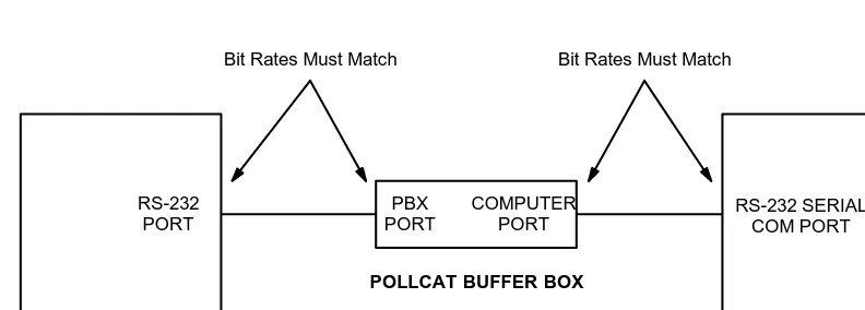
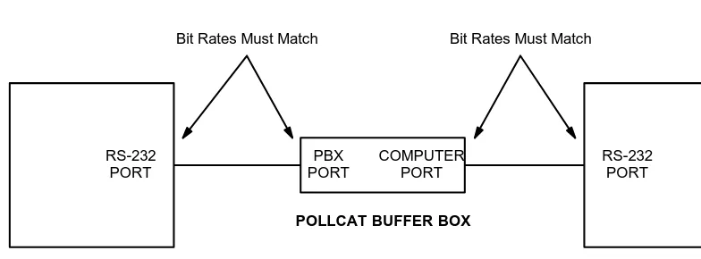
Installing the PollCat Buffer Box
The PollCat buffer box is connected to an RS-232 port on your telephone system and to a communications port on your PC, as described in the following steps (see Figure 5 on page 35):
1. Locate DIP switches 1–7 on the back of the unit.
Note: Switches 8–10 are not currently used.
2. Set the bit rate of the PC (COMPUTER) port by placing DIP switches 1, 2, and 3 in the desired positions as outlined below (D = down, U = up).
BIT RATE 1 2 3
9600 D D D
4800 U D D
2400 D U D
1200 U U D
600 D D U
300 U D U
3. Set the bit rate of the telephone system (PBX) port by placing DIP switches 4 and 5 in the desired positions as outlined below (D = down, U = up).
BIT RATE 4 5
9600 D D
2400 U D
1200 D U
300 U U
4. Set the parity (odd or even) for both ports by placing DIP switch 6 in the desired position. For odd parity, place the switch in the up position. For even parity, place the switch in the down position.
5. If installing a PollCat buffer box only (no Tandem unit), disable the X-ON/X-OFF
If a Tandem unit will also be installed, enable the X-ON/X-OFF feature for both
ports on the buffer box by placing DIP switch 7 in the up position. (The X-ON/X-OFF feature must be disabled on the Tandem unit by placing the switch in the off position.)
6. Using the appropriate cable, connect the telephone system (PBX) port on the PollCat buffer box to an RS-232 port on your telephone system. (See page 29 for connector pinout information. Also refer to the telephone system’s manual, if necessary.)
7. Using the appropriate cable, connect the PC (COMPUTER) port on the PollCat buff-er box to an available COM port on your PC. (See page 29 for connector pinout information. Also refer to the PC’s installation manual, if necessary.)
Note: If the buffer box and your PC are not at the same site, call records can be transferred to your PC using a modem. See page 46 for details.
8. Plug in the PollCat buffer box’s AC power cord and turn on the AC power switch. Clear and test the unit’s memory as outlined on page 42.
Figure 5 Buffer Box Installation
PHONE SYSTEM
POLLCAT BUFFER BOX
PERSONAL COMPUTER
PBX PORT
COMPUTER PORT
Bit Rates Must Match Bit Rates Must Match
RS-232
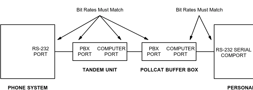
Installing the Optional Tandem Unit
To install a Tandem unit in series with the PollCat buffer box, follow these steps (see Figure 6 on the next page):
1. On the PollCat buffer box, place DIP switches 1–7 in the appropriate positions as outlined on page 34.
Note: The COMPUTER port on the PollCat buffer box and the COM port on the PC must have the same bit rate. The X-ON/X-OFF feature on the PollCat buffer box must be enabled.
2. On the Tandem unit, place DIP switches 1–7 in the appropriate positions as de-scribed for the PollCat buffer box on page 34.
Note: The RS-232 port on the telephone system, the two ports on the Tandem unit, and the PBX port on the PollCat buffer box must all have the same bit rate. Also, both the Tandem unit and the PollCat buffer box must have the same parity settings. The X-ON/X-OFF feature must be disabled on the Tandem unit.
3. On the Tandem unit, place DIP switch 8 in the up position.
4. Using the appropriate cable, connect the telephone system (PBX) port on the Tan-dem unit to an RS-232 port on the telephone system. (See page 29 for connector pinout information. Also refer to the telephone system’s manual, if necessary.)
5. Using the appropriate cable, connect the PC (COMPUTER) port on the Tandem unit to the telephone system (PBX) port on the PollCat buffer box. (See page 29 for con-nector pinout information.)
6. Using the appropriate cable, connect the PC (COMPUTER) port on the PollCat buff-er box to an available COM port on your PC. (See page 29 for connector pinout information. Also refer to the PC’s installation manual, if necessary.)
7. On each unit, plug in the AC power cord and turn on the AC power switch.
Figure 6 Tandem Unit Installation
PHONE SYSTEM
TANDEM UNIT POLLCAT BUFFER BOX
PERSONAL COMPUTER
PBX PORT
COMPUTER PORT
PBX PORT
COMPUTER PORT
Bit Rates Must Match Bit Rates Must Match
RS-232
PORT RS-232 SERIALCOMPORT
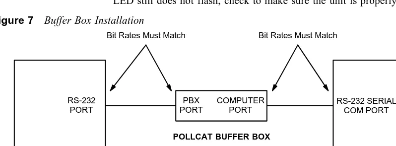
Installing the CRB Unit
The CRB unit is connected to an RS-232 port on your telephone system and to a commu-nications port on your PC, as described in the following steps (see Figure 7 on page 39):
1. Locate DIP switches 1–8 on the bottom of the unit.
2. Set the bit rate of the telephone system (PBX) port by placing DIP switches 1 and 2 in the desired positions as outlined below. Note that DIP switches are OFF when set in
the 0 position and ON when set in the 1 position.
BIT RATE 1 2
9600 ON ON
2400 OFF ON
1200 ON OFF
300 OFF OFF
3. Set the bit rate of the PC (COMPUTER) port by placing DIP switches 3 and 4 in the desired positions as outlined below.
BIT RATE 3 4
9600 ON ON
19.2k OFF ON
38.4k ON OFF
115.2k OFF OFF
4. Enable or disable the CRB unit’s “almost full” audible alarm by placing DIP switch 5 in the desired position. For no alarm, place the switch in the OFF position. To
enable the alarm, place the switch in the ON position.
5. Disable data compression (which automatically sets the data rate to 8 bits and the parity to none) by placing DIP switch 6 in the OFF position.
6. Enable the X-ON/X-OFF feature for both ports on the CRB unit by placing DIP switch 7 in the ON position.
8. Using the appropriate cable, connect the telephone system (PBX) port on the CRB unit to an RS-232 port on your telephone system. (See Figure 1 on page 12 for con-nector pinout information. Also refer to the telephone system’s manual, if neces-sary.)
9. Using the appropriate cable, connect the PC (COMPUTER) port on the CRB unit to an available COM port on your PC. (See Figure 1 on page 12 for connector pinout information. Also refer to the PC’s installation manual, if necessary.)
Note: If the buffer box and your PC are not at the same site, call records can be
transferred to your PC using a modem. See page 95 for details.
10. Plug the AC transformer cable into the 9VDC connector on the PBX end of the CRB unit. Then plug the main AC transformer unit into an available power source.
11. Clear and test the unit’s memory as follows:
a. Ensure that the CRB unit’s AC power switch is turned off.
b. While pressing the PAUSE button, turn on the AC power switch and then re-lease the PAUSE button. (The MEM and PAUSE LEDs flash.)
c. When the the memory is cleared (after about ten seconds), the unit beeps twice and the MEM LED goes out.
d. Test the unit’s ability to receive call record information by placing a valid tele-phone call on the teletele-phone system. When the call is disconnected, the PBX LED on the unit should flash to indicate that information was received from the telephone system.
Note: If the LED does not flash, reset the telephone system and try again. If the
LED still does not flash, check to make sure the unit is properly installed.
Figure 7 Buffer Box Installation
PHONE SYSTEM
POLLCAT BUFFER BOX
PERSONAL COMPUTER PBX PORT COMPUTER PORT
Bit Rates Must Match Bit Rates Must Match
RS-232 PORT
Installing the ILB Unit
The ILB unit is connected to an RS-232 port on your telephone system and to a commu-nications port on your PC, as described in the following steps (see Figure 7 on page 39):
1. Locate DIP switches 1–8 on the back of the unit.
2. Set the bit rate of the PC (COMPUTER) port by placing DIP switches 1, 2, and 3 in the desired positions as outlined in the following table.
Note: The bit rate for the COMPUTER port must match the COM port on the con-nected PC. Note that DIP switches are OFF when up and ON when down.
BIT RATE 1 2 3
1200 ON ON ON
2400 OFF ON ON
4800 ON OFF ON
9600 OFF OFF ON
19.2k ON ON OFF
38.4k OFF ON OFF
3. Set the bit rate of the telephone system (PBX) port by placing DIP switches 4 and 5 in the desired positions as outlined in the following table.
Note: The bit rate for the PBX port must match your telephone system’s RS-232 port.
BIT RATE 4 5
1200 ON ON
4800 OFF ON
9600 ON OFF
19.2k OFF OFF
5. Disable the single-line release function by placing DIP switch 7 in the ON position. When disabled, the ILB unit will release call records (continuous data transmission) until the buffer is empty or an XOFF is received. If enabled (OFF position), the ILB unit will release a single call record terminated by a Line Feed character, then wait for an XON before sending the next record.
6. Disable the optional external modem connection by placing DIP switch 8 in the ON position.
Note: If the buffer box and your PC are not at the same site, call records can be transferred to your PC using a modem. See the PollCat-ILB User’s Guide and Inside
Track User Guide for details.
7. Using the appropriate cable, connect the telephone system (PBX) port on the ILB unit to an RS-232 port on your telephone system. (See Figure 3 on page 15 for con-nector pinout information. Also refer to the telephone system’s manual, if neces-sary.)
8. Using the appropriate cable, connect the PC (COMPUTER) port on the ILB unit to an available COM port on your PC. (See Figure 3 on page 15 for connector pinout information. Also refer to the PC’s installation manual, if necessary.)
9. Plug the ILB unit into an available power source.
Clearing and Testing the Memory
For PollCat, Tandem, and CRB unit
The memory of the PollCat, Tandem or CRB unit should be cleared and tested when the unit is first installed and when memory chips are installed.
To clear and test the memory on the unit, perform these steps:
1. Turn off the AC power switch on the unit.
2. While pressing the PAUSE button, turn on the AC power switch and then release the PAUSE button. (The PAUSE, % FULL, and 80% FULL LEDs are lit.)
3. When the LEDS are unlit (after about ten seconds), the memory is cleared.
Note: If a memory error is detected, the % FULL and 80% FULL LEDs will flash alternately. The message “ERROR AT XX NNNN” is sent to the PC to indicate the bad memory location. Ensure that all of the memory chips are properly installed and securely seated. If the memory error persists, return the unit for repair.
4. Test the unit’s ability to receive call record information by placing a valid telephone call on the telephone system. When the call is disconnected, the PBX DATA LED on the unit should flash to indicate that information was received from the telephone system.
Note: If the LED does not flash, reset the telephone system and try again. If the LED still does not flash, check to make sure the unit is properly installed.
For ILB Unit
The ILB unit has different procedure for clearing and testing the memory. Follow these instructions instead.
To clear the memory on the unit, perform these steps:
CAUTION:Data cleared from memory cannot be recovered.
1. Turn off the AC power to the ILB unit.
To test the memory on the unit, perform these steps:
CAUTION:When the memory test is performed, all data will be cleared from internal memory and cannot be recovered.
1. Turn off the AC power to the ILB unit.
2. Press and hold down the ILB unit’s Default Button, turn on the AC power, and con-tinue to hold down the Default Button for at least three seconds.
3. When the “80% Full” and “Full” LEDs light to indicate starting the memory test, release the Default Button. The LEDs will blink in sequence to indicate the memory test is in progress. The test will require approximately ten seconds for each megabyte of memory.
Note: The memory test and error sequence can be aborted at any time by pressing
the Default Button.
4. The possible memory test results are:
MEMORY OK:If memory is functioning properly, the “80% Full” and “Full” LEDs will blink twice.
MEMORY FAILURE:If a memory failure is detected, the “80% Full” and “Full” LEDs will continue to blink rapidly until the Default button is pressed.
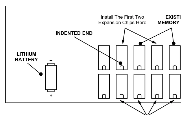
Installing Additional Memory
To install additional memory on the PollCat or Tandem unit, perform the following steps:
Caution The memory chips are extremely static sensitive. Prior to installing the chips, be sure to unplug the PollCat buffer box from the AC power source. Then ground yourself and the work area using an anti-static wrist strap.
1. Turn off the AC power switch and unplug the unit from the AC power source.
2. Remove the four screws holding the cover in place and remove the cover.
3. Remove the lithium battery.
4. Carefully insert the memory chip(s) as shown in Figure 8 on the next page. Install two chips (in the specific slots shown) for an additional 64k of memory, or install six chips for an additional 192k of memory.
Note: To avoid damaging the memory chips, be sure to install them with the indented ends pointing in the correct direction (see Figure 8).
5. While observing the polarity, replace the lithium battery.
6. Replace the cover and the screws, and plug the unit back into the AC power source.
Figure 8 PollCat Buffer Box Memory Expansion Chip Installation
Install The First Two Expansion Chips Here
Install The Second Four Expansion Chips Here
INDENTED END
–
+
LITHIUM BATTERY
Installing the Optional Modem
Rather than connecting your PC directly to the PollCat buffer box, you can extract the call records using an optional external auto-answer modem. If desired, you can purchase Inter-Tel’s optional AXXESS Modem Kit (part no. 550.3026) or an Axxent Modem Kit (part no. 520.3016) that allows you to easily connect a modem to one of the RS-232 ports on the phone system. Your PC must also be equipped with a compatible modem.
To install the modem, follow the steps beginning on page 33. However, instead of attach-ing the buffer box to your PC, attach it to the modem as shown in the figure below. For connector pinout information, see pages 29 through 31.
Figure 9 Modem Installation
PHONE SYSTEM
POLLCAT BUFFER BOX
AUTO-ANSWER MODEM
PBX PORT
COMPUTER PORT
Bit Rates Must Match Bit Rates Must Match
RS-232 PORT
AXXESSORY Talk PC and Axxent Talk
If you have an Inter-Tel AXXESS or Axxent telephone system equipped with an optional AXXESSORY Talk PC or the Axxent Talk, you can use the PC instead of a buffer box to store SMDR call records.
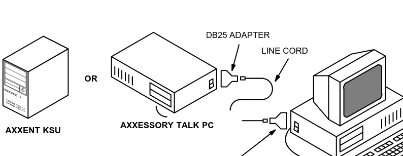
There are two ways to connect the AXXESSORY Talk PC or the Axxent Talk KSU to your PC containing the Inside Track software. One is to make your own custom cable and the other is to purchase the AXXESS/Axxent Universal RS-232 Kit. Follow the instruc-tion below.
Making Your Own Custom Cable
Make your own cables and/or adapters based on all information described in Chapter 2 — Equipment Requirements section, page 18 and 20 through 28.
Using AXXESS/Axxent Universal RS-232 Kit
Purchase the Inter-Tel AXXESS/Axxent Universal RS-232 Kit (part no. 828.1282). The kit contains a variety of cables and adapters as well as documentation that shows you how to quickly and efficiently make virtually any type of RS-232 connection.
Figure 10 AXXESSORY Talk PC and Axxent Talk KSU Installation
LINE CORD DB25 ADAPTER
YOUR PC
DB9 OR DB25 ADAPTER
AXXESSORY TALK PC AXXENT KSU
Software Installation
Installing The Inside Track Software
The Inside Track software, which is supplied on two 3½-inch floppy disks (5¼-inch disks are also available), is installed on the hard disk drive of your PC. The software is used for extracting, sorting, and reporting the call record information from the storage source (buffer box, AXXESSORY Talk PC, Inter-Tel Axxent Talk, or NetSolutions).
The following instructions assume that Windows 3.1 (or higher) software is installed on your PC and that you are familiar with Windows procedures. To install the Inside Track software, follow these steps:
1. Ensure that Windows or Windows for Workgoups (version 3.1 or higher) is running.
2. Open the Program Manager. Ensure that the Program Manager Option for “Mini-mize on use” is not enabled.
3. Insert Setup Disk 1 into the PC floppy disk drive (A or B).
4. Select the “File” pull-down menu in Program Manager. Then select “Run...” from that menu. A window with a text box appears.
5. In the Command Line text box, enter A:SETUP (or B:SETUP if the B drive is used). Then select the OK command button. A “Welcome” window appears.
6. Select the OK command button to proceed with the installation. When the Main Menu window appears, select “Install” and then select the OK command button to start the software installation.
7. When the Inside Track Setup window appears, you can change the drive or directory. Enter a new drive and/or directory in the text box, then select OK to save the new drive. (You can enter up to 32 characters, including colons and slashes.) Or, to leave the drive unchanged, select the OK command button without changing the informa-tion in the text box.
9. When the installation is complete, the PC will display several messages regarding the installation. Read each of these and then select OK to continue.
10. Remove Setup Disk 2.
11. The setup will create an Inside Track programming group that contains the Inside Track application icon and an Inside Track upgrade icon. (If an Inside Track pro-gramming group already existed, the newly installed Inside Track application icon and Inside Track upgrade icon will be added to that group.) To use the application, you must have Program Manager running. Select the Inside Track programming group and then select the Inside Track application icon. The main Inside Track screen displays and you may begin your programming session.
Note: If something goes wrong, the user has the option to install all of the drivers manu-ally. Refer to the procedure described below for Windows 3.1 and Windows 95/NT.
• Windows 3.1:Select Inside20 in the File Manager, select Windrv, and then choose Hasp.386. Copy Hasp.386 to the “C:\Windows\system.” In system.ini, under “386Enh,” add a line “device=C:\Windows\system\Hasp.386.”
• Windows 95/NT:Select Inside20 in the Windows 95/NT Exlporer, select Win32drv, and run Hinstall.exe. (You will need administrator privilege under Windows NT.)
Using Inside Track
Guidelines For Preparing and Printing Reports
To program and generate customized reports, follow these general outlines.
To Program Reports
A collection of one or more reports, and the associated SMDR (Station Message Detail Recording) and enhanced databases is called a “location.” To program a location, use the following steps:
1. Create a new location and name it using the toolbar or pull-down menu command described on page 52.
2. Indicate the type of telephone system being used and program the report information for the location, as described on page 59.
3. Set the buffer, RS-232, or raw file information as described on pages 109 through 114.
4. Program the databases for the report, as described on page 64.
To Generate And Print Reports
When you are ready to generate and print a report, follow these steps:
1. Download the call record information from the buffer as described on page 95.
2. Program the report information for the location. (This information must indicate the database that will be included in the report.) See page 64.
3. Set up the printer, as needed, following the instructions on page 87.
4. Preview the report, if desired, as described on page 88.
PULL-DOWN MENU
TOOLBAR
Toolbar And Pull-Down Menus
The toolbar at the top of the window contains tools that the you can select with a mouse to activate various menu options quickly. (A mouse is necessary for using the toolbar.) Refer to the descriptions for each of the menu options, in the following pages, for more informa-tion.
The Inside Track software has four pull-down menus that can be selected from the main screen shown above. They are: Location, System, Windows, and Help. (The Location menu is selected in the example above.) A fifth menu, Preview, is available when a report is displayed on the screen (see page 88).
The following menus and their programming screens are described in this section.
• Location
• System
• Windows
Location Pull-Down Menu
A collection of one or more reports, and the associated SMDR and enhanced databases is called a “location.” Each location has its own programming window. The location menu allows you to add, delete, edit, open, close, and save the location windows. It also allows you to set up the system-wide printer options and exit from the Inside Track software. Most of the functions in this pull-down menu are also available as command buttons in the programming windows, described in detail later, and in the tool bar (see previous page).
You can define up to 1000 locations and you can have up to 20 Location windows open at once. Each location has its own window. The Location Menu, shown in the window on the preceding page, includes the following options:
• New:The New option allows you to create a new location. A text box, like the one in the following window, prompts you for a name. Enter the name, up to 20 characters, in the text box and select the OK command button. Or, to exit without a name, select the Cancel command button.
• Edit:The Edit option allows you to edit the currently active location’s name. (This option is disabled if no locations are open.) A text box window, similar to the one shown above, shows the current name. Edit that name or enter a new name, up to 20 characters, in the text box. Then select the OK command button. Or, to exit without changing the name, select the Cancel command button.