Eco-Friendly Robotic Dredger
Swati R. Rathod
1
Department of ECE,Amaravati University, Maharashtra-445001 Email: [email protected]
Pornima P. Pawar
2Department of ECE,Amaravati University, Maharashtra-445001 Email: [email protected]
Nilesh S. Pawar
3Department of ECE,Amaravati University, Maharashtra-445001 Email: [email protected]
Prakash V.Rathod
4Department of ECE,Amaravati University, Maharashtra-445001 Email: [email protected]
Ankush Banarse
5Department of ECE,Amaravati University, Maharashtra-445001
Email: [email protected]
Abstract—
In this project we are developing such type of robot that can move wirelessly using zigbee technology . There is a wireless camera that can capture real time video of surrounding waste materials or oil and send it to control room in PC or laptop. . There is a robotic arm to pick up waste materials and a oil skimmer for removing oil in the water . This whole system of robot will work wirelessly using zigbee technology. This has significant importance as the clean and pure water for the use by the human have become very necessary due to over dumping of waste materials in water The water has become so hazardous for the use that without its cleaning it cannot be used directly.So this project has certainly got more importance nowadays.
Coming to investigation part we have found that number of policies and schemes for the cleaning and purification of the water bodies have been established by the government. Almost 21 thousand crores of rupees have been spent on the project for the Ganga river according to the survey and many others are in line. But the fact is all these schemes never got implemented in real. Many of them are still on paper awaiting for their turn. This project will definitely going to sort out all these problems for sure. All the practical problems will be eliminated in this project.
The methodologies used are very simple in this project. Wireless video module is used to see the visuals of the water body, wireless control monitoring for controlling the system and wireless pick and place arm mechanism for picking the solid waste materials in water.
1. INTRODUCTION
Water pollution is nothing but the contamination of water bodies like lakes, rivers, oceans, aquifers and groundwater. Water pollution occurs when pollutants are directly or indirectly discharged into water bodies without adequate treatment to remove harmful compounds. Everyday household activities contribute to water pollution. When it rains, fertilizer from lawns, oil from driveways, paint and solvent residues from walls and decks and even pet waste are all washed into storm sewers or nearby lakes, rivers and streams - the same lakes, rivers and streams we rely on for drinking water supply, boating, swimming and fishing.
Also since a large amount of water is polluted there is lack of usable water on earth. Now water pollution has become a major global problem which requires ongoing evaluation and revision of water resource policy at all levels. Now there is an urgent need of making the river water free from waste materials and oil spills so that a larger amount of water can be made usable. Our paper proposes a robot that can clean the floating materials and oil spills on water surface effectively. Ro-Boat is a smart river cleaning intelligent robot incorporating mechanical design and computer vision algorithm to achieve autonomous river cleaning and provide a sustainable environment. Ro-boat is designed in a modular fashion with design details such as mechanical structural design, hydrodynamic design and vibrational analysis. It is incorporated with a stable mechanical system with air and water propulsion, robotic arms and solar energy source and it is proceed to become autonomous by using computer vision.
Now why there is need of robot? Is it that we don’t have any way presently to clean water? Yes there are ways which helps to purify water reservoirs, which include chemical methods as
well physical methods. Although, we have, but these methods are not so effective. Firstly these methods are very time consuming and secondly these are expensive. The physical way by which cleaning is done the humans themselves go in water and collect the floating materials from there. Thus, there is need of some automation which will be completed by robot. Also it reduces the cost of the cleaning process. This is only single unit, we can have access over many such units by a centralised station.
2. LITERATURE SURVEY
The main objective of this project is to clean water bodies so that we can make most part of the water as useful for other important works. Now why there is need of robot? Is it that we don’t have any way presently to clean water? Yes there are ways which helps to purify water reservoirs, which include chemical methods as well physical methods. Although, we have, but these methods are not so effective. Firstly these methods are very time consuming and secondly these are expensive. The physical way by which cleaning is done the humans themselves go in water and collect the floating materials from there. Thus, there is need of some automation which will be completed by robot. Also it reduces the cost of the cleaning process.
Zigbee modules are used at both the transmitter and receiver ends for wireless transmission and reception of signals given by operator via microcontrollers. A wireless camera network is used in the robot which consists of camera transmitter planted on robot body and camera receiver placed at operating station. Camera is used to scan the area where the robot is in operation. It will capture the whole area and will make operator aware of condition of area and robot itself.
Power supplies are used to supply power to microcontrollers at both the transmitter end and receiver end. Also to supply power to robot for its motion and robotic arms, solar panel will be used. In further extension, power can be generated by the force of tides.
The robot can be used in any reservoir except high tidal regions. Whichever river we wish to clean the robot is to placed there with all the arrangements done. Only operator is required to control the robot by giving appropriate instructions. Whatever instructions operator will give (i.e. to move forward, backward, left, right or to move robotic arms up and down), to microcontrollers, the same will generate the specific corresponding voltage level to Zigbee module transmitter which will send that voltage level (instruction) to Zigbee receiver module which in turn will give it to microcontroller at receiver end and that corresponding voltage level is converted again to particular set of instructions with the help of which motor driver IC will operate motors and propellers.
This robot has many advantages and very few disadvantage. More than this it can also be used for surveillance at sea borders, in military purpose, in industry for detecting pipe leakage, in capturing snakes or other dangerous organisms, in industrial and home automation etc.
This robot will prove to be a boon to the society as it will remove the pollutants present in the rivers effectively and will make plenty of water usable for drinking purpose and other activities.
3. THEORETICAL STUDY
In theoretical study working principle, transmitter receiver section, and components required for implementation of smart robot is described below.
3.1 Working principle
The project has two ends which are Transmitter and Receiver. In transmitter side we have software named as water dredger window, which controls the motions of robot. Software consists of various instructions like forward, backward, left, right and stop. Any instruction given is converted into relevant character which is transmitted to robot through Zigbee module-CC2500. Another Zigbee module i.e. CC2500 receiver receives the character and gives to microcontroller ATMEGA 16. This microcontroller processes this character and generates combination of bits and sends to motor driver IC L293D and thus drive the robot accordingly.
FIGURE 1: SPECIMEN
3.2 Transmitter section
The transmitter end consists of Microcontroller of AVR family, Zigbee module (CC2500), power supply, keypad, camera receiver and PC unit. The power supply used is 5-8V battery. This is used to supply power to microcontroller for its working. The Microcontroller used is ATMEGA16 which is the microcontroller of AVR family. ATmega8, ATmega16, ATmega32 or ATMega64 any one can be used according to requirement. Here ATmega16 was fulfilling the requirement thus, used. It is 4 port microcontrollers having 16 KB of flash memory.
FIGURE 2: BLOCK DIAGRAM OF TRANSMITTER
This microcontroller executes most of the instructions in single execution cycle. AVRs are about 4 times faster than PICs; they consume less power and can be operated in different power saving modes. Next, the Zigbee module CC2500 is used which is used for wireless serial communication. Depending on the module of Zigbee the range of communication can be varied. Keypad is used to give instructions to the robot whether to forward, reverse, left or right. Camera with PC unit (laptop) is used to observe the area under operation thoroughly so that to take correct decisions.
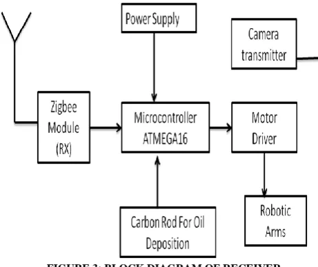
3.3 Receiver Section
In the same way we have used Zigbee module to transmit the instructions, Zigbee module is used at receiver to catch that instruction so that to give it to microcontroller for processing.
Depending on the circumstances the operator will make the necessary decisions. Also the carbon rod will be planted besides of robot to remove the oil spills from surface of water. The water when passes through the carbon rods, the oil from that will be soaked from it and will leave the water purified. The power supply is used to provide power to microcontroller and motor driver IC. To provide power to motors, high voltage is required which will be provided by solar panel.
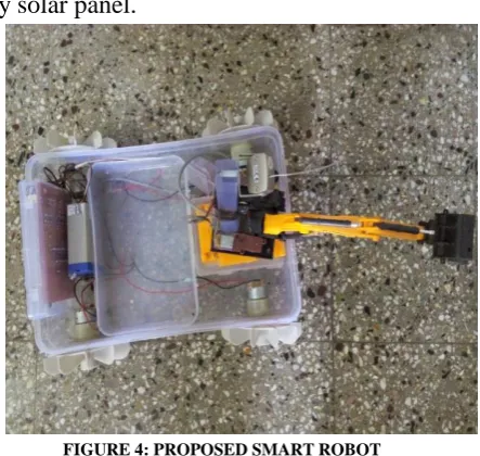
FIGURE 4: PROPOSED SMART ROBOT
3.4. Hardware Component Description
To know how the robot will work, first it is important to well about the components used for its making. The descriptions of some of the components are given below.
3.4.1. AVR Microcontroller
Microcontroller can be termed as a single on chip computer which includes number of peripherals like RAM, EEPROM, Timers etc., required to perform some predefined task. There are number of popular families of microcontrollers which are used in different applications as per their capability and feasibility to perform the desired task, most common of these are 8051, AVR and PIC microcontrollers. In this article we will introduce you with AVR family of microcontrollers.
FIGURE 5: AVR MICROCONTROLLER
The ATmega16 is a low-power CMOS 8-bit microcontroller based on the AVR enhanced RISC architecture. AVR is a modified Harvard architecture 8 bit RISC single chip microcontroller which was developed by Atmel in 1996. AT mega 16 is high performance low power Atmel AVR 8bit microcontroller with 8kb of in system self programmable memory. There are 131 powerful instructions present in ATmega16.Most of single clock cycle execution and 32*8 general purpose working register, fully static operation.
FIGURE 6: ATMEGA16
3.4.1.1. Features
High-performance, Low-power AVR 8-bit Microcontroller.
Advanced RISC Architecture.
32 x 8 General Purpose Working Registers. On-chip 2-cycle Multiplier.
Two 8-bit Timer/Counters with Separate Prescalers and Compare Modes.
One 16-bit Timer/Counter with Separate Prescaler.
Four PWM Channels 8-channel, 10-bit ADC Byte-oriented Two-wire Serial Interface. Special Microcontroller Features Power-on
Reset and Programmable Brown-out Detection.
External and Internal Interrupt Sources. I/O and Packages.
32 Programmable I/O Lines.
40-pin PDIP, 44-lead TQFP, and 44-pad MLF.
Operating Voltages 4.5 - 5.5V for ATmega16.
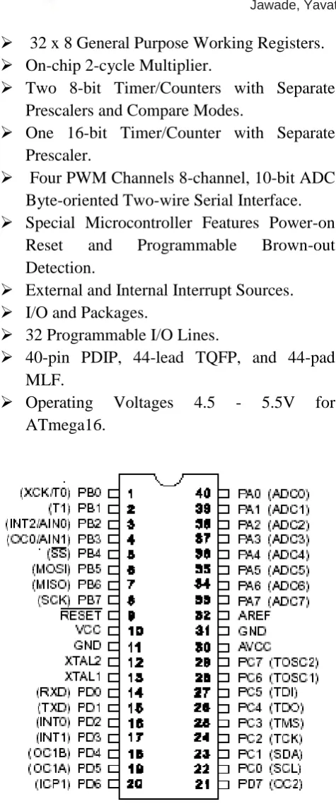
FIGURE 7: PIN DIAGRAM OF MICROCONTROLLER 3.4.1.2. Pin Description
VCCDigital supply voltage.
GND Ground.
Port A (PA7…..PA0)Port A serves as the analog inputs to the A/D Converter. Port A also serves as an 8-bit bi-directional I/O port, if the A/D Converter is not used. Port pins can provide internal pull-up resistors (selected for each bit). The Port A output buffers have symmetrical drive characteristics with both high sink and source capability. When pins PA0 to PA7 are used as inputs and are externally pulled low, they will source current if the internal pull-up resistors are activated. The Port A pins are tri-stated when a reset condition becomes active, even if the clock is not running.
Port B (PB7...PB0) Port B is an 8-bit bi-directional I/O port with internal pull-up resistors (selected for each bit).
Port B output buffers have symmetrical drive characteristics with both high sink and source capability. As inputs, Port B pins that are externally pulled low will source current if the pull-up resistors are activated. The Port B pins are tri-stated when a reset condition becomes active, even if the clock is not running .Port B also serves the functions of various special features of the ATmega16.
JTAG interface is enabled, the pull-up resistors on pins PC5 (TDI), PC3 (TMS) and PC2 (TCK) will be activated even if a reset occurs. Port C also serves the functions of the JTAG interface and other special features of the AT mega.
Port D (PD7..PD0)Port D is an 8-bit bi-directional I/O port with internal pull-up resistors (selected for each bit). The Port D output buffers have symmetrical drive characteristics with both high sink and source capability. As inputs, Port D pins that are externally pulled low will source current if the pull-up resistors are activated.
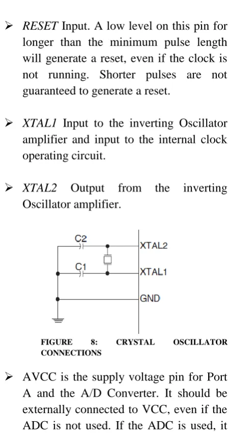
RESET Input. A low level on this pin for longer than the minimum pulse length will generate a reset, even if the clock is not running. Shorter pulses are not guaranteed to generate a reset.
XTAL1 Input to the inverting Oscillator amplifier and input to the internal clock operating circuit.
XTAL2 Output from the inverting Oscillator amplifier.
FIGURE 8: CRYSTAL OSCILLATOR CONNECTIONS
AVCC is the supply voltage pin for Port A and the A/D Converter. It should be externally connected to VCC, even if the ADC is not used. If the ADC is used, it
should be connected to VCC through a low-pass filter.
AREF is the analog reference pin for the A/D Converter.
3.4.2 Zigbee technology
IEEE address, the Network Address and all known network addresses.
FIGURE 9: ZIGBEE NETWORK
Device bindings which are logical links between end devices can be created like binding of a Lamp Application Object with a Switch Application Object. The Radio unit and the Processing unit are often built into a single chip to reduce costs. When a car enters the premises, the radio transmitter inside the car broadcasts its presence to the Zigbee Coordinator through routers. The coordinator then binds the garage shutter’s receiver with the Car’s transmitter and all packets from the Car transmitter are routed to the Shutter, which can then open and close without stepping out of the car. The whole transaction can be automated such that by the time the car reaches the garage door, it automatically opens.
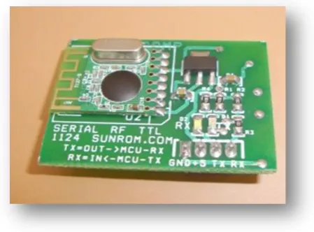
3.4.2.1 CC2500 Transceiver
This RF Module can be used for applications that need two way or Multiway wireless data transmission. It features MultiMaster and MultiSlave and reliable transmission, Small Size and best range in its class protocol is self controlled and completely transparent to user interface. The module can be embedded to your current design so that wireless communication can be set up easily for wireless
data transmission. It supports adjustable data rate with reliable transmission distance.
FIGURE 10: CC2500
Features:
Automatic switching between TX and RX mode.
FSK technology, half duplex mode, robust to interference.
2.4 GHz band, no need to apply frequency usage license.
Protocol translation is self controlled, easy to use.
High sensitivity, reliable transmission range. Standard UART interface, TTL (3-5V) logic
level.
Stable, small size, easier mounting. No tuning required, PLL based self tuned. Error checking (CRC) of data in built.
Applications:
Sensor Networks / Data collection. Wireless metering.
Access control / Identity discrimination. Home Automation.
Smart house products / Security Systems. Remote control / Remote measurement
system.
Weather stations.
Multi Slave Communication.
3.4.3. Camera
Wireless security cameras provide surveillance for homes or businesses. The uses of these cameras vary; those with remote access allow users to monitor activity inside of their homes to view interaction between caregivers and a child or to monitor children home alone. Outdoor cameras provide additional security by allowing users to view visitors at the door before opening it and to monitor perimeters of their home and grounds. Businesses rely on these cameras as well. Many wireless security cameras have motion and sound sensors that send out alerts to the user if the sensor triggers. Wireless cameras also allow users to install them in areas where wired security systems are not feasible. Knowing about the varied features offered by wireless security cameras allows consumers to make an informed decision before purchasing one.
Wireless security cameras, alone or as part of a more extensive security system, are advantageous because of their ease in installation and the ability to place them in locations where wired cameras might not be an option. The cameras produce images that are viewable on monitors or computers; some cell phones also work with the cameras. While making a home more secure is one use for wireless security cameras, they serve other functions as well, many of which are indoors. These include monitoring babies, viewing the interactions between caregivers and children, and monitoring children who are at home by themselves.
Features of camera:
The wireless A/V transmitter system contains 8-15 channels 2.4G/1.2G transmitter. The AV output can be connected to TV for
real-time viewing.
The wireless system offers up to 7000m.
It is equipped with audio.
The wireless transmitter, wireless receiver offers digital display.
The receiver features high receiving sensitivity.
The wireless transmitter, wireless receiver offers convenience and credibility.
Applications of camera:
The wireless transmitter, wireless receiver with many working channels is used for far distance wireless surveillance projects.
FIGURE 11: CAMERA TRANSMITTER-RECEIVER PAIR
In addition to the wireless transmitter, wireless receiver, we can supply many other CCTV cameras, including IR camera, dome camera, box camera, etc.
3.4.4. Robotic Arm
perform tasks such as "pick and place," which is literally picking something up and placing it elsewhere. Robotic arm is used for wireless pick and place mechanism.
FIGURE 12: ROBOTIC ARM
3.4.5. DC Motor
A DC motor is an electric motor that runs on direct current (DC) electricity. DC motors were used to run machinery, often eliminating the need for a local steam engine or internal combustion engine. DC motors can operate directly from rechargeable batteries, providing the motive power.
FIGURE 13: DC MOTORS
3.4.6. USB to TTL Converter
FIGURE 14: USB TO TTL CONVERTER
The USB TTL Serial cables are a range of USB to serial converter cables which provide connectivity between USB and serial UART interfaces. A range of cables are available offering connectivity at 5V, 3.3V or user specified signal levels with various connectors. All cables feature an FTDI FT232R device integrated within the cable USB type ‘A’ connector, which provide access to UART Transmit (Tx), Receive (Rx), RTS#, CTS#, VCC (5V) and GND connections. All cables are fully RoHS compliant and are FCC/CE approved.
All cables are 1.8m in length. A USB adapter is a type of protocol converter which is used for converting USB data signals to and from other communications standards. Commonly, USB adaptors are used to convert USB data to standard serial port data and vice versa.
Most commonly the USB data signals are
converted to
The primary application scenario is to enable USB based computers to access and communicate with serial devices featuring D-Sub (usually DB9 or DB25) connectors or screw terminals, where security of the data transmission is not generally an issue.
USB serial adapters can be isolated or non-isolated. The isolated version has opto-couplers and/or surge suppressors to prevent static electricity or other high-voltage surges to enter the data lines thereby preventing data loss and damage to the adapter and connected serial device. The non-isolated version has no protection against static electricity or voltage surges, which is why this version is usually recommended for only non-critical applications and at short communication ranges.
4. EXPERIMENTAL STUDY
4.1. Flash Magic
Flash magic is used to program the microcontroller. Philips provides a ready-made FLASH In System Programming Utility for the PC, which can be used to program the development board. Using FLASH Magic, we will be able to perform different operations to a microcontroller device, operations like erasing, programming and reading flash memory, modifying the Boot Vector, performing a blank check on a section of the flash memory and many others.
System configuration requirements for flash magic are windows 95/98/ME/NT/2000/XP/Vista, 16MB RAM, 3MB Disk space.
4.2. Embedded C
The programming language used here is an Embedded C. This embedded C language is different from the generic c language in few
things like Data types, Access over the architecture addresses.
The Embedded C programming language forms the user friendly language with access over Port addresses, SFR Register addresses etc. Embedded C use most of the syntax and semantics of standard C, example: main() function, variable definition, data-type declaration, conditional statements(if, switch. case), loops(while, for), fuctions, arrays and strings, structures and unions, bit operations, macros, etc.
4.3. Keil u Vision IDE
u vision3 is an Integrated Development Environment that helps to write, compile, and debug embedded programs. The keil software development tools are designed to solve the complex problems facing embedded software developers. When starting a new project, simply select microcontroller device database and the u vision IDE sets all compiler, assembler, linker, and memory options.
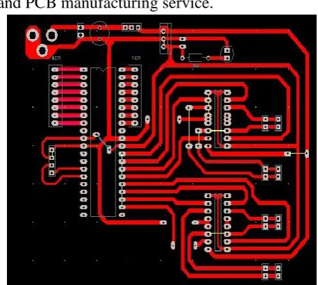
4.4 PCB Artist
PCB Artist is a circuit design software and PCB manufacturing service.
4.5. Water dredger window
This software is used to control the robot. It contains various instructions like and forward, backward, left, right, pick, clockwise, counter-clockwise and stop. This software converts the given instruction into particular character which is further send to zigbee module. This software is programmed using dotnet.
FIGURE 16: WATER DREDGER WINDOW
4.6. TV Home media
This software enables to view the area being cleaned on PC unit.
FIGURE 17: TV HOME MEDIA
5. RESULTS AND DISCUSSION
Thus, the problem of water pollution which has been increased to a wide area of earth, now can be controlled to some extent with the help of this smart robot. If this project is established on a large scale, then water bodies can be cleaned efficiently. The components used in this project are very cheap and are readily available. Due to this, project can be made commercially. If we want to use the project on large scale, some modifications will be required in the project like the source of power supply should be switched to solar panel.
On using this project on large scale the cost will not increase so much but the water bodies can be cleaned effectively.
5.1 Advantages
Remove oil and other floating materials from water.
High Intelligence, Flexibility and mobility.
Provides marine disaster warning and prevention.
Fast response, low power consumption. Can generate electricity from tides, if
used in Sea.
Assessing offshore environment pollution.
5.2Disadvantage
During high tides in sea, robot cannot work properly.
If solar panel is used as a source of power supply, then robot will not word in cloudy or bad weather.
5.3 Applications
In military purpose.
In industry detecting pipe leakage. Snake capturing.
6. CONCLUSION AND FUTURE SCOPE
6.1. Conclusion
With this we can conclude that the system which has developed by using controller ATMEGA16 AVR in a tiny 40 pin DIP package can be really used in a real time environment. But there are some limitations and constraints which we have looked into .If this project is established into large scale then to a great extent water bodies can be cleaned.
6.2. Future scope
We can extend our project by making it work in real time environment. On a large scale, solar panels can be used which will keep robot energized. Alternatively, energy can be
generated from tides .Carbon rods can be used which will soak oil from water. This robot can be very useful during floods.
7. REFERENCES
[1] 8051 and AVR Architecture and programming by Mazidi, ‘Real world interfacing’.
[2]www.zigbee.com
[3]www.alldatasheets.com
[4]www.electronicsforyou.com