TOSHIBA
STRATA DK
Strata DK Release 2 & 3
DK24 – DK56 – DK96
I
PUBLICATION INFORMATION
z-. -.
.
Toshiba America Information Systems, Inc., Telecommunication Systems Division, reserves the right, without prior notice, to revise this information publication for any reason, including, but not limited to, utilization of new advances in the state of technical arts or to simply change the design of this document.
Further, Toshiba America Information Systems, Inc., Telecommunication Systems Division,
also reserves the right without prior notice, to make such changes in equipment design or components as engineering or manufacturing methods may warrant.
WARRANTY
Toshiba America Information Systems, Inc., (“TAIS”) warrants that this telephone equipment (except for fuses, lamps, and other consumables) will, upon delivery by TAIS or an authorized TAlS dealer to a retail customer in new condition, be free from defects in material and workmanship for twelve (12) months after delivery. This warranty is void (a) if the equipment is used under other than normal use and maintenance conditions, (b) if the equipment is modified or altered, unless the modification or alteration is expressly authorized by TAIS, (c) if the equipment is subject to abuse, neglect, lightning, electrical fault, or accident, (d) if the equipment is repaired by someone other than TAIS or an authorized TAIS dealer, (e) if the equipment is defaced or missing, or (f) if the equipment is installed or used in combination or in assembly with products not supplied by TAIS and which are not compatible or are of inferior quality, design, or performance.
The sole obligation of TAIS or Toshiba Corporation under this warranty, or under any other legal obligation with respect to the equipment, is the repair or replacement by TAIS or its authorized dealer, with new or refurbished parts (at their option) of such defective or missing parts as are causing the malfunction. If TAIS or one of its authorized dealers does not replace or repair such parts, the retail customer’s sole remedy will be a refund of the price charged by TAIS to its dealers for such parts as are proven to be defective, and which are returned to TAlS through one of its authorized dealers within the warranty period and no later than thirty (30) days after such malfunction, whichever first occurs. Under no circumstances will the retail Customer or any user or dealer or other person be entitled to any direct, special, indirect, consequential, or exemplary damages, for breach of contract, tort, or otherwise. Under no circumstances will any such person be entitled to any sum greater than the purchase price paid for the item of equipment that is malfunctioning.
To obtain service under this warranty, the retail customer must bring the malfunction of the machine to the attention of one of TAIS authorized dealers within the twelve (12) month period and no later than thirty (30) days after such malfunction, whichever first occurs. Failure to bring the malfunction to the attention of an authorized TAIS dealer within the prescribed time results in the customer being not entitled to warranty service.
THEREARENOOTHERWARRANTlESFROMElTHERTOSHlBAAMERlCAINFORMATlON
SYSTEMS, INC., OR TOSHIBA CORPORATION WHICH EXTEND BEYOND THE FACE OF THIS WARRANTY.ALLOTHERWARRANTlES,EXPRESSORlMPLlED,lNCLUDlNGTHEWARRANTlES
OF MERCHANTABILITY, FITNESS FOR A PARTICULAR PURPOSE, AND FITNESS FOR USE, ARE EXCLUDED.
STRATA DK
GENERAL END USER INFORMATION
The STRATA DK Electronic Digital Key telephone systems
are registered in accordance with the provisions of Part 68 of
the Federal Communications Commission’s Rules and Regu-
lations.
FCC REQUIREMENTS
Means of Connection: The Federal Communications Com-
mission (FCC) has established rules which permit the
STRATA DK system to be connected directly to the tele-
phone network. Connection points are provided by the
telephone company-connections for this type of cus-
tomer-provided equipment will not be provided on coin
lines. Connections to party lines are subject to state tariffs.
Incidence of Harm: If the system is malfunctioning, it may
also be disrupting the telephone network. The system
should be disconnected until the problem can be deter-
mined and repaired. If this is not done, the telephone
company may temporarily disconnect service. If possible,
they will notify you in advance, but, if advance notice is not
practical, you will be notified as soon as possible. You will
be informed of your right to file a complaint with the FCC.
Service or Repair: For service or repair, contact your local
Toshiba telecommunications distributor. To obtain the
nearest Toshiba telecommunications distributor in your
area, call Toshiba America Information Systems, Inc.,
Telecommunication Systems Division in Irvine, CA (714)
583-3700.
Telephone Network Compatibility: The telephone company
may make changes in its facilities, equipment, operations,
and procedures. If such changes affect the compatibility or
use of the STRATA DK system, the telephone company will
notify you in advance to give you an opportunity to maintain
uninterrupted service.
Notification of Telephone Company: Before connecting a
STRATA DK system to the telephone network, the tele-
phone company may request the following:
1) Your telephone number.
2) FCC registration number:
l STRATA DK may be configured as a Key or Hybrid
telephone system. The appropriate configuration for
your system is dependent upon your operation of the
system.
l If the operation of your system is only manual selec-
tion of outgoing lines, it may be registered as a Key
telephone system.
l If your operation requires automatic selection of out-
going lines, such as dial access, Least Cost Routing, Pooled Line Buttons, etc., the system must be regis-
tered-as a Hybrid telephone system. In addition to the
above, certain features (TIE Lines, Off-premises
Stations, etc.) may also require Hybrid telephone
system registration in some areas.
l If you are unsure of your type of operation and/or the
appropriate FCC registration number, contact your
local Toshiba telecommunications distributor for as-
sistance.
DKSU Manufactured in Japan
Key system: CJ69XA-10242-KF-E Hybrid system: CJ69XA-10243-MF-E
DKSU Manufactured in USA as of November 1989
Key system: CJ687N-10578-KF-E Hybrid system: CJ687N-10579-MF-E
3) Ringer equivalence number: 0.28 (see Table A). The
ringer equivalence number (REN) is useful to determine
the quantity of devices which you may connect to your
telephone line and still have all of those devices ring when
your number is called. In most areas, but not all, the sum
of the RENs of all devices connected to one line should not
exceed five (5.08). To be certain of the number of devices
you may connect to your line, as determined by the REN,
you should contact your local telephone company to ascer-
tain the maximum REN for your calling area.
4) Network connection information USOC jack required:
RJ14C, RJ2EX, RJPGX, RJ21X (see Table A). Items 2,3
and 4 are also indicated on the equipment label.
RADIO FREQUENCY INTERFERENCE
Warning: This equipment generates, uses, and can radi-
ate radio frequency energy and if not installed and used in
accordance with the manufacturer’s instruction manual, may
cause interference to radio communications. It has been
tested and found to comply with the limits for a Class A
computing device pursuant to Subpart J of Part 15 of FCC
Rules, which are designed to provide reasonable protection
against such interference when operated in a commercial
environment. Operation of this equipment in a residential area
is likely to cause interference; in which case, the user, at his
own expense, will be required to take whatever measuresrnay
be required to correct the interference.
This system is listed with Underwriters Laboratory.
LISTED
0
!L
49L7 E89891
IMPORTANT NOTICE - MUSIC-ON-HOLD
In accordance with U.S. Copyright Law, a license may be required from the American Society of Composers, Authors and
Publishers, or other similar organization, if radio or TV broadcasts are transmitted through themusic-on:hold feature of this
telecommunication system. Toshiba America Information Systems, Inc., hereby disclaims any liability arising out of the failure to
StrataExr
7
STRATA DK
GENERAL DESCRIPTION
DECEMBER 1990
b *)
PARAGRAPH
1
2 3 4TABLE
A
B
C
D
E
F
G
H
I
J
K
L
M
N
0
P
TABLE OF CONTENTS
SUBJECT
TABLE of CONTENTS ...
GENERAL ...
Summary ...
Technology ...
Maintenance and Programming ...
PERIPHERAL HARDWARE DESCRIPTIONS ...
Digital Telephones ...
Electronic Telephones ...
Toshiba Peripherals ...
Customer-supplied Peripherals ...
SYSTEM HARDWARE DESCRIPTION ... . ...
Key Service Units ...
System Operation ...
Printed Circuit Boards ...
System Capacity and Configuration ...
FEATURES ...
System Features ...
Digital and Electronic Telephone Features.. ...
GLOSSARY OF ACRONYMS ...
TABLE LIST
SUBJECT
MAXIMUM CONFIGURATIONS ...
GENERAL REQUIREMENTS ...
RESERVE POWER TIME ...
DATA INTERFACE SPECIFICATIONS ...
STATION LOOP REQUIREMENTS ...
NETWORK REQUIREMENTS ...
SYSTEM TON ES ...
COMMON CONTROL INFORMATION ...
OPTIONAL INTERFACE PCB OPTIONS ...
SYSTEM CAPACITIES ...
UNIVERSAL SLOT CONFIGURATIONS ...
OPTIONAL SUBASSEMBLIES ...
OPTIONAL UNITS ...
SYSTEM FEATURES ...
DIGITAL AND ELECTRONIC TELEPHONE FEATURES.. ...
STANDARD TELEPHONE FEATURES.. ...
i
1
1
1
3 3 3 7 9 13 1313 -
DECEMBER 1990
TABLE OF CONTENTS (continued)
*-.
FIGURE LIST
-.
FIGURE NO.
1 2 3 4 5 6 7 8 9 IO 11 12 13 14 15 16 17 18A 188 19 20
SUBJECT
PAGE
STRATA DK
PERIPHERALS
...
...
III
STRATA DK24,
DK56,and DK96 CABINETS ...
1
20-button DIGITAL TELEPHONE ... 5
20-button LIQUID CRYSTAL DISPLAY DIGITAL TELEPHONE.. ... 5
INTEGRATED DATA INTERFACE UNIT (PDIU-DI) ... 6
DIGITAL DIRECT STATION SELECTION CONSOLE ... 7
1 O-button ELECTRONIC TELEPHONE ... 8
20-button ELECTRONIC TELEPHONE ... 8
20-h&m
LIQUID CRYSTAL DISPLAY ELECTRONIC TELEPHONE ... 8DIRECT STATION SELECTION CONSOLE ... 9
STAND-ALONE DATA INTERFACE UNIT (PDIU-DS) ... 9
DOOR
PHONE ...
11DOOR PHONE/LOCK CONTROL UNIT (HDCB) ... 11
EXTERNAL SPEAKER (HESB) ...
12DK24 CABINET INTERIOR ... 15
DK56 CABINET INTERIOR ... 16
DK96 CABINET INTERIOR ... 16
DK FUNCTIONAL BLOCK DIAGRAM ... 18
DK FUNCTIONAL BLOCK DIAGRAM ... 19
DIGITAL TELEPHONE DIAGRAM ... 46
ELECTRONIC TELEPHONE DIAGRAM.. ... 47
1 GENERAL
Summary
STRATA DK digital key telephone systems are
advanced key/hybrids that are electrically com-
patible with the public telephone network (loop
start CO lines and E & M TIE lines) and can
function in PBX or Centrex environments.
NOTE:
Every time “CO line” is mentioned hereafter,
the information also applies to Centrex and
PBX lines.
Each system can be configured as key or
hybrid, with separate Federal Communications
Commission registration numbers for each type.
The appropriate configuration for an individual
system depends on its function.
STRATA DK24, DK56, and DK96 models are
very similar in design. Figure 1 illustrates the
impressive range of basic features and options
available on all three systems; Figure 2 shows
the cabinets and their relative sizes. To accom-
modate a wide variety of users’ application and
expansion needs, system cabinet configurations
are extremely flexible.
FIGURE
L-STRATA DK24, DK56, and
DK96 CABINETS
The functional difference between models is
primarily one of capacity (see Table A). STRATA
DK24 can be configured in possible combina-
tions extending from 32 stations and 8 CO lines
to a square system of 16 X- 16.’ STRATA DK56
can be configured in possible combinations
extending from 56 stations and 4 CO lines to 24
stations and 20 CO li:tes. STRATA DK96 combi-
nations extend from 96 stations and 8 CO lines
to 40 stations and 36 CO lines (see Table A).
Toshiba digital telephones are connected to
the system with l-pair cabling. With a 2B+D
ISDN-type digital link, this single pair transmits
and receives simultaneous voice and data along
with control information. Toshiba electronic tele-
phones are connected to the system with 2-pair
cabling, and can access most of the same
advanced features as the digital telephones.
Solid-state digital electronics inside the key serv-
ice unit translate digital signals from the electron-
ic and digital telephone dialpads into either
DTMF tones or rotary dial signals, depending on
the central office’s requirements (see Peripheral
Hardware Descriptions). Many customer-sup-
plied standard telephones and auto attendant/
voice mail devices are also compatible with the
systems, because the systems provide end-to-
end DTMF signaling between digital and elec-
tronic telephones and devices connected to
standard telephone ports.
Technology
STRATA DK digital key telephone systems
apply the following technology:
Pulse Code Modulation: The system is com-
pletely digital. Therefore, talk paths operate
through digital switching, as opposed to ana-
log crosspoints. Analog-to-digital and digital-
to-analog conversion
is accomplished
by
CODECs on station and CO line PCBs. Pulse
Code Modulation technology allows fully non-
blocking intercom and outside line talk paths.
Stored Program Control: The system uses a
16-bit microprocessor to achieve stored pro-
gram control. System operating software is
stored in read only memory (ROM). The sys-
tem’s individual configuration and custom pro-
I:
1,
STRATA DK
j
GENERAL DESCRIPTION
i
DECEMBER 1990
TABLE A
MAXIMUM CONFIGURATIONS
1
40 36 32 28 24 AVAILABLE
CO LINES 20 16 8 4
DK24 (PCTUS) DK24 (PCTU)4
0 8 1624324048566472808896
AVAILABLE STATION PORTS
Maximum Configurations
DK56
CO lines Stations
20 24 16 32
l-l
12 408 48 4 56
DI 96
CO lines
36 40 32 48 28 56 24 64 20 72 16 80 12 88 8 96
Stations
NOTES:
1. The above station capacities apply to any combination of standard telephones, 6500-series
electronic telephones, and IOOO-series digital telephones. Station capacities using older
Toshiba electronic telephones are given in STRATA DK installation documentation.
2.
installing a TIE line (PEMU) PCB or an optional interface (PIOU, PIOUS, or PEW) PCB
reduces available CO lines by four or available ports by eight.
3. The DK24’s 32-station limit is a result of power supply capacity.
4. PCTUZ or PCTU3.
I
grarnming is stored in random access memory
(RAM). RAM
is protected by a lithium battery,
which has at least a six year life span.
Microprocessors:
The system’s main micropro-
cessor is a 16-bit 68000-type that operates at
a clock speed of 8 MHz. It is located on the
system’s control board (PCTU). Local micro-
processors are located on all printed circuit
boards. The local microprocessor is an 8-bit
TMP90C840-type
that operates at a clock
speed of 10 MHz.
Custom Electronic Circuitry: Use of large scale
integration (LSI) technology enables STRATA
DK circuit design to be simple and efficient.
More circuitry fits onto smaller printed circuit
boards (PCBs) and affords a compact system.
Widespread use of CMOS circuits minimize
the system’s power requirements.
Power Supply: The system uses a switching-
type power supply to generate *5VDC and
-24VDC. Mechanical circuit breakers on the
front panel, which may be reset if necessary,
protect these DC voltages.(See Table B for
General Requirements).
l
The source of the power used is a stan-
dard 117VAC, 15 amp circuit. The power
supply has a built-in battery charger to
maintain customer-supplied
batteries
which can be connected as a backup. This
allows full normal system operation for a
number of hours in the event of a primary
power failure. (For more detail, see Table
Q
Maiqtenance and Programming
As a result of large scale integrated circuitry,
STRATA DK
telephone systems have a minimal
number of printed circuit board types. Less time
is spent isolating board failures. This directly
translates to saving time and money.
Hardware maintenance and repair procedures
describe how to quickly and easily locate,
remove, and replace defective modules, with
minimal or no system downtime.
A remote administration -and ma’intenance
option can be added to install and maintain cus-
tomer software, and to test hardware from
remote locations.
On-site maintenance and programming
is
accomplished using:
l
The 20-button LCD digital or electronic
telephone designated for programming
and maintenance, always connected to
station port 05. This telephone may be
used as a normal station when not used
for programming.
-or-
* An on-site ASCII terminal connected to an
optional maintenance port.
2 PERIPHERAL
HARDWARE
DESCRIPTIONS
A wide variety of peripheral equipment is com-
patible with all three systems (see Figure 1).
Peripherals fall under four different categories:
digital telephones,
electronic
telephones,
Toshiba-supplied peripherals, or customer-sup-
plied peripherals. This section describes the
Toshiba-supplied equipment. When applicable,
system interface information is included.
Digital Telephonest
There are two digital telephone models avail-
able. The phones are enclosed in a stylish,
impact-resistant case with a charcoal gray matte
finish, and blend easily into any progressive
office environment.
Both digital telephone models and the digital
DSS console (see Digital Direct Station Selection
Console) have the same dimensions:
Height: 3.6 in. (92 mm)
Width: 7.3 in. (184 mm)
Length: 9.0 in. (229 mm)
In standard form, all digital telephones may be
wall mounted without additional equipment and
are hearing aid compatible.
t Requires Release 3 software.
-3-
STRATA
DK
GENERAL
DESCRIPTION
DECEMBER
1990
TABLE
B
GENERAL
REQUIREMENTS
-.
Primary power Input AC AC frequency DK24 power supply DK56 power supply DK96 power supply
Environmental specifications
Operating temperature Operating humidity Storage temperature Power supply
DC voltage output specification
a5 w 135VAC 50/60 Hz
65 watts 140 watts 230 watts
32 ..a 104°F (0 - 40°C)
20 - 60% relative humidity without condensation - 4 M 158°F (-20 M 70°C)
-24VDC: (-26.3 w -27.8VDC) +5VDC: (+4.5 w +5.5VDC) - 5VDC: (- 4.5 m - 5.5VDC)
Battery charger characteristics
PSTU or PESU (circuits 1 & 2)
Ring voltage
Charger: current limiting
Nominal float voltage: 2.275 volts/cell Charge current: 0.7 amps maximum
Battery discharge cut-off voltage: 20.5 +_ 0.5VDC
Square wave output with high/low option jumper:
Low position, 130 + 20VDC peak-to-peak (no-load)
High position, 190 + 25VDC peak-to-peak (no-load)
Ringing capability
PEW or PSTU modem interface data rate
BTU rating DK24
Two ringers maximum per circuit, high or low position
9600 bps maximum
PART QTY
PEKU 3 103 BTUs (30 watt hours)
PCOU 2
PCTUS 1
PIOUS 1
EKTs 24
DK56 PEKU 5
PCOU 3
PCTU 1
EKTs 40
205 BTUs (60 watt hours)
DK96 PEKU 9
PCOU 5
PCTU 1
EKTs 72
346 BTUs (102 watt hours)
TABLE
C
RESERVE
POWER
TIME
TYPICAL RESERVE POWER DURATION ESTIMATES
*
Time is estimated with the following considerations: 1. Batteries have full charge at start of operation.
2. Batteries (2) are connected in series.
8. Batteries are 12VDC, rated at 80 amp/hours each. 4. System is operating at full load traffic with LCD phones.
5. Batteries used for this test are gel-Cell and maintenance-free. Reserve duration will vary &pending
upon battery type, age, and manufacturer. These figures should only be used as an estimate.
Each digital telephone also features a
standard modular handset cord and is connected
to the system with a single-pair modular line cord
which can transmit and receive simultaneous
voice and data.
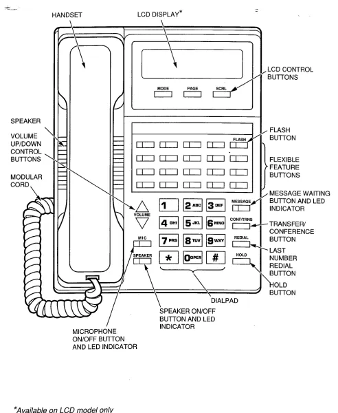
20-button Digital Telephone (Figure 3):
The1020H provides handsfree answerback capa-
bilitv on intercom lines.
FIGURE
3-20-button DIGITAL
TELEPHONE
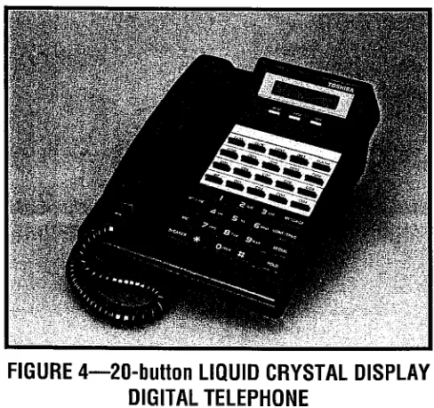
20-button
Liquid Crystal
Display
Digital
Telephone (Figure
4): The 1020SD is avail-able as a full speakerphone with a 32-charac-
ter, alphanumeric liquid crystal display (LCD)
field. The numerous LCD features include:
l Alphanumeric Messaging
l Called Station Messaging
l Calling Station Messaging
l Busy Station Messagingt
l Group/Remote Station Messaging?
l Busy Lamp Field (BLF) Indication
l CO line Identification
l Speed Dial Memo
l Timed Reminders with Messaging
l Intercom User Name/Number Display
l Call Duration Display
l DateiTime of Day
l Call Progress Information
FIGURE
4-20-button LIQUID CRYSTAL
DISPLAY
DIGITAL
TELEPHONE
Digital Telephone Upgrade Options:
DigitalTelephones can be upgraded to transmit and
receive simultaneous voice and data. They
t Requires Release 3 software.
STRATA DK
GENERAL DESCRIPTION
DECEMBER 1990
can also be upgraded with off-hook call
anounce, loud ringing bell, and headset inter-
face capability.
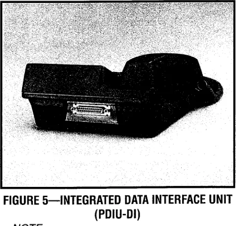
l
Simultaneous
Voice and Data: Digital
telephones may be upgraded with an inte-
grated data interface unit (PDIU-DI) to
receive and transmit simultaneous voice
and data; data and voice calls can be
made independently of each other. The
PDIU-DI (Figure 5) is easily installed,
replacing the usual digital telephone base.
Asynchronous data devices, such as per-
sonal computers and terminals, can be
connected to the standard RS-232 connec-
tor of the PDIU-DI. Station users are able
to transmit and receive RS-232 data over
the PDIU-DI-equipped digital telephone’s
single twisted wire pair. 2B+D technology
enables the digital telephone and the
PDIU-DI to share the same wire pair and
station port (see Table D).
FIGURE 54NTEGRATED DATA INTERFACE UNIT
(PDIU-DI)
NOTE:
The PDIU-DI will function with all slots,
except slots 11 w 14 in DK96.
l
Off-hook
Call Announce
Upgrade: If
equipped with an off-hook call announce
(OCA) upgrade assembly, each digital tele-
phone may receive intercom calls when
the handset is off-hook.
l
The OCA upgrade assembly for digital
t Requires Release 3 software
telephones is a small printed circuit
board, DVSU, which installs inside the
telephone base-with plug-in cormectors.
l
Only those telephones programmed to
receive OCA announcements require a
DVSU.
l
An extra wire pair is not required for
digital telephones to receive or originate
OCA, and no other subassemblies are
required for the Digital Telephone
Interface PCB (PDKU).
l
Loud Ringing Bell/Headset
Upgrade:
Each digital telephone
may also be
upgraded to provide a loud ringing bell
interface and a modular headset interface.
To accomplish this, an upgrade assembly
consisting of a small PCB (HHEU) installs
inside the phone with a plug-in connector.
The loud ringing bell and headset options
are available simultaneously on a digital
telephone.
l
Loud Ringing Bell: An external speak-
er (HESB) can be directly connected to
the upgraded phone. When the phone
e
rings, the HESB produces a loud tone
that mimics the phone’s ring. On voice
first intercom calls, the HESB amplifies
the caller’s voice announcement. See
the External Speaker option.
l
Headset: Most standard headsets plug
into the HHEU jack and are compatible
with the digital telephone.
Option Combinations:
A digital telephone may
use most of the .available upgrade options
simultaneously. For example, the same station
may be upgraded with a digital DSS console,
OCA, loud ringing bell, and headset. Digital
telephones upgraded with the PDIU-DI cannot
be wall mounted or upgraded with the loud
ringing bell, headset, or OCA interface, but
can be connected with digital DSS consoles.
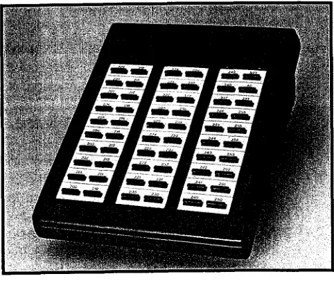
Digital Direct Station Selection Consolet: The
Digital Direct Station Selection (DDSS) con-
sole is an optional, dedicated answering sta-
tion incorporating
a’busy
lainp field (Figure 6),
(
and can only be used with a digital telephone.
It is normally used on systems with a heavy
volume of incoming calls. A DDSS console
may be used with any digital station connected
to the first circuit on the digital telephone inter-
face PCB (PDKU). Up to four DDSS consoles
can be supported with a PCTU3 PCB.
0
0
0
DDSS consoles are equipped with auto-
matic line hold, and voice or tone signaling
capability. The consoles have 60 flexible
buttons, each with an associated LED (the
DDSS button LEDs will light red or green
depending on the button function). Each
flexible button can be assigned one of the
following functions:
All call page (pre-assigned)
CO line appearance
Direct station selection with busy LED
Night transfer (pre-assigned tenant 1 or
tenant 2, if necessary)
Speed dial
Each DDSS console requires one station
port on a PDKU, always the eighth circuit.
A DDSS console must be assigned to a
particular station when the system configu-
ration is defined in programming. All four
DDSS consoles can be assigned to one
station, or four different DDSS consoles
may be assigned to four different stations
(or any intermediate combination). The
same DDSS console may not be assigned
to more than one station.
FIGURE 6- DIGITAL DIRECT STATION
SELECTION CONSOLE
Electronic Telephones
- Four different models of 6500-series electronic
telephones are available. The phones are en-
closed in a stylish, impact-resistant case (either
ash white or charcoal gray) with a matte finish,
and blend easily into any progressive office envi-
ronment. Toshiba electronic telephones that are
compatible with the analog STRATA/STRATA,
key telephone systems are also compatible with
the STRATA DK systems. However, some fea-
tures may vary (e.g. LCD and busy lamp field
telephones).
All 6500-series electronic telephones and DSS
consoles have the same dimensions:
Height: 3.6 in (92 mm)
Width: 7.0 in (178 mm)
Length: 9.0 in (229 mm)
In standard form all electronic telephones may
be wall mounted without additional equipment,
and they are also hearing aid compatible.
Each electronic telephone also features a
standard modular handset cord, and is connect-
ed to the system with a 2-pair modular line cord.
Various upgrade options, such as the off-hook
call announce and loud ringing bell upgrade
assemblies, require special wiring. A 3-pair mod-
ular line cord is required for off-hook call
announce, and a custom external speaker cable
is required for the loud ringing bell.
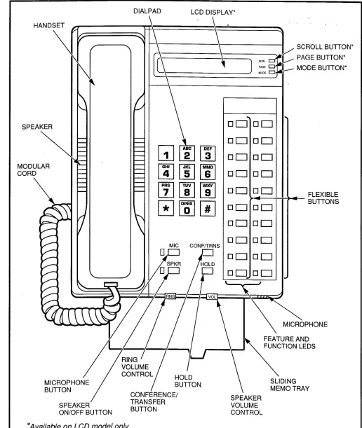
lo-button
Electronic
Telephone (Figure 7):
The 6510 model is available in two variations;
as a speakerphone or with handsfree answer-
back capability on intercom lines.
20-button Electronic
Telephone (Figure 8):
The 6520 model is available with handsfree
answerback capability on intercom lines.
20-button Liquid Crystal Display Electronic
Telephone (Figure 9): The 6520SD is avail-
able only as a speakerphone with a 32-char-
acter, alphanumeric
liquid crystal display
(LCD) field. The numerous LCD features
include:
l
Alphanumeric Messaging
STRATA DK
GENERAL DESCRIPTION
DECEMBER 1990
”
FIGURE 7-IO-button ELECTRONIC TELEPHONE
FIGURE 8-20-button ELECTRONIC TELEPHONE
l
Called Station Messaging
lCalling Station Messaging
lBusy Station Messagingt
l
Group/Remote Station Messaging-t
lBusy Lamp Field (BLF) Indication
lCO Line Identification
l
Speed Dial Memo
l
Timed Reminders with Messages
lIntercom User Name/Number Display
lCall Duration Display
System software allows the customer to
assign feature buttons on all electronic tele-
phones in a completely flexible manner.
j-Requires Release 3 software
-8-
FIGURE 9-20-button LIQUID CRYSTAL DISPLAY
ELECTRONIC TELEPHONE
Electronic
Telephone Upgrade Options: All
electronic telephones may be upgraded with
off-hook call announce, loud ringing bell, and
headset capability.
l
Off-hook Call Announce Upgrade: Each
electronic telephone may be upgraded to
receive intercom calls when the handset is
off-hook by installing an off-hook call
announce upgrade assembly.
l
The assembly consists of two PCBs,
HVSU and HVSI, which install inside the
telephone base with plug-in connectors.
l
Only those telephones programmed to
receive OCA announcements require
the OCA upgrade.
l
Each station PCB (PEKU or PESU) that
supports electronic telephones with
OCA capability must be equipped with
an EOCU subassembly.
l
Loud Ringing Bell/Headset
Upgrade:
Each electronic telephone may also be
upgraded to provide a loud ringing bell
interface and a modular headset interface.
To accomplish this, an upgrade assembly
consisting of a small PCB (HHEU) installs
inside the phone with a plug-in connector.
l
An external speaker (HESB) can be
the phone’s ring. On voice first intercom
calls, the HESB amplifies the caller’s
voice announcement. See the External
Speaker option.
l
Most standard headsets plug into the
HHEU jack and are compatible with the
electronic telephone.
l
An electronic telephone may use all avail-
able upgrade options simultaneously. For
example, the same station may be upgrad-
ed with a DSS console, OCA, a loud ring-
ing bell, and a headset.
Direct Station Selection Console: The Direct
Station Selection (DSS) console is an optional,
dedicated answering station incorporating a
busy lamp field (Figure 10). It is normally used
on systems with a heavy volume of incoming
calls. A DSS console may be used with any
station connected to the first circuit on a PEKU
PCB. Up to four DSS consoles can be sup-
ported with a PCTU PCB, and up to three with
a PCTUS PCB.
DSS consoles are equipped with automatic
line hold, and voice or tone signaling capa-
bility. The consoles have 60 flexible but-
tons, each with an associated LED. Each
flexible button can be assigned one of the
following functions:
l
All call page (pre-assigned)
0 CO line appearance
l
Direct station selection with busy LED
lNight transfer (pre-assigned tenant 1 or
tenant 2, if necessary)
l
Speed dial
Each DSS console requires two station
ports (circuits 7 and 8) on an electronic
telephone interface PCB (PEKU). Only one
DSS console may be installed on a partic-
ular PEKU.
A D$S console must be assigned to a par-
ticular station when the system configura-
tion is defined in programming. All four
DSS consoles can be assigned to one sta-
tion, or four different DSS consoles may be
assigned to four different stations (or any
intermediate combination). The same DSS
console may not be assigned to more than
one station.
FIGURE10
DIRECTSTATIONSELECTIONCONSOLE
Toshiba Peripherals
This section describes each peripheral item
that is available from Toshiba. Configuration and
connection considerations are noted when appli-
cable. For more detail regarding PCB interfaces,
see Printed Circuit Boards.
Stand-alone Data Interface Unit (PDIU-DS)t:
The PDIU-DS (Figure 11) is used for making
switched data connections for modem pooling,
printer sharing, and host/mainframe computer
accessing. LEDs on the front panel indicate
transmission status. Each PDIU-DS requires
FlGUREll-STAND-ALONEOATAINTERFACE
UNlT(PDIU-OS)
t Requires Release 3 software
STRATA DK
GENERAL DESCRIPTION
DECEMBER 1990
TABLED
DATA INTERFACE SPECIFICATIONS
=
ITEM SPECIFICATIONS
Terminal Interface Specification RS-232C (EIA)
V.24/V.28 (CCITT)
Data Transmission Speed
Flow Control
Automatic Dialing
Up to 19.2kbps, asynchronous
Half and full duplex, utilizing RTS/CTS/CD control leads
Based on AT commands:
l Data speed of AT command is 300,600,
1200,2400,4800, or 9600
l Data bit: 7 or 8 bits
l Stop bit: 1 or 2 bits
. Parity bit: even, odd, or no parity
Maximum Distance: KSU to DKTAMJ or DIU stand-alone
l With local power; 1000 feet with 1 -pair (24 AWG)
l With battery back-up: 330 feet with 1 -pair or 1000 feet
with 2-pair (24 AWG)
Number of Wire Pairs 1 -pair or 2-pair (24 AWG)
POWER: Lights when power is on
LED Indicators (stand-alone DIU only) READY: Lights when DTE and DIU are ready
CONNECT: Lights when DIU is in transmission or ringing mode
Automatic Disconnect Timeout signal on SD or RD within nine minutes Forced hang up when DIU does not detect space
LSI Technology
l One-chip CPU with a clock frequency of 12.288MHz
l Memory: ROM, 16KB; RAM, 512kb
l Ping-pong transmission: LSI with bearer transmission rate of
512kbps, 2B+D-type link
STRATA DK Option Compatibility
Digital telephones with integrated DIU:
l No HHEU (headset/loud ringing bell)
l No wall mount
l No DVSU (off-hook call announce)
l Compatible with associated digital DSS console
l DIU to DTE/DCE device: 8-wires,
Cabling/Connectors
50 feet maximum, 24 AWG: compatible with RJ-45, 8-wire modular cable and RJ-45 to DB25 RS-232 modular adaptors
l Stand-alone DIU: RJll modular connector
l Integrated DIU: connected inside digital telephone
l Stand-alone DIU jumper plugs enable straight wire connection
to a DTE or DCE device without null-modem cables or adapton
one 2B+D station port on a PDKU (see Printed
Circuit Boards) and will function on one wire
NOTES:
1. The PDIU-DS will function with all slots,
except slots 11 u 14 in DK96.
2. Modems, printers, and mainframes are
connected
to the standard RS-232
DB25 connector on the PDIU-DS (see
Table 0).
Door Phone: In one of its most popular applica-
tions, the door phone (Figure 12) mounts out-
side a building, next to a locked door whose
entry requires screening. An individual located
outside the building who wants to speak with
someone inside simply presses the button on
the door phone. A distinctive tone will then
sound over the speakers of the digital and/or
electronic telephones defined to do so through
system programming. Any digital or electronic
telephone user can answer and converse with
the individual at the door phone. If the system
is properly configured, the user can allow entry
using a door lock button on the digital or elec-
tronic telephone.
l
A door phone also functions as a sound
monitor. Any telephone can call the door
phone and listen to sounds within its
immediate area.
l
Up to twelve door phones can be support-
FlGURE12-DOORPHONE
ed with a PCTU, up to nine with a PCTUS.
A
door
phone/lock
control
unit
-
(HDCB-Figure
13) must be installed to
support up to three door phones (or two
door phones and one door lock control).
Each HDCB requires one station port on
an electronic telephone interface PCB
(PEKU or PESU). Only one HDCB can be
installed on a particular PEKU or PESU.
FlGURE13-DOORPHONE/LOCK
CONTROLUNlT(HDCB)
NOTE:
The PDKU cannot support an HDCB.
l
Door lock control requires an optional
interface PCB (PIOU, PEPU, or PIOUS)
and/or an HDCB. Up to five door lock con-
trols can be installed, but each door lock
controlled by an HDCB reduces the door
phone capacity on that HDCB from three
to two.
External Speaker: The HESB external speaker
unit is a 6-inch, 3-watt speaker with a built-in
amplifier (Figure 14). A +12 VDC power supply
(HACU-120) is included with each external
speaker. It connects to the back panel with an
8-foot cord and plugs into a 117VAC, 60 Hz
outlet. The HESB has three applications:
l
Amplified
Paging Speaker: Allows the
HESB to be used as a paging speaker,
reducing the need for other manufacturers’
paging equipment.
-ll-
STRATADK
GENERALDESCRIPTION
DECEMBER1990
FlGURE14-EXTERNALSPEAKER(HESB)
l Amplified Talkback Speaker: When used
in conjunction with external page, an
HESB can be installed as a talkback
device. The HESB is connected to the
door phone, which is used as a micro-
phone to provide talkback capability.
l Loud Ringing Bell: Allows the voice/tone
of a paging/ringing call to any digital tele-
phone or 6500-series electronic tele-
phone to be amplified. When an HESB is
connected as a loud ringing bell, an
HHEU upgrade assembly must be
installed in the digital or electronic tele-
phone’s base. See the loud ringing
bell/headset telephone upgrade in the last
section. An external speaker cable
(HESC-65 for electronic telephones;
HESC-65A for digital telephones) con-
nects the station to the speaker.
TABLEE
STATION LOOPREQUIREMENTS
Device Description Max Loop Resistance (Including Device) Max Distance from KSU to Device Number of Wire Pairs’
PEKU
(ckts 1 - 8) telephone, Electronic
400hms iOOOft.(303m) All need 2-pair.
PLJ’ door phone/
EKTs which
control boxes receive OCA
(ckts 5 w 8) calls need
PEKU 3-pair!
(ckts 7 & 8) DSS consoles 200hms 500ft.(152 m)
PSTU Standard Approx. 3000 ft. (909 m)
(ckts 1 m 8) telephones, with 150 ohm device. See
P&J 2
voice mail, 3000hms manufacturer’s product 1 -pair
auto attendant, specifications for exact
(ckts 1 & 2) etc. resistance of device.
PDKU Digital
(ckts 1 w 8) telephones 400hms lOOOfL(303m) 1 -pair
PDKU
(ckt 8) DDSS consoles 200hms lOOOfL(303m) 1 -pair
PDKU Shares digital
(ckts 1 m 8) PDIU-DI 400hms lOOOfL(303m) telephone wire-pair?
PDKU
(ckts 1 * 8) PDIU-DS 400hms lOOOfL(303m) 1 -pair3
NOTES:
1. Use 24 A WG twisted pairs.
2. PESU circuits 3 and 4 are not used.
I
3. Two-pair or larger wire is required to achieve maximum range.
TABLE
F
NETWORK
REQUIREMENTS
PCB Interface Code Facility Network Jack Equivalence Ringer
PCOU
(Loop start line)
02LS2
RJ14C
0.2B
PEMU
(Type I, TIE line)
2-wire
TLllM
RJ2EX
N/A
4-wire
TL31 M
RJ2GX
N/A
PESU/PSTU
(Off-premises station)
OL13A
RJ21 X
N/A
(see note)
NOTE:
On PEW, circuits I and 2 only provide off-premises capability.
Power Failure Transfer Unit: An optional exter-
nal power failure transfer unit (DPFT) may be
connected to the system with a PSTU PCB to
provide emergency service in the event of a
power failure.
Up to eight CO lines are
switched directly to dedicated conventional
telephones (customer-provided 2500- or 500-
type) for incoming and outgoing calls. When
power is restored, stations/CO lines reserved
for power failure transfer will automatically
return to normal service. Standard telephones
that are connected to the PESU PCB can also
be connected to the DPFT to provide emer-
gency service.
Customer-supplied
Peripherals
All three STRATA DK digital key systems sup-
port many other commonly used peripheral
devices which can be supplied by the customer.
Several of these devices are listed below (with
the supporting PCB or data interface unit noted):
l
Auto attendant device (PSTU or PESU)
lDictation equipment (PSTU or PESU)
l
External maintenance
modem (PIOU or
PIOUS)
l
Facsimile (PSTU or PESU)
0 Local maintenance terminal (PIOU or PIOUS)
l
Modem (PSTU, PESU, or PDIU-DS)t
l
Paging system (PIOU, PIOUS, or PEPU)
lRadio paging equipment (PSTU or PESU)
lRemote maintenance terminal (PIOU or
PIOUS with IMDU)
l
Standard telephones (PSTU or PESU)
l
SMDR printer/call accounting device (PIOU
or PIOUS)
l
Voice mail messaging system (PSTU or
PESU)
l
Printers (PDIU-DS)t
l
Personal Computers (PDIU-Dl)t
l
Mainframe Computer Access (PDIU-DS)t
3 SYSTEM HARDWARE DESCRIPTION
Key Service Units
Key Service Unit Exterior: All three systems
can be mounted on a wall or table top. The
basic key service unit consists of a single
metal cabinet (Figure 2) with the following
dimensions. Weight measurements approxi-
mate fully loaded systems.
STRATA DK24
Height: 10.6 in (269 mm)
Width: 16.0 in (406 mm)
Depth: 9.1 in (230 mm)
Weight: 194 Ibs (9 kg)
t Requires Release 3 software
STRATA DK
GENERAL DESCRIPTION
DECEMBER 1990
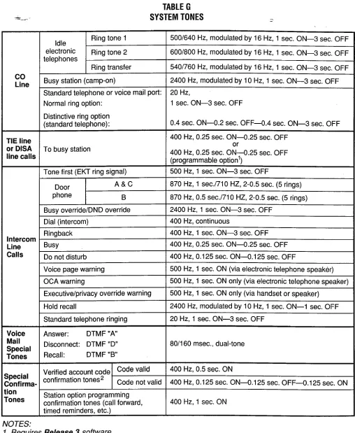
TABLE G
SYSTEM TONES
-.
Idle Ring tone 1 5001640 Hz, modulated by 16 Hz, 1 sec. ON-3 sec. OFF
electronic
telephones Ring tone 2 600/800 Hz, modulated by 16 Hz, 1 sec. ON-3 sec. OFF
Ring transfer 540/760 Hz, modulated by 16 Hz, 1 sec. ON-3 sec. OFF
co
Line Busy station (camp-on) 2400 Hz, modulated by IO Hz, 1 sec. ON-3 sec. OFF
Standard telephone or VOiCf? mail port: 20 Hz,
Normal ring option: 1 sec. ON-3 sec. OFF
Distinctive ring option
(standard telephone): 0.4 sec. ON-O.2 sec. OFF-O.4 sec. ON-3 sec. OFF
TIE line 400 Hz, 0.25 sec. ON-O.25 sec. OFF
or DISA To busy station or
line calls 400 (programmable Hz, 0.25 sec. ON-O.25 option’) sec. OFF
Tone first (EKT ring signal) 500 Hz, 1 sec. ON-3 sec. OFF
Door A&C 870 Hz, 1 sec.1710 HZ, 2-0.5 sec. (5 rings)
phone B 870 Hz, 0.5 sec./71 0 HZ, 2-0.5 sec. (5 rings)
Busy override/DND override 2400 Hz, 1 sec. ON-3 sec. OFF
Dial (intercom) 400 Hz, continuous
Ringback 400 Hz, 1 sec. ON-3 sec. OFF
Intercom
Line Busy 400 Hz, 0.25 sec. ON-O.25 sec. OFF
Calls Do not disturb 400 Hz, 0.125 sec. ON-O.125 sec. OFF
Voice page warning 500 Hz, 1 sec. ON (via electronic telephone speaker)
OCA warning 500 Hz, 1 sec. ON only (via electronic telephone speaker)
Executive/privacy override warning 500 Hz, 1 sec. ON only (via handset or speaker)
Hold recall 2400 Hz, modulated by 10 Hz, 1 sec. ON-l sec. OFF
Standard telephone ringing 20 Hz, 1 sec. ON-3 sec. OFF
Voice Answer: DTMF “A”
Special Disconnect: DTMF “D” 80/l 60 msec., dual-tone
Tones Recall: DTMF “B”
Verified account code ‘Ode valid 400 Hz, 0.5 sec. ON
Special
Zonfirma- confirmation tones2 Code not valid 400 Hz, 0.125 sec. ON-O.1 25 sec. OFF-O.125 sec. ON
[ion
rones Station option programming confirmation tones (call forward, 400 Hz, 1 sec. ON
timed reminders, etc.)
NOTES:
1. Requires
Release 3software.
2.
Tones are sent only to the station that enters the
not to the outside party.
STRATA DK56
Height: 15.0 in (380 mm)
Width: 16.1 in (410 mm)
Depth: 9.1 in (230 mm)
Weight: 37.5 Ibs (17 kg)
STRATA DK96
Height: 18.7 in (475 mm)
Width: 19.7 in (500 mm)
Depth: 9.1 in (230 mm)
Weight: 55.1 Ibs (25 kg)
Key Service Unit Interiors:
l
The DK24 cabinet interior (Figure 15) has
one shelf with seven PCB slots, labeled
PCTU, SO1 w S06. The power supply is
positioned vertically on the right side of the
shelf, and is installed at the factory.
l
The DK56 cabinet interior (Figure 16) has
one shelf with nine PCB slots, labeled
PCTU, SO1 w S08. The power supply is
positioned horizontally above the shelf,
and is installed at the factory.
l
The DK96 cabinet interior (Figure 17) has
two shelves. The top shelf has eight PCB
slots, labeled SO1 N S08; the bottom has
seven PCB slots, labeled PCTU, SO9 N
S14. The power supply is positioned ver-
tically to the right of the shelves, and is
installed at the factory.
System Printed Circuit Board Slots: Each
system is equipped with universal PCB slots
that are extremely flexible and can be config-
ured to suit individual customer needs. All
station, CO line and optional PCBs are the
same size, and use the same connector type
to mount into the cabinet’s backplane.
Therefore, any PCB can be installed in any
universal slot, with the exception of the PCTU
or PCTUS, which must be installed in the slot
labeled PCTU.
System Operation
A system consists of a key service unit and
up to either 32 stations in DK24, 56 stations in
DK56, and 96 stations in DK96 (station loop
b
FIGURE 15-DK24 CABINET INTERIOR
-15-
STRATADK
GENERALDESCRIPTION
DECEMBER1990
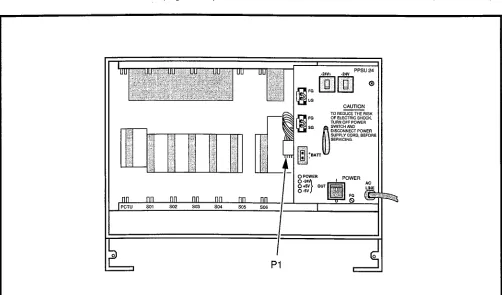
Pl
FlGURE16-DK56 CABINET INTERIOR
FlGURE17-DK96 CABINETINTERIOR
f
lengths, network requirements, and system tone
patterns are summarized in Tables E, F, and G,
respectively).
The system can have several options config-
ured, as illustrated in the functional block dia-
gram (Figures 18A and 18B).
As represented in the functional block dia-
gram, the system’s cabinet contains a power
supply and printed circuit boards appropriate to
the user’s configuration. PCBs include the com-
mon control unit (PCTU2, PCTU3, or PCTUS),
DTMF receiver subassembly (CRCU-4 or CRCU-
8), option interface unit (PIOU, PIOUS, or
PEPU), remote maintenance modem subassem-
bly (IMDU), CO line unit (PCOU), E & M TIE line
unit (PEMU), digital telephone interface unit
(PDKU)t, electronic telephone interface unit
(PEKU), off-hook call announce subassembly
(EOCU), standard telephone interface unit
(PSTU), and a combination electronic/standard
telephone interface unit (PESU).
!iD
Printed Circuit Boards
Most STRATA DK system hardware options
are integrated within the system cabinet. Each
major PCB measures 7.5 x 5.5 inches (190 x 140
mm) and mounts in a PCB slot in the shelf with a
44-pin backplane connector.
PCB external connections are made to the
Main Distribution Frame (MDF) using the follow-
ing industry-standard connectors:
l
25pair Amphenol Female: Connects digital
telephones, electronic telephones, standard
telephones, and most peripherals.
l
Modular: Connects CO lines, E & M TIE
lines, station message detail recording port
(W-232), and maintenance port (RS-232).
l
Terminals: MOH and some peripherals.
The following list includes every PCB that can
be installed in the key service unit. Each PCB’s
function is described, along with applicable con-
figuration and connection details.
Common Control Unit (PCTU): The PCTU is
the system’s controller PCB, and must be
installed for the system to operate. It contains
the system’s main 16-bit, 68000-type micro-
-processor and microprocessor bus, battery-
protected memory circuits, time switch logic,
conference logic, and system tones. The
PCTU also has a music-on-hold/background
music source interface, and connectors to
mount an optional
DTMF receiver PCB
(CRCU) for DISA, TIE lines, standard tele-
phones and peripherals. There are three ver-
sions of PCTU PCBs available:
PCTUS,
PCTU2, and PCTU3. PCTUS and PCTU2 pro-
vide Release 2 features; PCTU3 provides
Releases 2 and 3 features. See Table H for
PCTU comparison and compatibility.
DTMF Receiver Subassembly
(CRCU): An
optional DTMF receiver PCB mounts onto the
PCTU piggy-back style. It translates DTMF
signals from direct inward system access
(DISA) CO lines, TIE lines, standard tele-
phones or peripheral devices to data signals
for the system.
l
One CRCU option must be installed for the
system to receive DTMF dialing. Both 4-
and 8-circuit CRCUs are available (CRCU-
4 and CRCU-8).
l
CRCU DTMF receiver circuits are shared
by users, i.e. a receiver is seized for dial-
ing and then released for the next call.
Option Interface Unit (PIOU): The PIOU pro-
vides a circuit interface with the peripheral
options, including external paging functions,
alarm interface, SMDR, and remote mainte-
nance. Table I shows details of each feature.
Simplified
Option Interface Unit (PIOUS): A
reduced model of the PIOU, the PIOUS pro-
vides an interface with the peripheral options
shown in Table I.
External Page Interface Unit (PEPU): Also a
reduced model of the PIOU, the PEPU pro-
vides a circuit interface with the peripheral
options shown in Table I.
Remote Maintenance fvlodem’ Subassembly
(IMDU): An optional built-in modem provides
the system with a link to off-site programming
STRATA DK
GENERAL DESCRIPTION
DECEMBER 1990
z4. DKSU 24/56/96
-
PCOU
LINE P-PAIR
~ _ MODCORD LOOP START LINE PCB (4 CIRCUITS)
LINE ‘2-PAIR 1 AND2 MODULAR P-PAIR ’ - JACK ~ _ MODCORD 1 *
I I MODULAR ’ - LOOP START LINES
* FIC: 02LS2 . USOC: RJI 4C . REN: 0.2B
I I
i id 4 E&ML4t
bW klL%
I I I I I 1 *I TIE-LINE ~~ l-z-l I I
E&M TIE LINES I I I I 3 PCB 31 ,“,:: I l-l+ . FIC:
2-W; TLI 1 M 4-W: TL31 M
usoc:
2-W; RJPEX 4-W; RJPGX
S-PAIR MOD CORD
I
‘3-PAIR
1 MODULAR 1 JACK
cl i% MDF
!MlNG TERMINAL OR MODEM
CALL ACCOUNTING DEVICE f!-fj opTlo;~N~~;C~~y 1
MAIN DISTF FRAME MC
I&
.
REN: NIA
I
25PAIR AMPHENOL (PlOU/PEPU) ORSPRING TERMINAL STRIP I AMPLIFIED PAGE OUTPUT
MUSIC SOURCE: EXTERNAL ZC BACKGROUND MUSIC
I
DOOR LOCK OR BGM MUTE CONTROL RELA\I
MAIN PCTU
CONTROL PCB (SEE TABLE B) TWISTED PAIR ’
NIGHT BELL OR MOH (CONTROL RELAY)
ALARM RELAY SENSOR
1
EXTERNAL ZONE PAGE RELAYS (4 ZONES)
EXTERNAL PAGE AMPLIFIER
-1 II RECEIVER II I
MUSIC SOURCE: BACKGROUND AND/OR -
I
I
MUSIC-ON-HOLD , - I \
TWISTED PAIR MOHlBGM VOLUME CONTROL
FIGURE 18A-DK FUNCTIONAL BLOCK DIAGRAM
MI-IF HESB
t ---
- - - - E!%J 24/56/96 jl$:,“:::::r,:,
l”lYl
__-w--v, - --
k
-LOUD’ .I
. .
8 z
BGM SOURCE TO STATIONS 2- (
tbi i r
tttt
$F;;;;;;;pD DOOR PHONES AND LOCK CONTROLS
PSTU (8 STD CIRCUITS)
or .
PESU (ZSTDC(.CUTS)( STANDARD TELEPHONE
(NOTE 1)
POWER FAILURE , -&‘(PSTU ONLY) TRANSFER UNIT
(8 DIGITAL CIRCUITS) (8 DIGITAL CIRCUITS) DIGITAL ELECTRONIC TELEPHONE/ DIGITAL ELECTRONIC TELEPHONE/ DIU STATION PCB
DIU STATION PCB
PDKU”
25.PAIR AMPHENOL (FEMALE)
1 I I I
n I
1 1 CABLES .Li
125-PAIR ‘CABLE - !
- 1
-.-....-
TELEPHONE3
PPSU
MODULAR CORDS
I NOTES:
117VAC (15 AMP) m/fin H7
Can be on-premises or off-premises (OPS: FC = OL13A; USOC = RJ2X)
7 external devices connected to the PCTU, 2. Al,
PFS// P1
I LVV, , I ‘OU, PSTU, PEMU, and PCOU must be industry-standard and supplied by the customer. All devices connected to the PDKU and PEKU are Toshiba proprietary.
Requires Release 3.
- PBTC CABLE
.IED
FlGURE18B-DKFUNCTIONALBLOCKDIAGRAM
-19-
STRATA
DK
GENERAL
DESCRIPTION
DECEMBER
1990
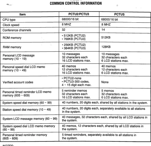
TABLE
H
COMMON
CONTROL
INFORMATION
_
Item PCTU2/PCTU3
CPU type 68000/i 6 bit
Clock speed 8 MHZ
Conference channels 32
PCTUS 68000/i 6 bit
8 MHZ 14
ROM memory
RAM memory
Personal LCD message memory (10 w 19)
Personal speed dial LCD memo memory (10 m 49)
Verified account codes
l 512KB (PCTU2)
l 768KB (PCTU3)
l 256KB (PCTU2)
l 384KB (PCTU3)
10 messages 32 characters each 16 LCD stations max.
512KB
128KB
10 messages 32 characters each 6 LCD stations max.
40 memos
12 characters each 16 LCD stations max.
l PCTU2-none
l PCTU3-300 codes,
4 w 15 digit each max.
40 memos
12 characters each 6 LCD stations max.
None
Personal timed reminder LCD memo memory (605 w 609)
5 reminder memos 32 characters each 16 LCD stations max.
5 memos
32 characters each 6 LCD stations max.
System speed dial memory (60 m 99) 1 40 numbers, 20 digits each, shared by all stations in the system.
Station speed dial memory (10 N 49) 40 numbers, 20 digits each, separately available to all stations
in the system.
System LCD message memory (60 m 99) the system 40 messages, 32 characters each, shared by all LCD stations in
System speed dial LCD memo memory (60 - 99)
Personal timed reminder memory (605 - 609)
40 memos, 12 characters each, shared by all LCD stations in the system.
5 timed reminders, separately available to all stations in the system.
NOTES:
1. The PCTUS is compatible with DK24 only; however, the PCTU may be used with all systems.
2. The PCTU and PCTUS provide MOH/BGM interface with volume control and support either CRCU-4 or -8.
3. See Tables J and K for PCTU and PCTUS configuration information.
4. PCTU2, PCTU3, and PCTUS ROMs are not interchangeable.
NOTE:
X = the option is provided.
and maintenance equipment, such as a per-
sonal computer or ASCII terminal. The IMDU
has an internal maintenance channel and
does not require a dedicated CO line or station
port. Data transmission speed can be set at
300 or 1200 BPS full duplex.
l
The IMDU mounts on top of the option
interface unit (PIOU or PIOUS) piggy-back
style.
TABLEI
OPTIONALINTERFACE-PCB OPTIONS
Interface Option
PIOU
Unamplified page output (single zone, 600 ohms, duplex) X
Amplified page output (single zone, 3 watts, 8 ohms) X
Zone page interface (unamplified, 4 zones) X
Night transfer or music-on-hold control relay X
Door lock or external amplifier control relay X
PIOUS
X
X
X
PEPU
X
X
X
X
I
I I I I
Alarm sensor
SMDR output (RS-232/6-wire modular connector)
Maintenance port for a local ASCII terminal or external
modem (RS-232/6-wire modular connector)
Remote maintenance modem (IMDU subassembly, no
external connector)
X X
X X
X X
X X
CO Line Unit (PCOU): The PCOU provides the
system with four loop-start CO lines and a
standard, built-in automatic busy redial (ABR)
circuit.
Each CO line can be programmed to
be either DTMF or dial pulse. In addition, each
CO line has a 3 dB pad option switch to con-
trol excessive loudness resulting from close
proximity
to the PBX or central office. Each
CO line circuit provides built-in gas tubes for
limited protection from lightning.
l
A maximum of four PCOU PCBs can be
installed in
DK24
to provide sixteen COlines, five
PCOU PCBs can be
installed inDK56 to provide twenty CO lines, and nine in
DK96 to provide thirty-six CO lines.
l
Connections from the PCOU to the MDF
are made with modular connectors, each
with two circuits.
E 81 M TIE Line Unit (PEMU): The PEMU pro-
vides for E & M Type I signaling, immediate-
start TIE lines. Each PEMU reduces the maxi-
mum system capacity by four CO lines and
four stations (four CO lines and eight stations
if the PCTUS is used). A choice between 2- or
4-wire transmission is available as a jumper-
plug option.
l
A maximum of one PEMU can be installed
in DK24 to provide four TIE lines, two in
DK56 to provide eight TIE lines, and three
in DK96 to provide twelve TIE lines (see
Table K for details).
l
Connections from the PEMU to the MDF
are made with modular connectors, each
with one circuit.
Digital Telephone Interface Unit (PDKU)t: The
PDKU provides eight
ports for digital tele-phones and data interface units (PDIU-DI
andPDIU-DS). It can support one DDSS console.
PDKUs supporting digital telephones with off-
hook call announce do not require an EOCU.
t Requires Release 3 software