Vol. 3, Issue 12, December 2014
Design and Implementation of Inverted
U-Shaped Slot Loaded Proximity Coupled
Equilateral Triangular Microstrip Antenna
for Triple Band Operation
Mahesh
C. P
1, P. M. Hadalgi
2Research Scholar, Department of P.G. Studies and Research in Applied Electronics, Gulbarga University,
Gulbarga, Karnataka, India1
Professor, Department of P.G. Studies and Research in Applied Electronics, Gulbarga University,
Gulbarga, Karnataka, India2
ABSTRACT:This paper presents the design and development of proximity coupled equilateral triangular microstrip antenna using inverted U- shaped slot loading for triple band operation. The antenna operates between 2.75 GHz to 8.38 GHz range. The antenna gives a maximum impedance bandwidth of 6.50%. The substrate used for design of antenna is glass epoxy material (∈r =4.2). The microstripline feed arrangement is incorporated to excite the antenna. The proposed antenna shows broadside radiation characteristics. The design of the antenna is described. The simulated results are presented and discussed. These antennas are useful for the applications such as WIFI (wireless fidelity), IMT (International mobile telecommunication) and in radar.
KEYWORDS: Inverted U-shaped, Proximity coupled, Equilateral Triangular, radiation patterns, return loss, VSWR.
I.INTRODUCTION
Antennas play a very important role in the field of wireless communications. Some of them are Parabolic Reflectors, Patch Antennas, Slot Antennas, and Folded Dipole Antennas. Each type of antenna is good in theirown properties and usage. We can say antennas are the backbone and almost everything in the wireless communication without which the world could have not reached at this age of technology. Patch antennas plays a very significant role in today’s world of wireless communication systems. A microstrip patch antenna [1] is very simple in the construction using a conventional microstrip patch antenna fabrication technique. The most commonly used microstrip patch antennas are rectangular, square, ellipse, circular etc., patch antennas. The equilateral triangular radiating patch antennas are used as simple and for the widest and most demanding applications [2].
II. ANTENNA DESIGN CONSIDERATION
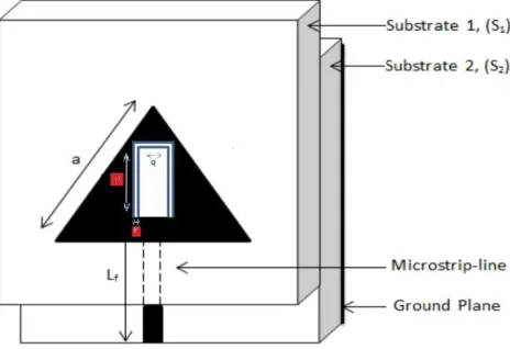
In this article the proposed antenna has been designed for the frequency of 3 GHz using the relations present in the literature for the design of equilateral triangular microstrip antenna. The simple commercially available glass epoxy substrate material with substrate S1 and S2 having thickness of 0.32 cm is used to simulate the antenna. The Fig. 1
shows the top view geometry of inverted U-shaped slot loaded proximity coupled equilateral triangular microstrip antenna (IUSPCETMSA) and Ansoft HFSS simulated antenna module of IUSPCETMSA as shown in Fig. 2.
Fig. 1 Top view geometry of IUSPCETMSA
Fig. 2 Simulation antenna module of IUSPCETMSA
The equilateral triangular radiating patch with inverted U-shaped slot loaded on top surface of substrate S1, where p, q
and r are the dimensions of the U-shaped slot respectively. The microstripline feed of Lf and Wf is etched on the top
surface of substrate S2. The glass epoxy substrate material S2 is placed below substrate S1 such that the tip of the feed
line and the center of the radiating patch consider one over the other. Here the bottom surface of the substrate S2 acts as
the ground plane. The dimensions of the ground plane Lg and Wg are calculated from equation (1). All the specifications of the proposed antenna are given in Table. 1.
Vol. 3, Issue 12, December 2014
Table 1: Simulated parameters of the proposed antennas
Antenna Parameters Dimensions in cm
Side length of equilateral triangle (a) 2.70
Width of the feedline Wf 0.63
length of the feedline Lf 2.5 Width and Length of the ground plane
(Wg and Lg) 4.6
Thickness of substrate S1 and S2 0.64
p 1.5
q 0.4
r 0.1
III. SIMULATION RESULTS AND DISCUSSION
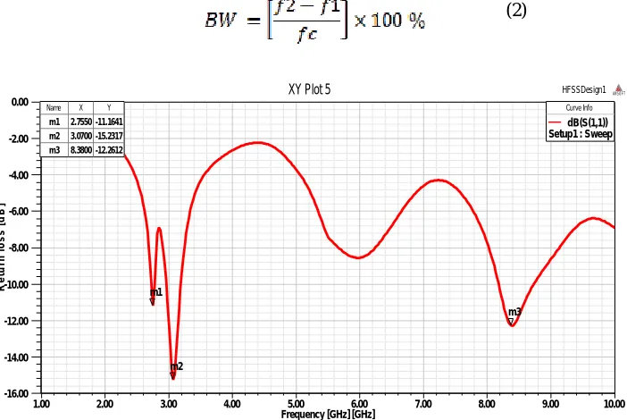
The characteristics of proposed IUSPCETMSA is designed and simulated by using Ansoft HFSS simulation software. The variation of return loss versus frequency characteristics of IUSPCETMSA antenna as shown in Fig.3. From this graph it is seen that, the antenna resonates very close to its designed frequency of 3GHz. The impedance bandwidth over return loss less than -10dB is calculated by using the equation (2).
(2)
1.00 2.00 3.00 4.00 5.00 6.00 7.00 8.00 9.00 10.00
Frequency [GHz] [GHz] -16.00
-14.00 -12.00 -10.00 -8.00 -6.00 -4.00 -2.00 0.00
R
e
tu
rn
l
o
s
s
[
d
B
]
HFSSDesign1
XY Plot 5 ANSOFT
m1
m2
m3 Name X Y
m1 2.7550 -11.1641 m2 3.0700 -15.2317 m3 8.3800 -12.2612
Curve Info dB(S(1,1)) Setup1 : Sweep
Fig.3. Simulation return loss versus frequency of IUSPCETMSA
1.00 2.00 3.00 4.00 5.00 6.00 7.00 8.00 9.00 10.00 Freq [GHz] 0.00 2.00 4.00 6.00 8.00 10.00 12.00 14.00 V S W R (1 ) HFSSDesign1
XY Plot 6 ANSOFT
m1
m2 m3
Curv e Info
VSWR(1) Setup1 : Sweep
Name X Y
m1 2.7550 1.7646 m2 3.0700 1.4188 m3 8.4025 1.6449
Fig.4. Simulation VSWR of IUSPCETMSA
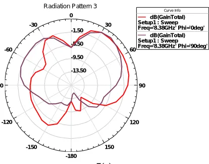
The radiation patterns of the simulated IUSPCETMSA at their resonating frequencies are also studied and plotted. The
E and H plane radiation patterns of the proposed antennas for φ at 00 and is as shown in Fig. 5(a), Fig. 5(b) and Fig.
5(c). This shows radiation patterns are broadside in nature.
-13.20 -10.40 -7.60 -4.80 90 60 30 0 -30 -60 -90 -120 -150 -180 150 120
Radiation Pattern 1
Curve Info
dB(GainTotal) Setup1 : Sweep Freq='2.755GHz' Phi='0deg'
dB(GainTotal) Setup1 : Sweep Freq='2.755GHz' Phi='90deg' 5(a) -15.00 -10.00 -5.00 0.00 90 60 30 0 -30 -60 -90 -120 -150 -180 150 120
Radiation Pattern 2 Curve Inf o
dB(GainTotal) Setup1 : Sweep Freq='3.07GHz' Phi='0deg'
dB(GainTotal) Setup1 : Sweep Freq='3.07GHz' Phi='90deg'
Vol. 3, Issue 12, December 2014
-13.50 -9.50 -5.50 -1.50
90 60 30 0
-30
-60
-90
-120
-150
-180
150 120
Radiation Pattern 3
Curve Info
dB(GainTotal) Setup1 : Sweep Freq='8.38GHz' Phi='0deg'
dB(GainTotal) Setup1 : Sweep Freq='8.38GHz' Phi='90deg'
5(c)
Fig. 5.The simulated radiation patterns of IUSPCETMSA measured at 5(a) 2.75 GHz, 5(b) 3.07GHz, and 5(c) 8.38GHz
VI.CONCLUSION
From the detailed study it is concluded that, the proposed IUSPCETMSA antenna resonates at three frequency points, also gives a highest impedance bandwidth of 6.50%. The radiation patterns of the designed antenna are found to be broadside in nature and linearly polarised at each operating frequencies. This antenna may find applications in WIFI, IMT, radar and other wireless applications.
REFERENCES
1. Wentworth M. Stuart ‘’Fundamentals of Electromagnetics with EngineeringApplications’’, pp 442 445, John Wiley & Sons, NJ, USA, 2005. 2. R. Garg, P. Bartia, I. Bhal, and A. Ittipiboon, Microstrip antenna design handbook, Artech House, Norwood, MA, 2001.
3. HalaElsadek“ Miniaturised Tri-band Equilateral Triangular Microstrip Antennas for Wireless Communication Applications” Microwave and Optical Technology Letters, Vol. 49, No. 2, pp-487-491, February 2007.
4. Sunil Kr singh and Shrirish Kumar Jain “Design of Triangular Microstrip Patch Antenna at Super High Frequency” International Journal of Computer Science and Information Technologies, Vol. 2(5), pp-2288-2289, 2011.