SPECIFIC POWER OPTIMIZATION OF
0.1MWe CLOSED CYCLE OTEC
POWER PLANT
Dr. E. Vijayakrishna Rapaka
Former Assistant Professor, Department of Mechanical Engineering, Pondicherry Engineering College, Puducherry,
India
Abstract: The search for renewable sources of energy resulted in the revival of a concept based on the utilization of the differences in temperature between the warm tropical surface waters and the cold deep ocean water available at depths of about 1000 m as the source of the thermal energy required to vaporize and condense the working fluid of a turbine - generator system respectively. This concept is referred to as “Ocean Thermal Energy Conversion”. As the temperature in the top surface is equal to the ambient temperature and the temperature in the bottom surface is much cooler when compared to the top surface, there exists a temperature difference between the layers of the ocean and this temperature difference is utilized to run an OTEC power plant. In this work, simulation of the OTEC power plant is done to optimize the specific power output by varying the intake velocities and depth. Ammonia is used as the working fluid. The maximum specific power output is obtained for a depth of 600m.
Keywords: Ocean Thermal Energy Conversion, Renewable Energy, Specific Power Output, Salinity
I. INTRODUCTION
Ocean Thermal Energy Conversion (OTEC) utilizes the natural temperature difference between the warm surface water and cold bottom water of the ocean to generate power. Aside from the mediums used to accomplish heat transfer, an OTEC cycle is essentially a Rankine cycle. A basic OTEC cycle requires at least a basic cold water temperature of 20°C which is achieved only through the depths below 500 m or greater. The sunlit and wind-driven upper layer of Earth’s oceans rests on relatively colder and denser waters. At times, there is a distinct temperature difference between the wind-stirred Surface Zone and the quieter Deep Zone below. Although temperature generally decreases with depth, there is a layer where temperatures drop abruptly called the Thermocline region the ocean would stratify into a simple layered structure based on its density. Generally the density increases with increase in salinity.
II. REVIEW OF LITERATURE
G.C. Nilhous et al. [1] have studied the performance of OTEC plant at various depths and height and have proposed that the Overall Heat Transfer coefficient increases at different depths in the experiment carried out at pacific islands. Chih Wu [2] discussed on the specific power optimization for Thermoelectric OTEC plants has concluded that this approach gives more realistic generated specific power and efficiency prediction. Rabas et al. [3] have conducted performance analysis test for different depths and heights for a Hybrid closed cycle with ammonia as the working fluid and have increased the power output to considerable amount. Paul M. Wolff and Lloyd F. Lewis [4] have found that there is a gross resource of energy at the depths of the ocean which help in the increase of the efficiency of the plant. W.H. Avery et al. [5] concluded that OTEC plant ships designed in tropical regions are a potential source of Ammonia, Methanol, and Hydrogen and in great amount could reduce the world dependence on fossil fuels.
A. Specific Power Optimisation:
thermodynamics has been developed in recent years and a literature survey of the finite-time thermodynamics has been reviewed by Chih Wu [2].
B. Finite-Time Rankine OTEC and its Specific Power Optimization.
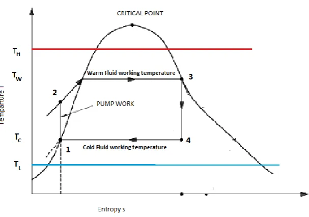
In the finite-time Rankine OTEC heat engine as depicted Fig. 1, the Rankine cycle is made of two isobaric and two isentropic processes. The cycle is considered as a modified Carnot cycle for a liquid – vapour phase change working fluid. The power output of the engine will be zero if it requires an infinite time to get a finite amount of work. In order finite power, the cycle must be speeded up. However, if the heat engine speed is made infinitely fast, the heat would flow directly by the heat engine thereby producing a zero power output which will result in zero heat engine efficiency. It is somewhere between these two extremes, the heat engine will yield a maximum specific power output. The efficiency of the Rankine vapour heat engine under the condition of maximum specific power output is evaluated using the following equations.
Fig. 1 Finite-Time Ranking OTEC Cycle
The rate of heat flow from the high temperature reservoir to the system under consideration for a mean temperature difference (TH-TW) can be calculated as follows.
𝑄𝐻 = 𝑄𝐻∕ 𝑡𝐻= 𝑈𝐻𝐴𝐻(𝑇𝐻− 𝑇𝑊) ... (1)
Where tH is the residence time in the boiler. UH is the overall heat transfer coefficient which includes the heat transfer
by conduction, convection and radiation modes. AH is the surface area of the heat exchanger. TW is the mean effective
temperature of the working fluid during the heat addition. TW can be calculated as follows.
𝑇𝑊= 𝑄𝐻
𝑆3−𝑆1= 𝐻3− 𝐻1+ 𝑊𝑝 /(𝑆3− 𝑆1) ... (2)
Where H is enthalpy; S is entropy and Wp is the pump work required to pump working fluid from the condenser to the
boiler. The rate of heat flow from the system to the low temperature sink for a mean temperature difference (TC-TL) can
be calculated as follows.
𝑄𝐿 = 𝑄𝐿∕ 𝑡𝐿= 𝑈𝐿𝐴𝐿(𝑇𝐶− 𝑇𝐿) ... (3)
Where tL is the residence time in the condensor. UL is the overall heat transfer coefficient which includes the heat
transfer by conduction, convection and radiation modes. AL is the surface area of the heat exchanger.
The total time, t, required for the whole cycle is
𝑡 = 𝑡𝐻+ 𝑡𝐿 ... (4)
𝑃 =𝑊 𝑡 = 1 𝑈𝐻𝐴𝐻 1 (𝑇𝐻−𝑇𝑊) 𝑇𝑊 (𝑇𝑊−𝑇𝐶)+ 1 𝑈𝐿𝐴𝐿 1 (𝑇𝐶−𝑇𝐿) 𝑇𝐶 (𝑇𝑊−𝑇𝐶) −1 (6)
Where, P is the power output of the irreversible heat engine.
The specific power output of the heat engine, p, is defined to be the power output per unit total heat exchangers area, which is given by the following equation
𝑝 = 𝑃
𝐴𝐻+𝐴𝐿= 𝑃
(1+𝑎)𝐴𝐿 ... (7)
Where, a is the ratio of the surface of the boiler to the surface area of the condensor, AH/AL.
III.RESULTS AND DISCUSSION
The specific power output of the 0.1 MWe Closed cycle OTEC Power plant has been simulated for various depth and intake velocity. The overall heat transfer co-efficient and the pressure on the condenser side is also reported.
Fig. 2 Depth versus Specific Power Output
Fig. 2 shows the effect of depth on the specific power output with the variation in the intake velocities. The specific power output decreases with increase in the depth. The main factor that affects the specific power output is the heat exchanger area. The experimental data indicates that, the cold water pipelines would involve length of 2040, 2470 and 3080 m to the depths 620, 820, 1100 m. Since the specific power output is the ratio of the heat transferred to the heat exchanger area, the specific power output decreases as the area increases. The Specific power Output is found to be maximum at a depth of about 600m.
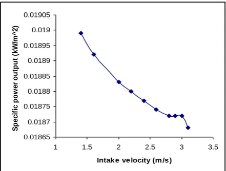
Fig. 3 Intake velocity versus Specific Power Output (at a depth of 600m)
0.01 0.012 0.014 0.016 0.018 0.02
100 600 1100
Depth (m )
S p e c if ic P o w e r O u tp u t (k W /m ^ 2 ) v =3
v = 2.9
v = 2.8
v = 2.6
v = 2.4
v = 2.2
v = 2
v = 1.6
v = 1.4
0.01865 0.0187 0.01875 0.0188 0.01885 0.0189 0.01895 0.019 0.01905
1 1.5 2 2.5 3 3.5
Intake velocity (m /s)
0.0136 0.01365 0.0137 0.01375 0.0138 0.01385 0.0139 0.01395
1 1.5 2 2.5 3 3.5
Intake velocity (m /s)
S p e c if ic P o w e r O u tp u t (k W /m ^ 2 )
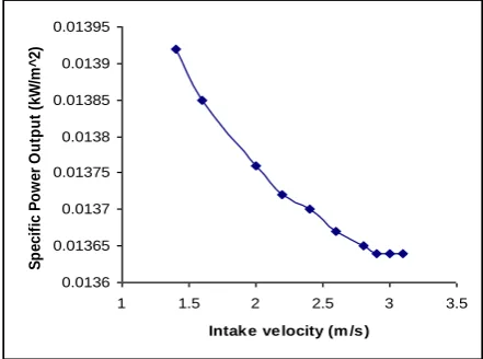
Fig. 4 Intake velocity versus Specific Power Output (at a depth of 700m)
Fig.5 Intake velocity versus Specific Power Output (at a depth of 800m)
Fig.6 Intake velocity versus Specific Power Output (at a depth of 1000m)
Figs. 3, 4, 5 and 6 shows the effect of the intake velocity on the specific power output for the depths of 600, 700, 800 and 1000m respectively. The specific power output increases with decrease in the intake velocity. The experimental values for an Open cycle OTEC power plant shows that the maximizing velocity is 2.5m/s with a safety factor of 2 for a 1MWe power plant. However, in the closed cycle, by neglecting the safety factor, the maximizing velocity is found to be between 2.8 to 3 m/s for a 0.1MWe power plant. Since the experimental values were found to be ranging from 2 to 3
0.01865 0.0187 0.01875 0.0188 0.01885 0.0189 0.01895 0.019 0.01905
1 1.5 2 2.5 3 3.5
Intak e ve locity (m /s )
S p e c if ic p o w e r o u tp u t (k W /m ^ 2 ) 0.01145 0.0115 0.01155 0.0116 0.01165 0.0117 0.01175 0.0118 0.01185
1 1.5 2 2.5 3 3.5
Intake velocity (m /s)
Fig. 7 Depth versus Overall Heat Transfer Coefficient on the condenser side
Fig. 7 shows the effect of depth on the overall heat transfer coefficient. The overall heat transfer coefficient increases with increase in the depth. The main factor influencing the overall heat transfer coefficient is the temperature difference. As we increase the depth of the cold water pipeline by extending its length, the temperature of the cold water decrease thereby increasing the heat transfer coefficient.
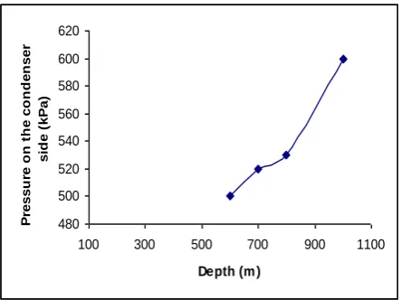
Fig. 8 Depth versus Pressure on the Condenser side
Fig. 8 shows the effect of depth on the pressure on the condenser side. The pressure increases with increase in depth. In general it is found that the pressure increases with increase in depth.
IV.CONCLUSION
A Finite Time Rankine Cycle (Closed cycle) was successfully simulated by varying the parameters. Mathematical modelling was done for the Finite Time Rankine Cycle. The simulation was done in the EES software. It was found that at a depth of 600m the maximum Specific Power Output is obtained for the intake velocity of 3 m/s.
ACKNOWLEDGMENT
The author would like to record his sincere thanks to Mr. D. Michael Bakkiyanathan for helping him in the simulation using EES software.
0.47 0.48 0.49 0.5 0.51 0.52 0.53 0.54 0.55 0.56 0.57
100 600 1100
De pth (m )
O v e ra ll H e a t T ra n s fe r C o e ff ic ie n t (k W /m ^ 2 K ) v=3 v=2.9 v=2.8 v=2.6 v=2.4 v=2.2
v = 2
v = 1.6
v = 1.4
v = 1.2
480 500 520 540 560 580 600 620
100 300 500 700 900 1100
Depth (m )
REFERENCES
[1] Nihouse, G. C., Syed, M. A., and Vega, L. A., “Ocean Energy Recovery”, Proceedings of the First International Conferences (ICOER), USA, 1989.
[2] Chih Wu, “Power optimization of a Finite time Rankine heat engine”, Int. J. heat and fluid flow vol. 10, pp.134-137, 1989.
[3] Rabas, T., Panchal, C. and Genens, L., “Conceptual Design Analysis for Hybrid-Cycle OTEC Plants for Co-Production of Electric Power and Desalinated Water at different depths”, Ocean Energy Recovery, pp.217-226, 1989.
[4] Paul M. Wolff and Lloyd F. Lewis, “Thermal Resource availability”, Energy Vol. 5, pp.525-528, 1980.
[5] Avery, W. H., and Richards, D., “Hydrogen Generation By OTEC Electrolysis, and Economical Energy Transfer to World Markets via Ammonia and Methanol”, Int. J. Hydrogen Energy, Vol. 10, pp.727-736, 1985.
BIOGRAPHY