Analysis of High-Rise Building with Outrigger:
State of Art
Varsha Virde Dr. R. Singh
PG Student Professor
Department Civil Engineering Department Civil Engineering Ujjain Engineering College, Ujjain, MP, India Ujjain Engineering College, Ujjain, MP, India
Dr. R. M. Damgir
Professor
Department Civil Engineering
Govt. Engineering College, Aurangabad, MH-431001, India
Abstract
The high-rise buildings have been viewed as the landmark of the city with the rapid development of the economy and construction technology. Thus, more high-rise buildings are being built across the world. The Designer of high-rise buildings consider strength, stiffness, stability and deflections as an important criterion that are influenced by the lateral loads induced by wind and earthquake. The stability assessment of high-rise building is generally assessed by human comfort under wind effect. The Lateral stiffness of the building reduces as the height of the building increases. To provide sufficient lateral stiffness to the high-rise structures by lateral load resisting system such as outrigger beams which connect the central core and external columns are used. In this paper, an attempt has been made to collect the information from the literature review of research papers related to the analysis of high-rise RC building for outrigger structural system under the action of lateral loads. The objective of this paper is to study the behaviour of outrigger structural system and optimum position of belt truss for dynamic analysis due to wind load.
Keywords: Belt truss, Central core, Outrigger, Tall building, Wind analysis
________________________________________________________________________________________________________
I. INTRODUCTION
Now a day tall structures are more referred due to tremendous growth of urban population and scarcity of available land. Tall buildings are usually designed for commercial office and residential building. Tall buildings development involves various compound aspects such as, human aspiration to build higher, economic growth, innovations in structural system. In the design of high-rise structures steel and concrete are two most commonly used materials. Consideration of lateral loads as wind and earthquake are predominating for high rise structure design. There are various lateral loads resisting structural system available for design of tall structures.
II. STRUCTURAL SYSTEM
The structural members were assumed to carry primely the gravity load in the early structures. But now, due to high strength materials in structural system, Slenderness is increased and building weight is reduced. Thus, lateral loads such as wind and earthquake mainly taking into consideration. In tall buildings excessive drift due to lateral load control by the lateral load resisting system, so non-structural and structural damage risk can be minimized. Various types of lateral load resisting system for tall building shown in [Fig.01].
1) Type 1. Shear frames.
Fig. 1: Types of structural systems (from CTBUH, 1980)
III. OUTRIGGER STRUCTURAL SYSTEM
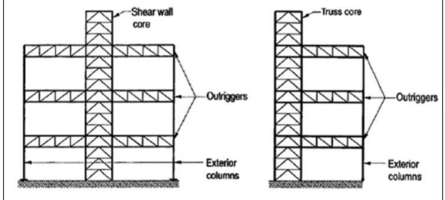
A.Introduction- An outrigger-braced high-rise structure consist a braced steel or RC frame main core, this core is connected to the exterior columns by stiff outriggers become and belt truss at one or more levels. The column restrained outriggers resist the rotation of the core thus, lateral deflections and moments in the core to be smaller than free standing core alone resist when horizontal loading acts on the building. The core may be located at centre of the building when outrigger extending on both side of the building column [Fig.02] and it may be located at one side of the building when outrigger extending on one side of the building column [Fig.03].
Fig. 2: Outrigger with central core. Fig. 3: Outrigger with offset core.
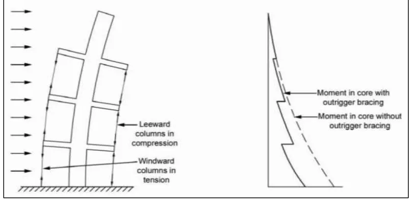
Behaviour of Outrigger
Fig. 4: Behaviour of outrigger structural system (from Dr. K. S. Sathyanarayanan,2012)
Types of Outrigger Structural System
On the basis of connectivity to the core these are two types of outrigger systems: 1) Conventional outrigger system.
2) Virtual outrigger system.
Conventional Outrigger System
In the conventional outrigger system, the outrigger beams or trusses are directly connected to the braced frames or shear wal l at the core and columns located outboard of the core. The lateral load produced the overturning moment in which, part of this overturning moment resists by the outboard columns. The outrigger trusses which are connected to the core and to columns outboard of the core, convert part of the moment in the core into a vertical couple at the columns and restrain rotation of the core [Fig.05]. Elongation, shortening of the columns and deformation of the trusses will permit some rotation of the core at the outrigger. The rotation is small enough in most designs, that the core undergoes reverse curvature below the outrigger.
Virtual Outrigger System
In the virtual outrigger system, the outrigger trusses directly connected to the outboard columns and the core and convert moments in the core into a vertical couple in the columns. In this system without a direct connection between the outrigger trusses and core the overturning moment transfer from the core to the elements outboard of the core same as the conventional outrigger system. The basic idea of virtual outrigger system is to use floor diaphragms. This floor diaphragms are very strong and stiff in their own plane and transfer moment in the form of a horizontal couple from core to the trusses and trusses to the exterior column. In conventional outrigger system, the way in which overturning moment in the core is converted into a vertical couple at the exterior columns, rotation of the core at the top and the bottom of the belt truss is resisted by the floor diaphragms. Thus, part of the moment in the core is converted into a horizontal couple in the floors. The horizontal couple transferred through the two floors to the truss chord, is converted by the truss into vertical forces at the exterior columns. The basement walls and belt trusses are used as virtual outrigger [Fig.06].
Advantages and Disadvantages of Outrigger Structural System
Advantages
1) The overturning moment resisted by all exterior columns.
2) Outrigger structures can be incorporated into composite steel or concrete structures.
3) Without the column and foundation system, uplift and net tension forces eliminated and reduced. 4) Rigid frame connections can be avoided on the exterior frame of the structures.
Disadvantages
1) The connection between the outrigger trusses and the core can be complicated, especially when a concrete shear wall core is used.
2) At the interface between core and foundation the connection is intensive work. 3) The place cannot be used at the floor level where the outrigger is located. 4) To resist overturning moments, expensive foundations solely required.
IV. LITERATURE REVIEW
Kian and Siahaan [2001] carried out a research on high rise building by introducing outriggers and belt truss system which connecting core to the exterior column to make the structure more proficient and increase the stiffness of the building under lateral loads. Under this research work the application of diagonal outrigger and belt truss with different configurations studied.
The researchers have considered a 60 storey 3-dimensional model which subjected to earthquake load by incorporating outrigger and belt truss by varying locations, numbers and height of diagonal outrigger beam and belt truss. Similarly, 40 storey 2-D Model subjected to wind load by varying location of outrigger beam and belt truss as per British Standard. In this research work they also focused on the optimum location of the outrigger and reduction in the lateral displacement. They conclude that 65% displacement reduced in 40 storey 2-D model by providing two outrigger first outrigger placed at top second outrigger placed at mid height of the structure. Again, 18% displacement reduced in 60 storey 3-D Model by providing optimum location of outrigger truss at the top and 33rd level of story.
Honederkamp and Bakker [2003] worked on the graphical method of analysis of tall building structure. The structure consists the braced frame with outrigger trusses and subjected to horizontal loading.
A model of 29 storeys was analysed and consist the centrally located braced frame with X-bracing system. This bracing system was connected to the two equal length outriggers. To analyse the structure the researchers, determine five stiffness as bending and racking shear stiffness of the braced frame and the outrigger. Axial lengthening and shortening of the exterior column also determine in addition to the stiffness. They also worked on the impact of outrigger on the behaviour of high-rise structure and optimum location of the outrigger up the height of structure. The structural parameters obtained as dimensionless parameter α, characteristic parameter and characteristic non-dimensional parameter ω & βΗ. The result was found from this research that the horizontal deflection and bending moment reduced when stiffness of outrigger structure increases. The optimum position of outrigger found to be 28.5 m from top. The restraining moment reduced by 18.2% in bending moment and the horizontal deflection at top reduced by 28.9% for bending in the braced framed structure.
Bayati et al. [2008] present a study on drift reduction with rigid outrigger in a uniform belted structure. For this analysis, researchers worked on a sample structure which built in Tehran's Vanak Park.
An 80-story steel frame office tower will be used to study the effectiveness of belt trusses as virtual outriggers. Designs compared with conventional outriggers and virtual outriggers. The building consists the 3 sets of 4-storey deep outriggers. For core diagonal bracings are set at the top of the horizontal members. Design loads are considered according to the Iranian Building Code. The results obtained from this study was that due to the wind loading the lateral displacement at top of the building found to be 70 cm for conventional outriggers and 95 cm for belt trusses as virtual outriggers. Also, analyse the structure for no outriggers at all and found that the displacement increased to 275 cm. The advantage of this research work indicated that the belt trusses as virtual outrigger avoids the most of the problems associated with conventional outriggers.
Herath et al. [2009] carried out a research on high rise building by adopting the outrigger beam system under the earthquake load. The concept of this study was to increase the stiffness and strength of the building by using the outrigger beam. This outrigger beam connecting the core and exterior column of the building to resist the lateral load acting on structure. He also studied the optimum location of the outrigger beams in structure in order to achieve maximum stiffness and economy in building.
A model of 50 storeys was analysed for three different ratios of peak ground acceleration to peak ground velocity. He analysed the structure by response spectrum method and considering the parameters such as lateral displacement and inter storey drift. From this study it was conclude that the optimum position of the outrigger was near the mid height of the building.
Haghollahi et al. [2012] have carried out a research work on optimum location of outrigger in steel tall buildings subjected to earthquake loads. This was a comparative analysis based on optimum outrigger locations obtained by response spectrum method and non-linear time history analysis method. The analysis of structure was done against seven different ground motions.
from top (14 & 16 storey) in 20 and 25 storey model respectively while by response spectrum analysis the location was 0.44 and 0.5 times the height of the structure from top (10 & 14 storey) in 20 and 25 storey model respectively. They also concluded the locate outrigger at upper level should be safe.
Kamath et al. [2012] presented a study on behaviour of outrigger structural system in high rise reinforced concrete building. The researchers also examine the optimum location of outrigger system in tall buildings by relative height of outrigger beam. The aim of this study was to increase the stiffness and make the structural form efficient under the lateral load acting on the structure due to earthquake load.
In this analysis a 40-storey model have been consider of varying the flexural rigidity of the structure and placing the outrigger at different location by taking the different height ratio. The equivalent static analysis was performed for static behaviour and time history analysis was performed for dynamic behaviour. Previous earthquake data of peak ground acceleration of California region was considered for time history analysis. In this research various parameters such as lateral deflection, peak acceleration, inter storey drift has been investigated. From the study of this research conclusion was found that the top displacement of the structure is reduced when the outrigger is placed at mid height of the building with flexural rigidity of 0.25 and for all earthquake histories of California region the top lateral displacement was least for outrigger structure with relative height of 0.5.
Nanduri et al. [2013] research that in the high-rise buildings such as tall structures the stiffness of the building decreases due to the height of building. In order to increase the stiffness of the tall structures some lateral system such as outrigger system should incorporate in the building. This outrigger system resists the lateral loads such as earthquake load acting on building. In this paper they also study the optimum position of the outrigger and efficiency of each outrigger under the action of lateral load.
In the analysis of this research a 30-storey reinforced concrete building has to be analysed the multi-outrigger system was installed with several combinations such as with outrigger, without outrigger and outrigger with belt truss at the different position in the building. The building checked for lateral displacement, drift, bending moment, column axial force. The conclusion of this study was that when outrigger and belt truss placed at top and mid height of the building then lateral displacement of building reduced. The researchers also conclude that the concrete outrigger system gives better result as compare to the steel section because of the rigid connection of the outrigger beam with core of building.
Halkude et al. [2014] carried out a research on effect of seismicity on the irregular shape structure in high rise RC building. The investigator works on the seismic response of structure to increase stiffness of the building by incorporating the shear wall in the structure.
An 11-storey irregular and unsymmetrical 3-dimension model (C-shape plan) was analysed. The analysis was done by equivalent lateral force method as per Indian Standard. In this study the shear wall introduced by varying percentage length of shear wall with possible combinations of shear wall. The parameters considered for this research such as storey drift, torsion, base shear, beam moment, column moment and top displacement. The researchers concluded from this work when shear wall used in irregular building at proper location then twisting effect of building minimized and stiffness of the structure increased when length of shear wall increases. They also found that the application of shear wall about 23-31% of perimeter structure was found very much effective in minimizing bending moments and controlling displacement.
Kamath et al. [2014] presented a study on the performance of a multi-outrigger structural subjected to seismic load. The analysis was done for models with different combinations of outriggers placed at various locations for different values of relative axial rigidity (ratio of axial rigidity of column to the axial rigidity of the core wall) of the shear core wall. It was considered that the axial rigidity was directly related to the cross-sectional area and modulus of elasticity of the members.
A 3-D Model of 40 storey reinforced concrete building was analysed for multi-outrigger system with outriggers at different levels. In this research paper the result of analysis was obtained for the parameters such as bending moment, shear force, storey drift, lateral displacement in the core wall of the structure. The conclusion comes from the study was that for displacement criteria a significant reduction in lateral displacement at top has been observed for relative height of 1.5 when compared the multi-outrigger structure with a structure without outrigger and for bending moment criteria there has been a reduction in bending moment observed for relative height of 6.67 when compared the multi-outrigger structure with a structure without outrigger.
Ping et al. [2014] presented a study on an analytical solution for a novel damped outrigger system. The damped outrigger system is applied in a super high rise building in which the bending deformation of the core is predominating over the shear deformation. For this type of analysis, the viscous dampers are vertically installed between the core and perimeter columns of the high-rise building.
In the analysis of this work an improved analytical model considered for damped outrigger system. This damped outrigger effect as a general rotational spring which acting on a Bernoulli-Euler beam. For the governing equation of damped outrigger system, the dynamic stiffness method (DSM) was introduced. Also derive the equivalent rotational spring stiffness including the combined effects of dampers and axial stiffness of perimeter columns. The dynamic characteristic of damped outrigger system was governed by parametric analysis. The parametric analysis was conducted to evaluate the influences of optimal damping co-efficient, optimal damped outrigger position, stiffness ratio of core to perimeter column. The conclusion of this study was that when the stiffness ratio increases the maximum modal damping ratio decreases and the modal damping ratio affected by the stiffness ratio of core to perimeter columns. They also found the optimal position of the damped outrigger varies with damping co-efficient and stiffness ratio of core to the perimeter columns.
This study consists the 3 models of reinforced concrete multi-storeyed symmetrical building. The models have 15, 20, 25 storey and 45, 60, 75 m height of the building respectively. The building has L-shape frame. Under the analysis of this research the building consists the double core arrangement of shear wall, stringer beam and floor rigidity. The result was carried out by the study of the model was that the building frame with double core arrangement of shear wall and stringer beam shows minimum column forces and moments. Thus, the lateral displacement and storey drift are also comparatively less because this type of structure is very stiff. Also found that the moment in the corner columns are less as compared to the middle column.
Biradar and Bhandiwad [2015] have worked on the performance of the multi-outrigger structural system for static and dynamic behaviour of tall structure. In the study of this research the structure was subjected to lateral loads such as earthquake load and wind load. For the time history analysis data of Bhuj earthquake for ground motion was carried out. The structure consists the central shear wall with belt truss outrigger and concrete outrigger. The analysis was done for the lateral displacement, story drift and base shear for static and dynamic loading and also variation of time period of the different building.
The research was carried out on a 40 storey 3-D Model. In this research work the results were obtained as when the outriggers are placed at 20th and 26th stories the lateral displacement reduce of about 15% against lateral loads. And for belt truss outrigger the reduction in displacement of about 6.4% when belt truss placed at 20th and 26th stories. Similarly, for the dynamic time history analysis the displacement reduced about 3% when outrigger positioned at 20th and 26th stories. They also found that outrigger bracing with belt truss is more suitable then concrete outrigger.
Kogilgeri and Shanthapriya [2015] presented a research work on static and dynamic behaviour of the outrigger structural system on high rise steel structure by reducing the depth of outrigger. This study was based on the high-rise steel structure with central core and with outrigger structural system of varying the depth of outriggers.
This research consist model of 40 storey 3-D steel structures. Inverted-V bracings were used for both outrigger system and central core of the structure. To analyse the structure depth of outrigger were reduces to 2/3rd and 1/3rd of storey height along with full storey height and the depth of the belt truss was maintaining as same as the typical storey height. The researchers perform equivalent static and response spectrum analysis to analyse the structure. The analysis was performed for parameter as lateral displacement and storey drift. The conclusion from this work shows minor difference when compare performance of outrigger with full depth and the outrigger with reduced depth. They also found the structure with cap truss and intermediate outrigger increases 16% performance of building as compare to the structure with only cap truss and maximum reduction in storey drift and lateral displacement observed in full storey depth outrigger structural system.
M R and B C [2015] carried out a study on dynamic analysis of tall structure subjected to earthquake load and located under the different seismic zones. In this study the belt truss is introducing at the top and mid height of the building. The belt truss is provided along the peripheral columns of the structure at certain height of building to improve the stiffness against lateral loads. In this study the researchers used the different type of belt truss such as X, V, inverted V, diagonal shape.
The analysis was carried out on a 30-storey reinforced concrete building by introducing different type of belt truss. The model is analysed by the equivalent static and response spectrum method. A comparative study has been done for different seismic zones and it is found that concrete belt truss is more efficient as compared to steel belt truss. And also reduce lateral displacement and story drift. The study also concluded based on economic conditions inverted V type belt truss is best in all seismic zones and increase the efficiency of the building.
Mulla and B N [2015] presented a study on behaviour of the outrigger system in tall RC regular and irregular structures. For this structural system the researchers used steel bracings for the belt truss, also give a brief introduction on concept of the conventional and virtual outrigger system. The aim behind this study was to resist the overturning moment.
This investigation consists two Models of 20 storey in which one was regular building with and without outrigger and another was irregular building with and without outrigger. Both models have centrally rigid shear wall. The structure subjected to seismic load. To analyse the structure researchers performs a linear analysis by equivalent static method and response spectrum method. The structure also analysed for various seismic zone according to Indian standard. The building checked for base shear, lateral displacement, storey drift, natural time period. From the study of this work the conclusion was found that the irregular building is more effective than regular building but stiffness of the building reduces. Also, for lateral displacement the concrete outrigger was more efficient then steel outrigger and this result enhance the monolithic behaviour of the structure. They also concluded the lateral displacement and storey drift of the structure were reduces.
R M and A R [2015] have presented a research work on the comparative study and analysis of different lateral load resisting structural forms. The research was carried out on an irregular building and performs dynamic analysis by response spectrum method to analyse the structure.
The researchers considered a model of 15 storey high rise RCC building which was geometrically irregular in plan. For this research they considered structural forms such as outrigger structure, tube structure, rigid frame structure, core wall structure, shear wall structure with different configurations of shear wall location. This study included the parameters as torsion rigidity, storey deflection, storey drift and shear force. From the analysis of this study the conclusion was found that the outrigger behaves as high drift controller when provided at storey, which has maximum drift. Because of lower displacement the tubular structure was considered as best lateral load resisting system. By providing the L-shape shear wall at corners sway can be avoided in columns.
The analysis was carried out on a 30 storey 3-D Model in which the building plan changes at 11th and 21st storey. The building was analysed with several combinations such as bare frame, bare frame with one outrigger and belt truss, bare frame with two outrigger and belt truss. Linear static analysis has been conducted for lateral loads which acting on the structure. In this research paper the result was obtained for lateral displacement, maximum storey shear, storey drift and axial load of different column. The conclusion comes from this study was that the use of outrigger and belt truss in high rise building increases the stiffness and make structure efficient under lateral loading. Also found optimum position of outrigger between 0.5 times its height and optimum position of second outrigger was middle height of building. It reduces 11.5% storey drift and 12.78 % deflection of building.
Jagadheeswari and Christy [2016] presented a study on the performance of multi-outrigger structural system for tall structure to find the optimum position of the outrigger system and belt truss by using lateral loads. Static and dynamic analysis was performed for concrete outrigger with central shear wall, without outrigger and outrigger bracing with belt truss. Time history analysis was carried out from records of past historical earthquake occurred in the Nepal region.
To execute this study researchers have modelled a 40 storey 3-D Model. Static analysis carried out by equivalent static method and dynamic analysis carried out by time history method for different arrangements of outrigger and belt truss and braced outrigger. This research work concluded the 20th and 26th storey of the building as the optimum position of the outrigger. Also, multi-storey outrigger structural system reduced the inter story drift and control the top storey displacement. The time history analysis for the building obtained the lateral displacement 0.0138 mm for building without outrigger and when the first outrigger placed at 20th storey and second outrigger placed at 26th storey this lateral displacement reduced to 0.01342 mm.
Patil and Sangle [2016] carried out a research to analyse the seismic behaviour of outrigger braced building and the optimum location of outrigger in the high rise 2-D steel building. For seismic response of buildings, they perform a non-linear static pushover analysis on different outrigger braced high rise buildings.
The researchers consider different high rise 2-D steel buildings of 20, 25, 30 and 35 storeys with various position of outrigger beam from first to top storey of the building. Under the analysis of this work the parameters considered as fundamental period, base shear, roof displacement, storey displacement, inter storey drift ratio, performance point and also used the different lateral load patterns such as elastic first mode, multimodal and uniform for the analysis. The research work concluded the optimum position of outrigger 0.3H to 0.6H. The base shear increases and the roof displacement decreases when outrigger provided at top storey and the different lateral load patterns affects the seismic behaviour of outrigger braced 2D building. As comparison to outrigger braced frame the MRF building frame shows higher storey displacement, inter storey drift ratio and lower base shear.
Kamgar and Rahgozar [2017] have worked on the idea to obtain the optimum location of the flexible outrigger and belt truss system by using energy creation. For this analysis the researchers considered that the structure subjected by different lateral loading such as uniformly distributed load, triangularly distributed load along the height of building and concentrate load at top of building. This study was carried out on tall building structure with some combined system and this combination was done by continuum approach and consist of framed tube, shear core, belt truss and outrigger system. The analysis of the structure was done by the strain energy method. To analyse the structure from this method a rotational spring was placed at location of outrigger belt truss system with constant rotational stiffness and optimum location of spring obtained when energy absorbed by spring is maximized. The researches computed the stiffness of equivalent spring and rotation of tall building. From this research work the result found that when axial stiffness of exterior column increases then optimum location of outrigger system goes downward. Also concluded when parameters µ and ƞ increases then optimum location of outrigger for this combined system goes upward, downward and remain unchanged along the height of building and for the value of ƞ the optimum location of outrigger determined as 0.441, 0.49, 0.667 for uniformly distributed load, triangularly distributed load and concentrate load respectively.
V. FUTURE SCOPE
On the basis of literature review the research work related to outrigger structural system could be extend in following areas: 1) Researchers have also performed study on the behaviour of outrigger structural system by considering simple grids instead of
real building plan.
2) The outrigger structural system can be extending to super high-rise building having 80-90 stories (300m to 350m).
3) Mostly the analysis of the high-rise building has done under the seismic zone-III. There are few researches been done under the seismic zone-IV and V.
4) The outrigger system has analysed for wind load as per IS 875 (P3): 1987. We can analyse as per IS 875 (P3): 2015 on basis of gust factor parameter.
5) Mostly researcher perform the analysis for optimum location of outrigger, so there is need to perform the analysis for changing the stiffness of core as well as outrigger.
6) There is also a gap for the study soil structure interaction by considering the parameter overturning moment 7) Virtual outrigger and damped outrigger are not yet analysed for super high-rise structure.
REFERENCES
[1] Abbas Haghollahi, Mohsen Besharat Ferdous, Mehdi Kasiri, “Optimization of Outrigger Locations in Steel Tall Buildings Subjected to Earthquake Loads” 15th World Conference of Earthquake Engineering, 2012.
[3] A. S. Jagadheeswari And Freeda Christy, “Optimum Position of Multi-Outrigger Belt Truss in Tall Buildings Subjected to Earthquake and Wind Load” International Journal of Earth Sciences and Engineering, June 2016.
[4] Dhanaraz M. Patil And Keshav K. Sangle, “Seismic Behaviour of Outrigger Braced Systems in High Rise 2d Steel Buildings” Institution of Structural Engineers, Vol.8, 2016.
[5] Dr. S. A. Halkude, Mr. C. G. Konapure, Ms. C. A. Madgundi “Effect of Seismicity on Irregular Shape Structure” International Journal of Engineering Research & Technology, Vol.3, Issue6, June 2014.
[6] J. C. D. Hoenderkamp And M. C. M. Bakker, “Analysis of High Rise Braced Frames with Outrigger” The Structural Design of Tall and Special Buildings, July 2003.
[7] Kiran Kamath, N. Divya, Asha U Rao, “A Study on Static and Dynamic Behaviour of Outrigger Structural System for Tall Buildings” Bonfiring International Journal of Industrial Engineering and Management Science, Vol.2, No.4, December 2012.
[8] Kiran Kamath, Avinash A. R., Sandesh Upadhyaya K., “A Study on The Performance of Multi-Outrigger Structure Subjected to Seismic Loads” IOSR Journal of Mechanical and Civil Engineering, 2014.
[9] Mohd Abdus Sattar, Sanjeev Rao, Madan Mohan, Dr. Sreenatha Reddy, “Deflection Control in High Rise Building Using Belt Truss and Outrigger Systems” International Journal of Applied Sciences, Engineering and Management, Vol.3, No.6, Nov. 2014.
[10] N. Herath, N. Haritos, T. Ngo & P. Mendis, “Behavior of Outrigger Beams in High Rise Buildings Under Earthquake Loads” Australian Earthquake Engineering Society, 2009.
[11] P. M. B. Raj Kiran Nanduri, B. Suresh, MD. Ihtesham Hussain, “Optimum Position of Outrigger System for High-Rise Reinforced Concrete Buildings Under Wind and Earthquake Loadings” American Journal of Engineering Research, 2013.
[12] Po Seng Kian, Frits Torang Siahaan, “The Use of Outrigger and Belt Truss System for High Rise Concrete Building” Dimensi Teknik Sipil, Vol.3, No.1, Maret 2001.
[13] Prateek N. Biradar, Mallikarjun S. Bhandiwad, “A Performance Based Study on Static and Dynamic Behaviour of Outrigger Structural System for Tall Buildings” International Research Journal of Engineering and Technology, Vol.2, Issue5, Aug. 2015.
[14] Reza Kamgar And Reza Rahgozar, “Determination of Optimum Location for Flexible Outrigger System in Tall Buildings with Constant Cross Section Consisting of Framed Tube, Shear Core, Belt Truss and Outrigger System Using Energy Method” International Journal of Steel Structures, 2017.
[15] Shivacharan K., Chandrakala S., Karthik N. M. “Optimum Position of Outrigger System for Tall Vertical Irregularity Structures” IOSR Journal of Mechanical and Civil Engineering, Vol.2, Issue2, Mar. April 2015.
[16] Srinivas Suresh Kogilgeri, Beryl Shanthapriya, “A Study on Behaviour of Outrigger System on High Rise Steel Structure by Varying Outrigger Depth” International Journal of Research in Engineering and Technology, 2015.
[17] Tan Ping, Fang Chuangjie And Zhou Fulin, “Dynamic Characteristics of a Novel Damped Outrigger System” Earthquake Engineering and Engineering Vibration, June 2014.
[18] Thejaswini R. M. And Rashmi A. R. “Analysis and Comparison of Different Lateral Load Resisting Structural Forms” International Journal of Engineering Research and Technology, Vol.4, Issue7, July 2015.
[19] Vijaya Kumari Gowda M. R. And Manohar B. C., “A Study on Dynamic Analysis of Tall Structure with Belt Truss Systems for Different Seismic Zones” International Journal of Engineering Research and Technology, Vol.4, Issue8, Aug. 2015.