MD3 Model Loading in Game
Xilong QuCollege of Computer & Communication, Hunan Institute of Engineering, Xiangtan, China Email: [email protected]
Linfeng Bai
School of Information Engineering, Henan Institute of Science and Technology, Xinxiang, China Email: [email protected]
Zhongxiao Hao, Lei Xiao
College of Information Science & Electrical Engineering, Hebei University of Engineering, Handan, China Email:[email protected]
Abstract—Three-dimensional game requires a faster, simpler file format. In the article it introduces the definition and the format of the MD3 model file and the loading process is discussed in detail. It also describes the definitions and format of the MD3 model file that the Quake 3 engine uses. And through the development process of a virtual role in the movement controlling platform to demonstrates how to load MD3 file in the game and to achieve the animation control. For the sake of improving the third dimension of 3D scenes, we analyze the existent real-time shadow generating algorithms, and improve the Chan's smoothie soft shadow algorithm, make it based on shadow map, and treat with both the inner and outer penumbra. It not only effectively resolves the problems such as some algorithms can not cast shadow on itself and some are too complex, it also solves the aliasing problems of shadow mapping, and it meet the requirements of real-time in more complex scene. At last, the algorithm is emulated with DirectX, and the experimental results show the feasibility of the algorithm.
Index Terms—Game, MD3, load
I. INTRODUCTION
MD3 is a common file format; it has gone through extensive testing. In the Quake 3 and many other games, .md3 has been proved to be an excellent model format. This model file will be stored in different animation frames. Every animation has a fixed name, different length, and different speed in every move. *.Md3 documents used in control platform include lara_head.md3, lara_lower.md3, lara_upper.md3, and railgun.md3。
An md3 model is usually composed of a body of three parts and a weapon model. Therefore it need to open three model file and put them together (if the weapon is used, it need to open four files). They are named as head.md3、upper.md3、and lower.md3.After deeply
understanding of the MD3 file; you will find a model can have a lot of component. Md3 file stores the animation role in key frames. In old elf engine using elves method turns out to have a long list of pictures. Every image is changed based on the previous one, just like old film, the viewer can feel object is in motion. It's also the same
principle for the polygon vertex of the .md3 files. To ensure the model fast with reasonable image quality, engine has no restrictions on the number of frames but not more than 300 frames. If using more key frames of words, it will result in considerable storage overhead. Animation .cfg stores the information about animation, which is used for the call of key frames. It uses three different .md3 file to provide three different fines of model. For minimum fidelity model, add a ‘2’ in the end of the filename. For intermediate precision of the model, add a ‘1’ in the end of the filename. For the highest fidelity model, do not need to add any additional figures. For the highest fidelity model, it does not need to add any additional figures. Therefore, filenames named as head.Md3, head1.Md3, head2.Md3 respectively correspond to the highest, medium, lowest fidelity.
Head, upper and lower the three parts uses the so-called "tag (meta)" to attach. Each tag is actually a single of geometrical body (a right triangle), triangle bottom is a fulcrum pivot point, and the fulcrums decide where each model will center around and rotate. Each .Md3 model usually has three tags, the name of the tags corresponding to their place. In the bottom of head and neck, it uses “tag head” to attach the head to the upper-body. In the bottom of the spine, it uses “tag_torse” to attach the upper to leg. And it uses tag_weapon to attach the weapon to the hands.so it needs to put tag_head on the fulcrum of the skull and put the tag_torso on the fulcrum of the spine. By analogy, each tag attached the .md3 file is assigned by a record of *.skin file, therefore it can attach any part of .md3 model via any means that you expect.
II. THE DEFINITION OF MD3 MODEL FILE
MD3 files store the geometric data of model, while tag or jpg files store the texture used by md3 files. Shader document control the mapping of texture and many other parameters. By using skin files, it can mark several md3 documents to a group, which forms a complete model; in addition, in order to make different parts of the model which stored in each md3 documents produce animation, it still needs to use an animation.cfg document.
The animation in the Quake 3 model is fulfilled by key frames. This type of animation is realized by storing a model in each position of the frame, then map each model by frame according to this series of position, thus it can form animation effects. The animation of Quake 3 files can in arbitrary length and arbitrary frame rate.
In the role motion controlling platform showed in this chapter, BOTH_DEATH * animation serves to leg object and upper object at the same time. Death animation’s last frame is in the BOTH_DEAD * animation.
TORSO_ * animation is used in upper object. TORSO_GESTURE can be arbitrary length; of course it can also have its own voice. TORSO_ATTACK is for attack animations with a ranged weapon, it is just 6 frame length, because it requires synchronizing with weapon firing. The first frame of animation is targeting, second frame is firing and kicks back, and the remaining frame is used in returning to the first frame. TORSO_ATTACK2 is also a 6 frame attack animations, TORSO_DROP is the first part of weapon switching, it must just in 5 frame length. The second part of weapon switching is TORSO_RAISE, it must also be in 5 frame length. TORSO_STAND is the standing animation when subjected to wield weapons.
LEGS_ * is the animation used in the legs. LEGS_WALKCR is the circulation animation of crouching walking, Next is walking (LEGS_WALK), running (LEGS_RUN), swimming (LEGS_SWIM), leaping forward (LEGS_JUMP), landing forward (LEGS_LAND), leaping backwards (LEGS_JUNPB), landing backward (LEGS_LANDB), draw back or running backward (LEGS_BACK) as such circular animation etc., and the leisure (LEGS_IDLECR) in spare crouching (LEGS_IDLE) and the rotating animation (LEGS_TURN) when rotation angle is enough to request the rotation of the leg.
All the animation frames are stored in the array; it can invoke the corresponding animation via the frame number of the array:
cgf. File used in controlling platform is as follows: //lara_animation.cfg
// animation config file for Lara "Angelina Jolie" Croft sex f
// first frame, num frames, looping frames, frames per second
footsteps boot
0 31 0 25 // BOTH_DEATH1
31 1 1 25 //
BOTH_DEAD1
32 35 0 20 //
BOTH_DEATH2
67 1 1 20 //
BOTH_DEAD2
68 25 0 25 //
BOTH_DEATH3
93 1 1 25 //
BOTH_DEAD3
94 39 0 15 //
TORSO_GESTURE
133 7 0 15 //
TORSO_ATTACK
140 11 0 15 //
TORSO_ATTACK2
151 5 0 15 //
TORSO_DROP
156 6 0 15 //
TORSO_RAISE
162 31 0 10 //
TORSO_STAND
193 11 0 10 //
TORSO_STAND2
94 12 12 15 //
LEGS_WALKCR
107 12 12 15 //
LEGS_WALK
120 12 12 17 //
LEGS_RUN
133 12 12 17 //
LEGS_BACK
146 12 12 14 //
LEGS_SWIM
159 6 0 8 //
LEGS_JUMP
167 6 0 12 //
LEGS_LAND
172 6 0 10 //
LEGS_JUMPB
178 6 0 10 //
LEGS_LANDB
185 6 6 5 //
LEGS_IDLE
192 6 6 5 //
LEGS_IDLECR
199 6 6 20 //
LEGS_TURN
All the mark and texture information need to use are stored in Skin file. These texts file record connection model’s tag, as well as connecting skin information. The name of the skin file is the same as Md3 file’s name which can use it. The head’s skin files only describe a marker and a texture, the mark provided by head. md3 documents, and that zhang texture will be used in the head, upper-body skin files describe three grids and three markers, these three grids will use the same piece of tga texture files. The down-body skin files describe he grid in lower.md3, and it only has a mark.
lara_lower.md3 lara_upper.md3
Md3 files use the texture which can have a 32-bit RGB color depth. In the Quake 3 engine, the width and height of texture should be powered of 2 times, and the width and height should no more than 256 pixels. Each grid of a model can have different textures and shader attributes.
Shader file is a text file, like animation.cfg and skin files; they can be operated through the text editor. Shader file is written by a kind of special language, composed by many commands. Shader is a kind of simple scripting; it provides many commands to control the various parameters of object’s texture. Shader has three kinds of attribute types. Surface properties are used to control the behavior which connected to all polygons surface of the shader. Stage or content properties are used to control the exterior surface. While the deformation attribute is to deform the vertex of a surface through some way.
III. THE FORMAT OF MD3 MODEL FILE
The range of MD3 model format is very wide, such as some pure text files only specifies the objects vertex, or preserved the vertex, texture coordinates and skeleton animation information of complex binary files, etc.
Due to 3DS MAX's max file format or other developed tools which produce obj files are a bit complex, and not easily read by OpenGL, thus converting the file format has become a key issue. Traditional skeletal animation system, such as md2 format is usually an animation of object’s movement, such as a gesture or swimming animation, is have no relations with skeleton, but related to vertex’s key frames. But in. md3 format file, down part, upper part of the body, head and weapons are respectively completely different model, can respectively realize the their animation, so that the diversity of animation get greatly enriched, and at the same time we can save system’s storage and improve the efficiency of the system operation. Use ExportMD3 software can conveniently convert the file of max format to md3 format. This format is the first-person shooter games used for its role model produced by Quake 3, id Software. It incorporates many performance settings, and is an easy-to-use format.
At higher levels, the content of md3 document is divided into the following four categories: md3 front, md3 skeleton frames, md3 markers, md3 grid. Md3 front store all key information of the whole md3 file, the concrete structure is as follows:
struct tMd3Header {
char fileID[4]; // file ID –must be "IDP3"
int version;
// file version – must be 15
char strFile[68]; //
file name
int numFrames; // animation frame amount
int numTags; // each BoneFrame’s Tag amount
int numMeshes; // Mesh(geometry mesh)amount
int numMaxSkins; //
the available amount of skin
int headerSize; // the legth of headersize of the file.
int tagStart;
// Tag structure’s starting place
int tagEnd;
//Tag’s ending place that is the starting place of geometry mesh
int fileSize;
//file size
};
Version variables are used to keep the version number, it uses 15 as the version number in the system. HeaderSize always has 108 bytes. The amount of animation key frames of whole model should be equal to each grid animation key frames of this model t. MaxSkin_Num always be 0, this property hasn't been used. The front structure as the starting point to read the subsequently different document content, it can also be used to check whether the length read by md3 file reading programs is correct.
After completing the front structure, then read skeleton frame structure from md3 files.
struct tMd3Bone {
float mins[3];
// the minimum of the skeleton frame coordinate
float maxs[3]; //
the maximum of the skeleton frame coordinate
float position[3];
//skeleton position
float scale;
//skeleton scale
char creator[16];
// charcreator of skeleton frame };
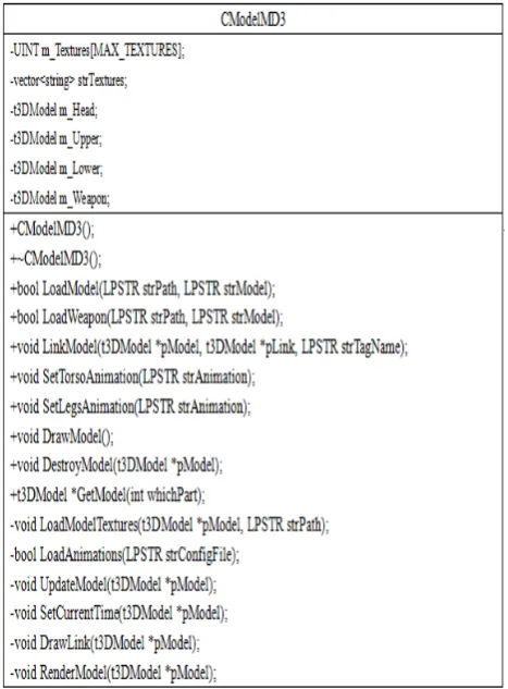
In the controlling platform of role running, we always make use of class of CModelMD3 to load, draw and release the object of role model. The UML figure of class of CModelMD3 is shown as Table 1.
Its definition is introduced in details as follows: class CModelMD3
{ public:
CModelMD3(); // construction function ~CModelMD3(); // releasing function // Loading the model
bool LoadModel(LPSTR strPath, LPSTR strModel);
// loading the weapon
bool LoadWeapon(LPSTR strPath, LPSTR strModel);
void LinkModel(t3DModel *pModel, t3DModel *pLink, LPSTR strTagName);
TABLE I.
THE UML FIGURE OF CMD3 MODEL CLASS
void SetTorsoAnimation(LPSTR strAnimation); // set up the leg animation
void SetLegsAnimation(LPSTR strAnimation); // draw model
void DrawModel();
// releasing the memory
void DestroyModel(t3DModel *pModel); t3DModel *GetModel(int whichPart);
private:
void LoadModelTextures(t3DModel *pModel, LPSTR strPath);
// loading the animation configure file
bool LoadAnimations(LPSTR strConfigFile); // update the current frame
void UpdateModel(t3DModel *pModel); // setting the current frame
void SetCurrentTime(t3DModel *pModel); // recursive drawing model
void DrawLink(t3DModel *pModel); // drawing model
void RenderModel(t3DModel *pModel); // store the texture array
UINT m_Textures[MAX_TEXTURES];
vector<string> strTextures; // role model(head and body)
t3DModel m_Head;
t3DModel m_Upper;
t3DModel m_Lower;
// weapon model
t3DModel m_Weapon;
};
IV. THE LOADING OF MD3 MODEL
When the model is established, the first thing to do is loaded it into memory model. In order to integrate all the codes at ease, a class that will integrate all the functions of loading, displaying and controlling model need to be developed, considering the system scalability. In role motion control platform, CModelMD3 class is used to load, draw and release role model object.
The class basically encapsulates all the functions generated by MD3 model so far. In public functions of the class, Load * function will load the model and its grain into memory for use. According to the given texture filename, Load Model Textures() function will load the corresponding texture and apply it to the model, LoadAnimations() function is to load the animation file, the performance of each other functions are given by the way of comments in definition.
Here we will explain the LoadMD3Model () function of CModelMD3 in detail, it will import specified character models (strModel) from the specified path (strPath)
V. ANIMATION REALIZATION
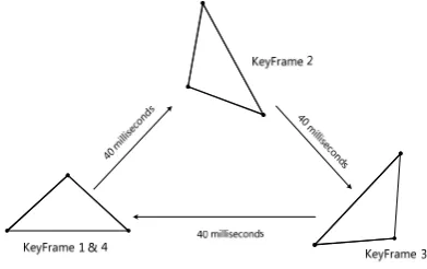
The animation realization method used in the MD3 model is called the key frames interpolation. The frame of the model is actually the key frames, in other words, it is a frame of discrete time interval place in a model animation, so we need to calculate between adjacent key frames, or interpolate corresponding animation sequence. This method is usually also called fusion, deformation or middle transition. For example, this is a very simplified structure, only contains time and matrix. But from this structure, we can see the most fundamental meaning of keyFrame technology. Suppose we need to create a triangle rotated and moved animation, as the chart shows below, the triangle make a rotating movement between three locations. We need to define four key frames, each key frame sets square deflection and migration relative to the initial position through matrix. Although KeyFrame4 is exactly the same with keyFrame1 animation, time is different, so we need to define keyFrame4. Updating animation, first, we need to calculate the current frame in place which between the other two key frames according to the time animation has broadcasted. If the current time is equal to or greater than the time setted by a key frame, then the key frame is a key frame before the current frame, and the next frame is the later key frame. If the former key frames are the last key frame, then the later key frame also uses this frame.
DWORD keyframe2 = (Keyframe == LAST_KEYFRAME_ID) ? Keyframe : Keyframe + 1 ;
Figure 1. Note how the caption is centered in the column.
triangle, that is the Mesh of each frame of the animation are the same. In the case of a little bit more complicated situation, such as a animation of personal ambulating, we can choose several movements as key frames, if we use simple animations, each key frame need to record a set of mesh information; If use skeletal animation, each key frame need to record commutation of skeleton. In these cases, the content need for interpolating calculation is much more complex. But according to time, interpolating calculates the current frame is still the foundation. Key frame technology can be used except for playing the animation; it can be also used for the movement of objects, especially fixed route of object motion.
Although the animation frame can which can display model is very good, but in order to be more real, it still need to control the displaying content and its displayed corresponding time of model animation. An effective way is to conduct such control by state, each state definite an animation or actions of the model of. For example, we can define a idle state, at this time the model won't do anything. In addition, there are many other states, including running, back warding, walking, jumping, spinning, crouch walking and dying state, etc.
VI. THE SMOOTHIE ALGORITHM
Eric Chan proposed a method to generate approximate soft shadows by using smoothies. This method combines shadow maps with geometric primitives to render fake soft shadows. In fact, this method does not computer geometrically-correct shadows, instead, it focus on the qualitative aspects of penumbrae without modeling an area light source. For example, we computer the penumbra size using the ratio of distances between the light source, blocker, and receiver, but we consider neither the shape nor orientation of the light source.
The smoothie algorithm has five steps:
1. Create a shadow map. This is done by rending the blockers from the light source and storing the nearest depth values to a buffer.
2. Identify silhouette edges. We identify the silhouette edges of the blockers with respect to the light source in object space. Since we assume that blockers are represented as closed triangle meshes, a silhouette edge is simply an edge such that one of its triangles faces towards the light and the other triangle faces away.
3. Construct smoothies. We construct a smoothie edge for each silhouette edge and a smoothie corner for each silhouette vertex.
4. Render smoothies. We render each smoothie from the light’s viewpoint. This is similar to generating the shadow map in Step 1, but this time we draw only the smoothies, not the blockers, we compute two quantities for each rendered pixel, a depth value and an alpha value, and store them together in a smoothie buffer.
5. Compute shadows with depth comparisons. We render the scene from the observer’s viewpoint and computer the shadows. We use one or two depth comparisons to determine the intensity value v at each image sample.
VII. THE IMPROVED SMOOTHIE ALGORITHM WITH SHADOW MAPPING ALGORITHM
Shadow mapping algorithm is a very popular dynamic shadowing techniques. It is an image space technique that involves rendering the scene depth from the light’s point of view and using this depth information to determine which portions of the scene in shadow.
In this case, the transition of shadow to non-shadow area is unnatural, and this method suffers from aliasing artifacts and z-fighting. Besides, this method doesn’t generate perfectly soft shadows (no umbra-penumbra). The shadow mapping algorithm has four steps:
• Generate the shadow map as usual by writing the scene
depth into a floating point buffer.
• Render the shadowed portions of the scene after depth
comparison into fixed point texture, without any lighting.
• Blur the above buffer using a bloom filter.
• Project the blurred buffer onto the scene in screen
space to get cool soft-edged shadows, along with full lighting.
In this paper, we improve the smoothie algorithm with shadow mapping algorithm, which is we process both inner and outer penumbra. First, we rending the scene depth from the light’s point of view by shadow mapping algorithm, and generate a original luminance map form the user’s point of view, then, smoothing the original luminance map by the improved smoothie algorithm until the luminance value of each point is same as the corresponding coordinates’ in alpha texture, last, we use the final luminance map to re-render the scene.
The original luminance map recorded the point of the scene is in shadow of non-shadow from the light’s point, and there are only two elements 0 and 1.
Let V={( , ): 0,1, ,i j i= nh−1;j=0,1, ,nw−1} ,
( , ) {0,1}
f x y
=
wheren
h andn
w are height andwidth of luminance map, and
f x y
( , )
is pixel value in (x,y). Then V andf x y
( , )
meet the following conditions:( , )
( , )
{( , ): ( , ) ,( , ) },
k
f x y
L
x y V
V
x y f x y
k x y V k L
∈
∀
∈
TABLE II. EXECUTION EFFICIENCY OF DIFFERENT ALGORITHMS
Geometry triangles
Shadow mapping
(fps)
Smoothie algorithm
(fps)
The improved algorithm
(fps)
4602 115.7 112.6 110.6
10297 110.8 107.5 106.3 17356 108.5 98.2 105.7
( , )
f x y
has only two values 0 and 1, and the transition is unnatural. We can introduce a transition zone W. W meets the following properties:0
( , ) {0,1}
( , )
( , ) [0.0,0.5]
(0)
( , ) [0.5,1.0]
(1)
W
V
W
V
f x y
x y
W
f x y
W
V
f x y
W
V
∈
≠
=
∀
∈
=
=
∩
∩
∩
(2)
where V (0) is the regional of 0,and V (1) is the regional of 1.
Set E is the border crossing point of 0-pixels and 1-pixels, and d is the distance from the current point to E, then you can assign the point in W through d according to a certain mathematical model, where the maximum of d is the regional border of W. As the size of d determine the size of the penumbra region, and it always bring the distortion of shadow if the d value is too large or too small, therefore, we have to determine a suitable maximum of d. When we give a suitable assignment to the pixels of W, we can achieve the smooth transition from 0-pixels to 1-pixels.
Here is the algorithm’s flow chart: VIII. EXPERIMENTAL RESULTS
Compared to the smoothie algorithm, we process the inner and outer penumbra. First, we rendering the luminance map, and smoothing it.
Let the outputted texture coordinates be vvProjGoord, we can get the luminance from texture renderer by comparing the Z-value of inputted texture coordinates to the corresponding value of depth map.
float A = tex2Dproj( ShadowSampler, vProjCoord.xy ).r;
float B = IN.vProjCoord.z - 0.001f; float fLuminanceTerm += A < B ? 0.0f : 1.0f;
Then smoothing the luminace map: for(int i=0;i<STEP_MAX-1;i++) {
g_pd3dDevice->SetRenderTarget( 0, g_pScreenSurfErode[i+1] );
g_pd3dDevice->SetDepthStencilSurface( g_pErodeDepthRT ); g_pEffect->SetTechnique( "techErode" );
g_pd3dDevice->Clear( 0, NULL, D3DCLEAR_TARGET | D3DCLEAR_ZBUFFER, 0xFFFFFFFF, 1.0f, 0 );
g_pEffect->SetTexture( "tErodeShadowMap", g_pScreenMapErode[i] );
g_pEffect->SetFloat( "fValue", 0.5f-1.0f/(2*STEP_MAX)*i);
uPasses = 0; g_pEffect->Begin( &uPasses, 0 ); for(UINT uPass = 0; uPass < uPasses; uPass++ ){
>BeginPass( uPass ); g_pEffect->CommitChanges();
>DrawSubset(0); >DrawSubset(1); g_pScene->DrawSubset(2); g_pScene01->DrawSubset(0);
g_pEffect->EndPass(); } g_pEffect->End(); }
Finally, render and output:
g_pEffect->SetTechnique( "techScene" );
g_pd3dDevice->Clear (0, NULL, D3DCLEAR_TARGET | D3DCLEAR_ZBUFFER, 0xFFFFFFFF, 1.0f, 0 );
g_pEffect->SetTexture( "tSwellShadowMap", g_pScreenMapSwell[STEP_MAX-1] );
g_pEffect->SetTexture( "tErodeShadowMap", g_pScreenMapErode[STEP_MAX-1] );
uPasses = 0; g_pEffect->Begin( &uPasses, 0 ); for(uPass = 0; uPass < uPasses; uPass++ ) {
g_pEffect->BeginPass( uPass ); g_pEffect->SetTexture( "tColorMap", g_pColorMap_tiger );
g_pEffect->CommitChanges(); g_pScene01->DrawSubset(0); g_pEffect->EndPass();
} g_pEffect->End();
In order to verify the implementation efficiency of the algorithm, we rendered the same scene by three algorithms. We observe the efficiency of their implementation through their frame rate. For the scene, its complexity and geometry triangles direct proportion. In the following table, we list the geometry triangles of each scene, and compare the implementation efficiency of different algorithms in the same scene.
Through the analysis of the above data, we can see that when there are few geometry triangles, the implementation efficiency of improved algorithm has a certain decline compared with the shadow mapping and
downtrend. Thus, in comparison with other soft shadow algorithm, our improved algorithm can meet the requirements of real-time in more complex scene.
IX. CONCLUSION
This paper introduces the composition of MD3 model, the definition and format of MD3 file, with a sample application, described how to load MD3 model in details, how to add texture to models, and finally realize the control for modeled animation by setting the state in the final sample program. It provide a good reference for person who engaged in the game development
ACKNOWLEDGMENT
Authors gratefully acknowledge the Projects Supported by Scientific Research Fund of Hunan Provincial Education Department (08A009 and 08B015) and research fund of Hunan Institute of Engineering (0850) for supporting this research. At the same time, this research is supported by the construct program of the key discipline in Hunan province.
Project supported by Provincial Natural Science Foundation of Hunan (10JJ60990) supports the research.
Project supported by Provincial Science & Technology plan project of Hunan (2010GK3048) supports the research.
REFERENCES
[1] F. Y. Zhu. Fractal description——A new analysis technique for information system. Journal of East China University of Science and Technology, vol. 14, pp. 101~103, 2008.
[2] S.X. Qu. The Relation between Fractal Dimenasion and Entropy. Chinese Journal of High Pressure Physics, Vol.7 No.2, pp. 127~132, 2010.
[3] Z.L. Yan, W.H. Qiu, Z.Q. Chen. Evaluation of System Order Degree as Viewed from Entropy. Systems
Engineering——Theroy & Practice, No.6, pp .46~49, 2009.
[4] N. Cheng. Fractal and MIS. Modern Information, No.2, pp. 37~39, 2003.
[5] B. Cheng, H.H. Hu, Z. Wu. Fractal Knowledge Chain Research in Knowledge Management. Modern Management Science, No.9, pp. 58-60, 2005.
[6] J. Wu, S.F. Liu. Entropy Model of Enterprise Knowledge Metastasis. Statistics & Decision, No. 2, pp. 141-143, 2007.
[7] X. B. Li. Entropy-Information Theory and an Analysis of the Effectiveness of Systems Engineering's Methodology. Systems Engineering——Theory & Practice, No. 2, pp. 38-44, 2010.
[8] Argote, L., P. Ingram. Knowledge transfer A Basis for Competitive Advantage in Firms. Organizational Behavior and Human Decision Processes, 82(1): 150-169, 2010 [9] Blackler, F. Knowledge, Knowledge Work and
Organizations: An Overview and Interpretation. Organization Studies, 4(6), 1021-1046, 2009
[10]C.M. Harland, N.D. Caldwell, P. Powell, J. Zheng. Barriers to supply chain information integration: SMEs adrift of eLands. Journal of Operations Management.2007, 25(6): 1234-1254
[11]David J. Ketchen, Jr., G. Tomas M. Hult. Toward greater integration of insights from or G Enization theory and supply chain management. Journal of Operations Management,.2007, 25(2): 455-458.
[12]Minhong Wang, Jiming Liu, Huaiqing Wang, William K. Cheung. On-demand e-supply chain integration: A multi-agent constraint-based approach[J]. Expert Systems with Applications.2008,34(4):2683-2692
[13]Juha-Miikka Nurmilaakso. Adoption of e-business functions and migration from EDI-based to XML-based e-business frameworks in supply chain integration[J]. International Journal of Production Economics.2007, (19); 112-119