1G Model Study on the behavior of Piled Raft
Foundation
Aleena Tom Sindhu A R
M. Tech. Student Assistant Professor
Department of Civil Engineering Department of Civil Engineering
Saintgits College of Engineering, Kottayam, Kerala, India Saintgits College of Engineering, Kottayam, Kerala, India
Abstract
Combined piled raft foundation is an efficient foundation for medium rise buildings in which the superimposed load is transferred to the soil by the combined action of pile and raft and facilitates settlement reduction. Raft and pile are combined in a view to reduce the overall settlement of the structure. In this paper, 1g model study is conducted on piled raft foundation subjected to vertical axial loading. The foundation medium adopted is a layered soil profile. As a result of experimental model study, load- settlement graphs are plotted for various configurations of piled raft where the arrangement, length and spacing of piles are varied. The thickness of raft is kept constant as it has less influence on the capacity. Numerical modeling is done in Plaxis 3D software to validate the results. The major parameter used in this study to identify the best piled raft configuration is the settlement ratio. As a result of the study, when the number of piles increases settlement ratio decreases and becomes negligible beyond a 4x4 pile arrangement, where the spacing between the piles is 3.75D, where ‘D’ is the diameter of the pile. Keywords: Combined Piled Raft Foundation, Model Study, Numerical Modeling, Plaxis 3D, Settlement Ratio
________________________________________________________________________________________________________
I. INTRODUCTION
A combined piled raft foundation serves as an efficient foundation for medium rise buildings for circumstances where the capacity of raft alone does not satisfy the design requirements. The applied load is transferred by means of a load sharing mechanism between pile and raft, which is generated through a process of interaction between the pile, soil and the raft. Unlike the conventional pile foundation design in which the piles are designed to carry the majority of the load, the design of a piled-raft foundation utilizes the load carrying capacity of both raft and piles. For most piled raft foundations, piles are provided to act as settlement reducers.In that case, raft may be designed to withstand the major loads and piles may be designed for the additional loads which cause excessive settlement. Raft foundations are generally provided where the soils stratum at shallow depth is weak and high stress is applied by superstructures to soil. Due to large dimension, the raft is able to withstand high pressure of superstructure. The settlement of raft can be brought within permissible limits if it is supported by group of piles of various configurations. The major advantages of using a piled raft foundation are the reduction in uniform and differential settlements, increase in overall stability of foundation, reduction in number of piles compared to conventional pile foundation and reduction in bending stress for the raft. It is also suitable in stiff as well as soft clays.
All the previous model studies were conducted either a sandy soil or in clayey soil. Limited results are available on model studies done in layered soils. As the actual soils available as foundation medium are layered ones, in this paper an attempt is made to conduct model foundation study in a layered soil profile.
II. MATERIALS AND PROPERTIES
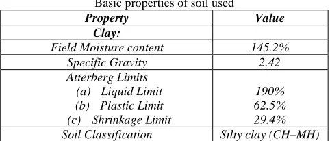
In the model study, a layered soil profile consisting of two alternate layers of clay and sand are used. Clayey soil used in the study was taken from Thayankari area of Kuttanad, Kerala. It was taken from a depth of 4m below ground level. Sandy soil was obtained from River Manimala, Kerala. All the basic tests were conducted based on IS specifications for clay and sand to determine its properties. The soil sample was air dried before using them for laboratory tests. The properties obtained are listed in Table - 1.
Table – 1
Basic properties of soil used
Property Value
Clay:
Field Moisture content 145.2% Specific Gravity 2.42 Atterberg Limits
(a) Liquid Limit (b) Plastic Limit (c) Shrinkage Limit
Cohesion 20kN/m2 Angle of internal friction 30
Sand:
Specific Gravity 2.64 Density of soil in loosest condition, δmin 13.80kNg/m3 Density of soil in densest condition, δmax 16.70kNg/m3 Field Density chosen 15.31kNg/m3 Relative Density 52.40% Angle of internal friction 310 III. EXPERIMENTAL WORK AND METHODOLOGY
Physical modeling is conducted in order to study some particular features in the behavior of prototypes. In this thesis work, modeling is done based on scaling techniques for geotechnical modeling by David Muir. Scaled CPRF model is made using mild steel plate and rods. Experiment is to be done in square tank of dimensions 0.6mx0.6mx0.55m. The variables in present study are number of piles, Spacing of pile and L/d ratio of pile. A loading frame of 2kN capacity is made using channel section. The load is applied by rotating a shaft in clockwise direction. A calibrated proving ring of 2kN capacity is attached to the shaft. Vertical settlement of the piled raft model is measured using 2 dial gauges of sensitivity 0.01mm placed at opposite corners of the raft. The raft slab is modeled using 16mm thick MS plates of size 150mmx150mm. Pile is modeled using 10mm diameter MS bars. The various arrangements of piled raft used are shown in Fig.1.
Fig. 1: Various arrangements of piled raft (a) Plain raft (b) Raft + 1 Pile (c) Raft + 4 Pile (d) Raft +9 Pile (e) Raft + 16 Pile
Three lengths of pile are used in modeling namely 15cm, 20cm and 25cm.The least spacing adopted in this study is 3.75D, where‘d’ is the diameter of the pile. Since the spacing is greater than 2D, group effect of pile is avoided.
The layered soil profile consists of 0.03m clay; 0.03m sand; 0.06m clay and 0.37m sand from top to bottom. A sand bed was formed in the soil bin in layers of 150 mm thickness. To ensure the homogeneity of the sand formation, a designed weight of sand, with an accuracy of 0.001kg, was formed into a certain volume of the soil bin by compaction to give the specified relative density of 52.40%. The different layers of soil are separated by filter paper in order to avoid the mixing of different layers. Before conducting each test, the soil in the tank is to be refilled at the predetermined density. The formed soil was leveled using sharpened straight steel plate and the model piles were then placed on the surface of the compacted soil using driving technique. No inclination in piles or raft is allowed. Table - 2 shows the testing program for the current research.
Table – 2 Testing Programme
Group Test no: No: of piles Outer pile length(mm) Inner pile length(mm)
Plain Raft 1 0 0 0
Raft + 1 pile 2 1 0 150
3 1 0 200
4 1 0 250
Raft + 4 pile 5 4 150 0
6 4 200 0
7 4 250 0
Raft + 9 pile 8 9 150 150
9 9 200 200
10 9 250 250
Raft + 16 pile 11 16 150 150
12 16 200 200
13 16 250 250
5 min for three consecutive readings under the same load or till 1 hour whichever is earlier. Load–displacement relationship for each experiment is plotted.For the loading tests of piled raft in contact with soil, the load is referred as piled raft load, PR.When the raft is loaded without piles, the load is referred as raft load, R. The best configuration of piles in a piled raft for acting as settlement reducer is found using settlement ratio, SR. It is defined as the ratio of average settlements of piled raft and unpiled raft, respectively, at the load, P. Load P corresponds to 15mm settlement in a plain raft case.
Settlement Ratio,SR = wpr/wr (1)
Where wpr and wr are the average settlements of piled raft and unpiled raft, respectively, at the load, P.
IV. RESULTS AND DISCUSSIONS
The Load vs. Settlement graphs plotted as a result of experimental model study for three different pile lengths are shown below:
Fig. 2: Load vs. Settlement graph for pile length = 25cm Fig. 3. Load vs. Settlement graph for pile length = 20cm
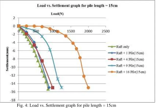
Fig. 4: Load vs. Settlement graph for pile length = 15cm
Based on the data obtained from experiment, settlement ratios are calculated for each case. These are listed in Table – 3. Table – 3
Variation of Settlement Ratio, SR
Pile Raft configuration Length of pile(cm) Settlement Ratio, SR
Raft + 1 pile 15 0.929
20 0.926
25 0.770
Raft + 4 pile 15 0.876
20 0.675
25 0.663
20 0.317
25 0.174
Raft + 16 pile 15 0.032
20 0.095
25 0
From Table – 3, it is clear that when the number of piles increases, the settlement ratio decreases gradually and finally becomes zero when the number of piles is increased to 16. The pile spacing corresponding to 16 pile configuration is 3.75D, where ‘D’ is the diameter of the pile. Hence it can be concluded that decreasing the spacing beyond 3.75D is not necessary for decreasing settlement in a layered soil profile. Every case of a piled raft depends upon the type of soil involved. Hence a general conclusion for all type of soil cannot be made. When the L/D ratio increases from 15 to 25, Settlement Ratio, SR decreases largely and finally becomes zero for Raft + 16 Pile configuration of length 25cm.
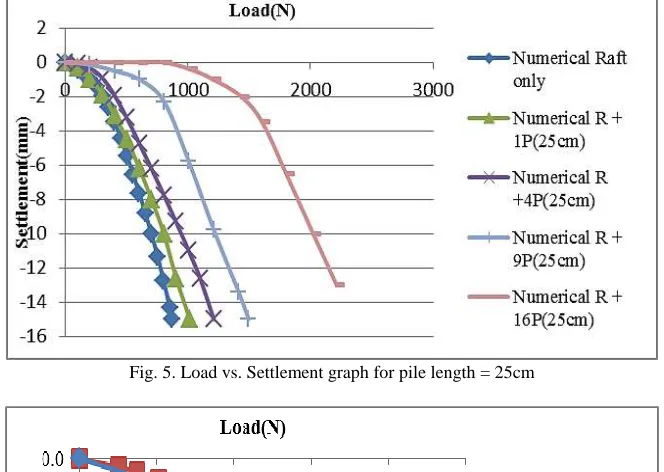
V. VALIDATION OF RESULTS BY NUMERICAL MODELING IN PLAXIS 3D
The results obtained from experimental model study are validated by comparing the results with those obtained from numerical modeling in Plaxis 3D software.
Fig. 5. Load vs. Settlement graph for pile length = 25cm
Fig. 6: Comparison of Load vs. Settlement graph for Raft + 1 Pile (15cm)
VI. CONCLUSION
Based on the conducted model tests, following conclusions have been obtained:
Comparing the load-settlement response of plain raft and piled raft, it is seen that at any given settlement the load taken by the piled raft is greater than that of plain raft.
When the number of piles increases, the settlement ratio decreases gradually from 0.929 and becomes 0.032 when the number of piles is increased from 1 to 16, for L/D of 15cm.
When the L/D ratio increases from 15 to 25, Settlement Ratio, SR decreases gradually and becomes zero for R + 16P configuration of length 25cm.
It can be concluded that as the spacing between piles beyond a value of 3.75D has no effect in reducing settlement. Maximum percentage reduction in settlement occurs at this spacing.
This study focused on study of settlement characteristics of combined pile-raft foundation with various arrangements of pile groups using experimental and numerical models. The work can be extended as follows:
This study can be extended by the application of lateral loads instead of axial loads.
In this study ‘Static Loading’ was given. Instead of that ‘Dynamic Loading’ can be given and its effects can be studied.
The study can be extended by using ‘Bulb Piles’ instead of Circular piles.
REFERENCES
[1] Poulos, H.G. (2001a), “Piled Raft Foundations: Design and Applications”, Geotechnique Vol. 51, No. 2, pp. 95-113
[2] Poulos, H.G. (2001b), “Methods of Analysis of Piled Raft Foundations. A Report Prepared on Behalf of Technical Committee TC18 on Piled Foundations”,
International Society of Soil Mechanics and Geotechnical Engineering.
[3] S.P.Bajad & R. B. Sahu, “An Experimental Study on the Behaviour of Vertically Loaded Piled Raft on Soft Clay”, The 12th International Conference of
International Association for Computer Methods and Advances in Geomechanics (IACMAG) ,1-6 October, 2008, Goa, India
[4] Jaymin D Patil, Sandeep A Vasanwala, Chandresh H Solanki(2014), “An Experimental Investigation On Behavior Of Piled Raft Foundation”, International
Journal of Geomatics and Geosciences, Volume 5, No 2