ISSN (Online): 2320-9364, ISSN (Print): 2320-9356
www.ijres.org Volume 4 Issue 10 ǁ October. 2016 ǁ PP.38-45
www.ijres.org 38 | Page
Engineering Machine Dryer Method of Vacuum with Controlled
Temperature and Pressure
Sakti M.diah
1,A MIdham
2, MuhsinZ
3, Soetyono Iskandar
4.
Abstract:
The purpose of this research is to design and create amodel ofa dryerenvironmentunder 1atmosphereof airpressureanddetermine the performance of the model engine vacuum dryer. Dryingis awaytoreduce thewater content wherecontained in thematerialfromits original stateuntilthedesired finalmoisture content. Vacuum dryingis adryingmethodthat is still rarelyused, dryingmethodhas afortetobe able toshortenthe drying timeandusinga low temperatureascompared toconventionaldryingismuch in use. In this studythe modelhas successfullycreateda vacuumdryer. The performance of this machine can dry the material under the pressure of 1 atmosphere with conditions of pressure and temperature can be in controlKeywords:
dryer, vacuum, design, manufacture, controlI.
INTRODUCTION
Antecedent,
Draining is a heat transfer process and water mass in transient and some process speeds, like physical transformation or chemistry which can cause change quality of result and also mechanism of heat transfer and mass (Mujumdar, 2000). Draining mechanism covers two transfer processes that is heat transfer and transfer of aqueous vapour mass with condition of dryer air.
Vacuum draining happened when evacuation of aqueous vapour from a material takes place at low pressure, is reducing water boiling point and temperature difference between heater medias and bigger material. This thing yields higher draining speed and usage of temperature is more efficient. Sagar and Kumar (2010) and Jaya and Das (2003) reports that at vacuum draining, evaporation of water at food takes place is hard pressed lowness and in a state of very few oxygen or not exist. This shown to oxydative reaction in the form of chocolate colour seldom happened at end product.
Advantage from drainage of vacuum is reducing water boiling point in partial vacuum pressure, what causes vaporization of water at temperature below(under 100°C, and at floor close to high drainage temperature (Bousquet 2000, cited by Yamsaengsung 2008). Amellal and Benamara (2008) date drainage (Phoenix dactylifera L.) lessens water content from around 14% becomes 6,5% at condition of partial pressure 20 kPa at temperature 60oC, 80oC and 100°C. There is no discoloration at reconnaissance, Glorious and Das (2003) where there is no reaction of oxidation is found by below vacuum pressure drainage.
Applies carrot as component of sensitive to temperature by comparing drainage of low dividing valve with heater superheated steam and vacuum drainage. Some parameters quality of from product result of drainage of like volume, contraction, solidity, colour, and vaporization of water is evaluated. Concluded that using superheated low hard pressed steam, quality of higher product from vacuum drainage. Reduces dividing valve at drainage process is one of approach to maintain quality of product (Devahastin et al. 2004)
Heating with microwave is combined with vacuum pressure (Seyfarth dkk 2003, Leiker et al 2004,. Leiker 2007) enables some excellences compared to conventional drainage: decrement of time signifikan (at level of calcium drainage. 7% /minute for accentual beech 40 mbar), there is no discoloration, there is no formation of retak,tidak happened deformation, finite dissociation energy of diatomic efficiency of 80%.
Vacuum pressurizing at drier space will boost up vapour pressure difference on the surface of material with the area so that vapor earth move speed also will increase. Thereby vacuum pressure can increase drainage speed (Bazyma et.al.,2006; Jena and Das,2006; Montgometry etal., 1998).
Some factors influencing inter alia drainage; temperature and humidity of drier atmosphere flown, drier air current debit, initial water content of material, form, scale and battery linear circuit material, form curve sorbsi-desorbsi material, and treatment and way of drainage continuously or existence of tempering (postponement between drainage time taken place), (Anonim,1994) purpose of research is:
1. Design and makes vacuum drainage engine model.
www.ijres.org 39 | Page
II.
MATERIAL AND RESEARCH METHOD
Material applied in making of vacuum drier model covers: Scale steel plate 60 cm x 120 cm, Diameter steel plate 40 cm, Scale spelter plate 20 cm x 50 cm, Acrylics scale 40 cm x 50 cm and Thick 5 mm, Scale glass 25 cm x 30 cm, Tubing can depress, Electrode.
Other device which in using covers: Welding machine, Roll plate, Hand boring, Grindstone, Hybrid recorder Yokogawa 3181, Vacuum pressure gauge, Temperature meter, Noble metal couple type E.
Design and Making of Drainage Model of Material Vacuum. Identification of Problem
Drainage of vacuum needed in knows treatment influence of temperature and accentual to drainage time and quality of material which in drying.
Vacuum drying machine can arrange temperature and dividing valve to yield drainage of maximum grade material
Vacuum drying machine in expecting is quicker processed drainage to get water content which in wishing Drainage engine model of this vacuum needs in developing furthermore for in making reference in planning
of drainage engine design of material vacuum especially home industry scale.
Design Analysis
Design analysis applied to determine requirement of components applied to make drainage model of material vacuum. This analysis consisted of structural functional analysis and analysis equiped with by engineering analysis. In functional analysis done determination of components needed to makes drainage model of laboratory scale vacuum. While analysing structural determines form and components matching with level of requirement of material applied.
Functional design analysis
This engine functions to reduce water content reachs water content which in wishs with treatment of temperature combination trap and accentual so that time processed quicker drainage and can yield quality of better material.
This engine applies element of electrical heater which hot distribution applies blower that heat transfer to equiamplitude surface of quicker material.
Drainage process of material yields vaporization of water where saturated has vapor in drainage process drier space will be desisted causing requires water vapor trap (cold trap).
To know temperature and accentual at drainage process in requiring temperature grader and pressure.
To get temperature which in desired hence drainage engine model of material vacuum in equiping heater earning in controling
To get vacuum pressure which in desired hence drainage engine model of material vacuum in equiping vacuum pump earning in controling
Structural design analysis
Drier room is in the form of platen that usage of flimsier plate material, drier room scale dimension is having diameter 40 cm and long 65 cm
Drier space capable to work for dividing valve 65 Protactiniums
Door of drier space from glass material to can watch drainage process and airtight
Blower for heattransfer from electrical heater to material equiamplitude surface
Cold trap (water vapor trap) made from pipe which in it is flown water by using water pump.
Heater (Heater) drier space temperature mengunakan element of electrical heater for heating of low temperature < 100oC
Range temperature applied in this research is 45-75oC, and during gauging needs also is measured humidity in drier space.
Dividing valve required during drainage process to reach 34 cmHg, so that to obtain the condition is applied by rotary vacuum pump.
Vacuum drier Performance Testing
www.ijres.org 40 | Page
pressure at drier space consisted of accentual 3 that is 36 cmHG, 56 cmHg. For distribution of temperature in drier space, applies blower and air current director from heater,gauging of distribution of temperature applies 7 noble metal couple (figure1), placement of noble metal couple each distance 25 cm in strarting from basis.Figure 1. Placement of noble metal couple for distribution of hot temperature in space Drier
III.
RESULT AND SOLUTION
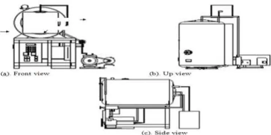
Vacuum drier made for drier process performance covers pressure, temperature and drainage time overall of drying machine is consisted: drier space, heater system, temperature vapor trap (cold trap), piping system, water tank, vacuum pump and control panel. arrangement of This engine in addressingat figure 2 and 3.
Figure 2. Arrangement of Vacuum drying machine model
At vacuum system, atmosphere in pump from drier space through tubing can depress to vacuum pump and through tubing can depress to water receiver space result of vapor from cold trap in drier space to vacuum pump. Cold this trap applied to catch the vapor in atmosphere to avoid saturation of vapor in drier space causing drainage process of material can take place and only dry steam coming into pump vacuum system cold this trap in the form of copper pipe which in it is flown water from cool water tank which circulation during drainage process by using water pump dyes
Figure 3. Vacuum drier equipments scheme
Drier Space
Drier space applied in design to apply thin plate so that is in the form of platen. Before drier space used, formerly is done calculation steel plate Thick matching with performance of vacuum power.
Emphasis at drier space wall happened because difference between pressure in pv drier space and outside drier
space patm. Because pressure in very small drier space (vacuum) while dividing valve outside space is
atmospheric pressure hence happened encumbering of compress in to figure. termo
kopel
he
ate
r
bl
ow
er
Dindin g ruang pengeri ng Cold
trap
Co ld tra p
M H
e at e r
www.ijres.org 41 | Page
At this scheme applied drier space made from carbon steel. Strain yiel material σy steel is 340 Mpa andsecurity and safety factor of nitrogen applied 1.67 (Gere et al1987). With strength data of this material, can be searched allowance strain σi.
𝜎𝑖 = 𝜎𝑦
𝑛 = 203.6𝑀𝑃𝑎 ………(1)
If vacuum pressurepv=10cmHgatau13.3Kpa and atmosphere pressure patm = 101.3 kpa, hence drier space wall
pressureΔp = patm + pv =114.625kpa
Figure1.Emphasis payload at drier space wall
Drier space diameter applied 04 m and long 06 m, hence can be searched the wall Thick by considering some kinds of encumberings.
Radial burden
𝜎𝑖 = 𝐹𝑡
𝐴= ∆𝑝𝜋𝑑𝑙
2𝑥𝑑𝑝𝑙……….………..………(2)
hence,
𝑥𝑑𝑝 = ∆𝑝𝜋𝑑
2𝜎𝑖 = 0,35𝑚𝑚………..………..……….(3)
Axial burden
𝜎𝑖 = 𝐹𝑡
𝐴= ∆𝑝𝜋4𝑑2
𝜋𝑥𝑑𝑝𝑑……….…………...…..……(4)
𝑥𝑑𝑝 = 0.25∆𝑝𝑑
𝜎𝑖 = 0.06 𝑚𝑚………...…..……...(5)
From result of calculation with encumbering of radial in earning drier space wall plate Thick which in requires 0,35 mm, while with encumbering of axial thick which in requires 0044 mm, because plate thick which in using bigger (2 mm) from Thick result of calculation encumbering, hence strong drier space plate for in encumbering.
Door Of Drier Space
Door of drier made of glass. Value σult glass is known is 10 x 10 8
Pa. Garmo (1984) tells that if strain applied is σult, hence security and safety factor which must be applied is 2.8. with this data hence can be
searched σi (Gere et al. 1987) 𝜎𝑖 =
𝜎𝑢𝑙𝑡
𝑛 = 3.57 𝑥10
8𝑃𝑎………..(6)
Thickness of door of determined by using equation of continuity of 4 by changing variable xdp to become spp. 𝑥𝑝𝑝 =
0.25∆𝑝𝑑
𝜎𝑖 = 3.21 𝑥10
4 ………...(7)
Because result of calculation strength of material shows glass door thick required is 0.321 mm while glass thick which is made 10 mm, hence inferential door of up to standard drier of material strength.
Vacuum pressure
Vacuum pump applied is pump rotari model 2X, 2 phase, with electricity 0.18 kW. This pump can flow atmosphere with speed of 05 liter/second and yields 0.07 Pa. To flow low pressure atmosphere is applied by pipe flexibel is having diameter ½ inchi.
Dimension Pipe Cold Trap
Derivation of vapor temperature in drier space is done by flowing water in pipe paired with water pump to dye. Dimension pipe and pipe material is determined by considering transformation of vapor becomes water at pipe wall. Dimension pipe which in selecting ½ inchi from copper material having conductifity which either in comparing other metals
Heater
Drainage temperature applied in this research is less than 100oC. by considering drier space volume causing is applied 1 fruit of heater and long 50 cm with power 500 W.
Temperature control and pressure
www.ijres.org 42 | Page
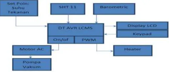
Microcontroller applied is DT AVR Low Cost Micro System with programming capacity of memory equal to 8 kb.Figure 2.System scheme controller of vacuum drying machine model.
Microcontroller which in the form of DT-AVR Low Cost Micro System receives input setpoint temperature and pressure, hereinafter every one seconds read data of temperature from SHT 11 and accentual from Barometric will be compared to set point given.
Figure3.Vacuum drier equipments
Vacuum drier Performance
Pressure drop at initial minutes can take place faster because pumping of atmosphere from drier space into the air free easier to be caused pressure difference in and external has not too big. When drier space dividing valve has reached dividing valve 0.38 cmHg to setpoint vacuum pump work to desist.
Vacuum pump will work if such dividing valve had reached 0.38 cmHg below setpoint. At pressure setpoint 64 cmHg worked repeatable vacuum pump around 2 minutes and time vacuum of 4 seconds to reach 0.38 cmHg to setpoint 64 cmHg. At dividing valve setpoint 49 cmHg worked repeatable vacuum pump around 15 minutes and time vacuum of 10 seconds to reach 0.38 cmHg to setpoint 49 cmHg. At dividing valve setpoint 34 cmHg worked repeatable vacuum pump around 1 minute and timevacuum of 3 minute to reach 0.38 cmHg to setpoint 64 cmHg.
Figure 4.Pressure drop to time 25
45 65
0 3 5 8 10 13 15 18 20 23 25
tek
a
na
n (
cm
H
g
)
waktu (menit)
www.ijres.org 43 | Page
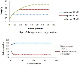
At temperature setpoint is controling, temperature read lower than setpoint hence microcontroller will give pwm (pulse width modulation) appropriate to reach setpoint given and if setpoint temperature had been reached hence will be given pwm appropriate to maintain temperature as according to setpoint. Heating time heater until reaching setpoint 45oC during 7 minutes for setpoint 60oC during 18 minutes while at setpoint 75oC requires time 40 minutes. Transformation of temperature after reaching setpoint ± 1oCFigure5.Temperature change to time.
Figure6.Pressure transformation and temperature to time
Figure 7.Transformation of Humidity of atmosphere in drier space
www.ijres.org 44 | Page
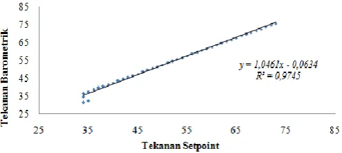
Pressure Validation Setpoint.Result from control setpoint drainage vacuum pressure at drier space in validation by means of
barometric instrument which has been attached in wall outside drier space with result at figure 12 hereunder and coefficient of determination value (R2) what yielded comes near 1, mean result of pressure control comes near result of gauging barometric.
Figure9. Pressure Validation Setpoint
Temperature Validasi Setpoint
Result from control setpoint drainage temperature at drier space in validation by means ofnoble metal couple instrument attributed to by hybrid recorder with result at figure 13 hereunder and coefficient of determination value (R2) what yielded comes near 1, mean result of temperature control comes near result of noble metal couple gauging.
Figure 10.TemperaturValidasi Setpoint
IV.
CONCLUSION AND SUGGESTION
1. At this research has successfully is made vacuum method drying machine.
2. This engine performance can dry material under pressure 1 atm with condition of pressure and temperature earning in controling.
Suggestion
1. At this drying machine need to be given hot insulation at drier space wall so that hot from heater earns in optimal for heating of material only.
2.The importance of measuring instrument of material water content earning in placing in drier spaces.
REFERENCES
[1]. Adam Figiel.2010. Drying kinetics and quality of beetroots dehydrated by combination of convective and vacuum-microwave methods. Journal of Food Engineering 98 : 461–470
[2]. Apichart Artnaseaw, Somnuk Theerakulpisut, Chatchai Benjapiyaporn. 2010. Development of a vacuum heat pump dryer for drying chilli, bio systems engineering 105 : 130 – 138.
[3]. Arun S. Mujumdar. 2006. Handbook of Industrial Drying . third edition, Taylor & Francis Group. [4]. Bousquet, D. 2000. Lumber Drying: An overview of current processes; Extension of Forest Resources
Specialist, University of Vermont, Extension and School of Natural Resources.
[5]. B. Zecchi⇑, L. Clavijo, J. MartínezGarreiro, P. Gerla.2011.Modeling and minimizing process time of combined convective and vacuum
www.ijres.org 45 | Page
[7]. Devahastin, S. P. Suvarnakuta, S. Soponronnarit and A. S. Mujumdar. 2004. A Comparative Study Of
Low-Pressure Superheated Steam And Vacuum Drying Of A Heatsensitive Material. Drying Technology 22(8): 1845 – 1867
[8]. Hee-Suk Jung,Chang-Deuk Eom, and Bum-Joon So, 2004, Comparison of Vacuum Drying Characteristics of Radiata Pine Timber Using Different Heating Methods,Drying Technology, Vol. 22, No. 5, pp. 1005–1022
[9]. He-Sheng Ren,Construction of a generalized psychrometricchart for different pressures, International Journal of Mechanical Engineering Education 32/3
[10]. Inci T€urk To_grul , Dursun Pehlivan.2003. Modelling of drying kinetics of single apricot. Journal of Food Engineering 58 : 23–32
[11]. Jaya, S. and H. Das. 2003. A vacuum drying model for mango pulp. Drying Technology 21(7): 1215 – 1234.
[12]. Joseph Edward Shigley,Larry D. Mitchell. PerencanaanTeknikMesin. Ed-4. Jakarta: Erlangga.1999 [13]. K. W. Ragland, D. J. Aerts. 1991. Properties of Wood for Combustion Analysis. Bioresource
Technology 37 : 161-168
[14]. Lazarescu, Ciprian, Avramidis, Stavros . Oliveira, Luiz. 2009. 'Modeling Shrinkage Response to Tensile Stresses in Wood Drying: I. Shrinkage-Moisture Interaction in Stress-Free Specimens',Drying Technology,27:11,1183 -1191
[15]. Leiker, M., Adamska, M.A., Guttel, R., Mollekopf, N.2004: Vacuum Microwave Drying of Beech: PropertyProfiles and Energy Efficiency. Proceedings COST E15 Conference, Athens-Greece
[16]. Liu, Jen Y. And Simpson, William T.(1999)'Two-Stage Moisture Diffusion In Wood With Constant Transport Coefficients',Drying Technology,17;1 :258 – 267
[17]. Long Wu, Takahiro Orikasa, Yukiharu Ogawa, Akio Tagawa.2007. Vacuum drying characteristics of eggplants. Journal of Food Engineering 83 : 422–429
[18]. Long Wu, Takahiro Orikasa, Yukiharu Ogawa, Akio Tagawa.2007. Vacuum drying characteristics of eggplants. Journal of Food Engineering 83 : 422–429
[19]. Lyes Bennamoun *, Azeddine Belhamri. 2003.Design and simulation of a solar dryer for agriculture products. Journal of Food Engineering 59 : 259–266.
[20]. Noji, K., Masaoka, H., Kanagawa, Y. 2001: Wood Drying with High Temperature Heating by Radio- Frequency under Vacuum after Treating of Local Steam Explosion. Proceedings of 7th International IUFRO Wood Drying Conference, Tsukuba-Japan: 134-139
[21]. Nils Grothe, Nasko Terziev, Ulrika Raberg, 2010,Drying of Wood in Oil Under Vacuum. Didalam : Tom Morén, Lena Antti ,Margot,IUFRO,recentandvancein the field of wood drying, Proceedings of the 11th International IUFRO Wood Drying Conference Recent Advances in the Field of Wood Drying, January 18-22
[22]. Resch, H., Hansmann, C. 2002: Tests to Dry Thick Eucalyptus Boards in Vacuum Using High-Frequency Heating. Holzforschung und Holzverwertung 54(3): 59- 61.
[23]. Resch, H. 2003: High-Frequency Heating Combined with Vacuum Drying of Wood. Keynote Address.Proceedings of 8th Int. IUFRO Wood Drying Conference, Brasov-Romania.
[24]. R. Seyfarth,M. Leiker,N. Mollekopf.2003.Continuous Drying of Lumber in a Microwave Vacuum Kiln.8thInternational IUFRO Wood Drying Conference.
[25]. Sagar, V. R. and P. S. Kumar. 2010. Recent advances in drying and dehydration of fruits and vegetables: a review. Journal of Food Science and Technology 47(1): 15 – 26
[26]. S. Jaya , H. Das, . 2003 A Vacuum Drying Model for Mango Pulp, Drying Technology,Vol. 21, No. 7, Pp. 1215–1234
[27]. Seyfarth, R., Leiker, M., Mollekopf, N. 2003: Continuous Drying of Lumber in a Microwave Vacuum Kiln. Proceedings of 8th Int. IUFRO Wood Drying Conference, Brasov-Romania.
[28]. ThitinanSattho, Ram Yamsaengsung.2005. Vacuum Drying Of Rubberwood.Psu-Uns International Conference On Engineering AndEnvironment - Icee-2005, Novi Sad 19-21 May
[29]. Yamsaengsung, R and T. Sattho. 2008. Superheated steam vacuum drying of rubberwood. Drying Technology 26: 798 – 805
[30]. Wibawa endra juwana,2007,koofesien difusi pada pengeringan bahan mahoni di sekitar kandungan air kritik,gema teknik nomor 1
[31]. Zahrial Coto,2005,Penurunan Kadar Air Keseimbangan dan Peningkatan Stabilitas Dimensi Bahan dengan Pemanasan dan Pengekangan, J. Ilmu & Teknologi Bahan Tropis Vol. 3 • No. 1 •